Step 1: Beginning an SDS2 Job
- What is a Job/Project?
- What is a Fabricator?
- What is the Master Fabricator?
- What are Job Settings?
- What is my current Job, Fabricator and Repository?
- Changing your Job
- Changing your Fabricator or creating a new one.
- Resolve Missing Materials
Also see:
- Job Repositories (sets directories for Jobs)
- Project Transfer (compacts or unpacks a Job and Fabricator for transfer)
- Job/fab selection method (what happens at startup)
- Copy Project Items (to copy items into your current Job)
- Copy Job (alternative way to create a new Job)
- Delete Jobs (to delete Jobs you have created)
- Event Logging (Job creation is logged when the job Operations box is checked)
- Log Viewer (A job creation log entry is displayed when the job Operations box is checked)
- A Project is another name for a Job.
- A Job is a file folder (
 ) maintained in a Job repository that stores information about all members that you lay out when you build a structure (a 3D model) in SDS2. The Job also contains all drawings that are maintained in the Drawing Editor.
- When you Change your current Job, you change to a different 3D model, and the Master Fabricator contained in that new Job automatically becomes your current Fabricator.
- Job Settings is a part of Home > Project Settings and is stored in your current Job. If you send a Job folder ( ) to another user, that folder will include the Job Settings file and all Fabricators that are stored in that Job.
What is a Fabricator?
What is the Master Fabricator?
What are Job Settings?
What is my current Job, Fabricator and Repository?
A Job and a Project are the same thing. The current Job (Project) and Fabricator are listed in the upper, left corner of Home. Also at this location is the Job repository (file folder) where your current Job (Project) is stored.
|
|
"jobname" = current Job (Project).
"fabname" = your current Fabricator. "reponame" = Job repository in which "jobname" is stored. |
You can change the Job by clicking its "jobname". When you change the Job, that Job becomes your current Job. The Master Fabricator that is in the selected Job automatically becomes your current Fabricator.
The
The
The
Report Writer: CurrentLocationJob
Report Writer: CurrentLocation.Fabricator
Changing your Job (Project) or creating a new one:
The following procedure describes how to switch to a different Job (step 2, alternative 1) and how to create a new Job (step 2, alternative 3 & step 3). After completing this procedure, a different Job will become your current Job, and the Master Fabricator that is contained in that Job will become your current Fabricator.
1. On the upper, left corner of Home, press the jobname button.
|
|
Click jobname to change your current Job |
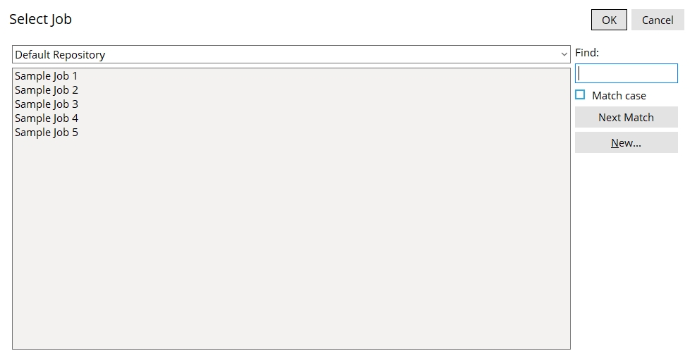
2. The Select Job screen appears on the Home window. On it is a list of all Jobs that are in the file folder (directory) in which your current Job is located. Note that you can change to a different Job repository (directory) and so get a different list of Jobs. Do one of the following:
Option 1: If the Job you want is on the list, double-click its name (or select its name and press OK).
Option 2: If your current Job is the one you want, press the Cancel button to end this operation.
Option 3: To create a new Job to be your current Job, press the New... button and go to step 3.
3. If you pressed New..., the Create New Job screen appears.
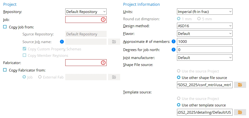
------ Project ------
Repository: The folder (repository) in which the Job you are creating will be stored. You can add new repositories using the Utility Functions option Job Repositories.
Job: The name (up to 64 characters) that you want to give the new project you are creating. Job file names can be made up of letters and/or numbers with "_" or "." used as optional separators.
If this box is checked (
), then you can select a Repository and select a Source Job name. Job items such as sheet outlines, user defined connections, Fabricator Setup data and Job setup data will be copied FROM the Source Job name TO the new Job you are creating. You can also, optionally, Copy custom property schemas.
If the box is not checked (
), a default Job setup file is created for you, and the new Job you are creating will not have any previously created user defined connections. You will still have options to copy a Fabricator (to be the master fabricator), templates and a shape file from other Jobs.
Source repository: The folder (repository) from which you want to select the Source Job name below. This applies when
is checked. Source Job name: This applies when
( and double-click the Job name that you want that is on the list.)
Copy Custom Property Schemas:
If this box is checked (
If the box is not checked (
Copy Member Revisions:
If this box is checked (
If the box is not checked (
Fabricator: The file name (up to 64 characters) you want to give the new Fabricator. A Fabricator file name can be made up of letters and/or numbers with "_" or "." used as optional separators. The Fabricator will be stored in the new Job you are creating and will be the Master Fabricator for that Job.
Copy Fabricator from:
If this box is checked (
Job or
If the box is not checked (
------ Project Information ------
Design method: ASD 16 or ASD 15 or ASD 14 or ASD 13 or ASD 9 or LRFD 16 or LRFD 15 or LRFD 14 or LRFD 13 or LRFD 3 or CISC 12 or CISC 11 or CISC 10 or CISC 9 or CISC 8 or EUROCODE 3 or EUROCODE 3 UK or CHINA GB50017-2003 or INDIA IS800-2007. The selection made here affects the design phase of Process and Create Solids. The option is disabled when you specify a Source Job name since that source Job will set the connection design method. Click here for more detailed information. Changing the Design method may also change the Shape file source. Design method is disabled (grayed out) when you have elected to Copy custom property schemas from the Source Job name.
Method Design Specifications ASD 16 AISC Steel Construction Manual,
Sixteenth EditionASD 15 AISC Steel Construction Manual,
Fifteenth EditionASD 14 AISC Steel Construction Manual,
Fourteenth EditionASD 13 AISC Steel Construction Manual,
Thirteenth EditionASD 9 AISC Manual of Steel Construction, Allowable Stress Design, 9th Edition LRFD 16 AISC Steel Construction Manual,
Sixteenth EditionLRFD 15 AISC Steel Construction Manual,
Fifteenth EditionLRFD 14 AISC Steel Construction Manual,
Fourteenth EditionLRFD 13 AISC Steel Construction Manual,
Thirteenth EditionLRFD 3 Manual of Steel Construction, Load and Resistance Factor Design, 3rd Edition CISC 12 CISC Handbook of Steel Construction,
Twelfth EditionCISC 11 CISC Handbook of Steel Construction,
Eleventh EditionCISC 10 CISC Handbook of Steel Construction,
Tenth EditionCISC 9 CISC Handbook of Steel Construction,
Ninth EditionCISC 8 CISC Handbook of Steel Construction,
Eighth EditionAS 4100 Standard for Steel Structures, AS4100 -- 1998 Eurocode 3 Eurocode 3: Design of steel structures Eurocode3 UK CHINA GB50017 - 2003 Code of Design of Steel Structures, GB-50017-03 INDIA IS800-2007 Indian Standard, General Construction In Steel -- Code of Practice, Third Edition, IS 800: 2007 Units: Imperial (feet-in frac) or Imperial (inches-sixteenths) or Imperial (inches fraction) or Imperial (inches.decimal) or Metric (mm). This sets the primary dimensioning Units that you want to be used when the Job you are creating uses the Fabricator whose name you entered above.
Units Examples Imperial (ft-in frac) 10-6 1/2 is ten feet, six-and-a-half inches. Imperial (inches-sixteenths) 24-8 is two feet and one-half inch. Imperial
(inches fraction)24 1/2 is two feet and one-half inch. Imperial (inches decimal) 24.5 is two feet and one-half inch. Metric (mm) 1000 is one thousand millimeters or one meter. Also: Imperial weights are in pounds. Imperial loads are in kips. Metric weights are in kilograms. Metric loads are in kilonewtons. Click here for more information. Round cut dimension: 1 mm or 5 mm. This applies when the primary dimension Units are set to Metric. It sets the rounding method that connection design will apply when setting the lengths and widths of shear plates, bent plates, end plates, auto base/cap plates, stiffeners, etc.
1 mm instructs connection design to round plate lengths and widths up to the nearest millimeter. Canadian users of SDS2 may prefer this option.
5 mm instructs connection design to round plates up to the nearest 5 millimeter increment. This is generally the preferred choice for European users of SDS2.
Also see: Round cut dimensions in Design Criteria can be used to reset the choice made here. Home > Project Settings > Fabricator > Standard Fabricator Connections > Preferred Connection Material Sizes > Preferred Plate Sizes lets you set the thickness of the various plates whose lengths and widths are affected by the choice made here.
Flavor: Default or None or CollaborativeProperties or DDLegacy or ElectronicApporval or Modular or Other flavors may be listed on this list box's menu
( . A flavor is a set of custom properties. The set of custom properties that is selected here is copied into the new Job (Project) you are creating, where the individual schema that make up that flavor can be edited, deleted or added to using setup options for member schema, material schema, etc. Flavor is disabled (grayed out) when you have elected to Copy custom property schemas from the Source Job name.)
| Modular Flavors (provide user-friendly management with Activate Custom Properties) (can be updated or added to using setup options) (put custom property settings on the Edit Properties window) |
|
| Selection | Effect on the New Project |
| Default |
functionality is the same as or similar to Modular. |
| Modular |
provides preconfigured sets of custom properties that you can add using Home > Project Settings > Job > Custom Properties > Activate Custom Properties. Generally speaking, the flavor consists of updated versions of properties that were originally developed for the Collaborative Properties and Electronic Approval legacy flavors. The new properties are added without your having to mess with Python scripts. |
| Other flavors |
are listed on this list box's menu ( |
| Legacy Flavors (put custom property settings on the Custom Properties window) (may be phased out in later versions of SDS2 software) |
|
| Selection | Effect on the New Project |
| Collaborative Properties |
gives you the same capabilities and compatibilities as ElectronicApproval, but adds additional predefined properties for intercommunications with the connection engineer. |
| DDLegacy | is a set of custom properties that was originally developed for v7.2, v7.3 and v2015 versions of SDS2 software. |
| Electronic
Approval |
is a set of custom property schema which can be used for electronic approval of the 3D model and drawings. |
| Other flavors |
are listed on this list box's menu ( |
| None | results in no preset legacy custom properties being available in this new Job you are creating. You can still add custom properties using setup options for member schema, material schema, etc. |
| CollaborativeProperties and DDLegacy and ElectronicApproval incorporate Python dialogs as the user interface for Custom Properties as described here or here. |
Approximate # of members: A count (up to 150,000) that represents the estimated number of members you expect to have in the new Job you are creating, plus an extra 10% to 30% to make room for revisions and deleted members. Space on the hard drive is allocated according to the estimate you make here. If necessary, you can later increase your estimate using the Change File Sizes utility. If the initial estimate that you enter here is sufficiently large, and you actively use the Release Submaterial Marks and Release Deleted Members utilities to keep your Job from growing too large, you should probably never have to use the Change File Sizes utility.
Degrees for job north: A positive or negative angle from 180 to -180 degrees. This sets the entry made to Degrees for job north at Home > Project Settings > Job > Modeling > Job North. Degrees for job north is disabled (grayed out) when you have elected to Copy custom property schemas from the Source Job name.
Degrees for job north sets north in Modeling plan views and on plan view drawings.
Degrees for job north also sets the direction that Face A of a column will be marked to face. Click here for more information about job north.
Joist manufacturer: Default or Canam or Vulcraft or Other joist manufacturers. This sets the Joist manufacturer that is selected in Project Settings. You can change to a different Joist manufacturer at a later time, after the new Job you are creating has actually been created. The Joist manufacturer that is selected in Project Settings limits the joist section sizes that are available to you, on the Joist Edit window in Modeling, to sizes that are associated with that manufacturer.
Joist manufacturer The Shapes Properties section in the local shape file that populates the Section size selection list that opens when you press the Default Joist: Default Canam Joist: Canam Vulcraft Joist: Vulcraft Default is a joist manufacturer much like any of the other choices you have for joist manufacturer. No custom BIM information is provided for this manufacturer, but it does let you create, for example, user configured panels that provide considerable modeling detail. A Joist: Default section will be populated with joist sizes in your local shape file. After your new Job has been created, you can use the Joist Manufacturers Manager utility to add a Joist: Canam or Joist: Vulcraft section.
Canam is a manufacturer plugin that is provided by Canam Group Inc. It supports the import of as-built or as-designed joists and custom BIM shapes and also supports joist export to Canam's design software. Joist: Canam and Joist: Default sections will be populated with joist sizes in your local shape file.
Vulcraft is a manufacturer plugin that is provided by Nucor-Vulcraft. It provides preconfigured panels for specific parallel joists. Joist: Vulcraft and Joist: Default sections will be populated with joist sizes in your local shape file.
Other joist manufacturers may provide plugins compatible with SDS2 software and can be listed here if they have been installed in the data directory used by your current version of this program.
Note: Only one joist manufacturer can be in use at a time for modeling purposes in a project. If you want to create a model that produces BIM information from more than one manufacturer, you can set the Model complete date for those joists that use BIM information from that manufacturer, then change to a different Joist manufacturer at Home > Project Settings > Job > Modeling > Joist Manufacturers.
Shape File source: Use the source Project or Use other shape file source. The choice made here is for copying an existing shape file for use as the local shape file in the new Job you are creating.
Use the source Project specifies that the local shape file used in the source project (Source Job name) will be copied into the new Job you are creating. In that new Job, that shape file will be the local shape file.
Use other shape file source lets you specify a file path to any shape file on your network. The default path is set according to the Design method that you selected (above). To change the default, use the "file" button (
| Examples of shape file paths: | |
| /*/main/job_mtrl | * = file path to a Job. This is the path to the local shape file in that Job. |
| /*/conf_mtrl/SDS2 | * = file path the data directory used by your current version of this program. This folder contains the default USA (usa_mtrl), default Canadian (can_mtrl) and default All (all_mtrl) shape files. These files are updated when SDS2 is updated to a newer version. |
| /*/conf_mtrl/usa_mtrl
/*/conf_mtrl/can_mtrl /*/conf_mtrl/all_mtrl Tip: One of these is usually your best choice. |
* = file path to the data directory used by your current version of this program. These are the USA, Canadian and All shape files. Users may update these files as they please. These files are not overwritten when you update to a newer version of SDS2. |
Template file source: Use the source project or Use other template source.
Tip 1: To get the latest templates from SDS2, select Use other template source and use the "file cabinet" browse button
( to set .../detailing/SDS2 as the desired path.
Tip 2: If, after creating your new Project, you decide that you want to update its templates, you can use the Copy Detailing Templates utility.
Use the source project specifies that templates that are maintained in the fabs folder in the Source Job name be copied into the fabs/default_templates folder in the new Job you are creating.
Use other template source lets you specify a path to a folder that you want to copy templates from. Inside the new Job that is created, you will find copies of these templates in the
Examples of template source file paths: /*/detailing/Default * = file path to a Job. The path to the detailing/Default folder is the default choice for the Template file source. /*/detailing/Default * = file path to the data directory used by your current version of this program. When Use other template source is selected, this is the folder that, by default, the template folders will be copied from. /*/detailing/SDS2 * = file path to the data directory used by your current version of this program. This folder contains the most recently updated template files. */detailing/MyTemplates
or any other pathIf you use the "file cabinet" browse button ( Alternative 1: Press the OK button to create the new Job.
Alternative 2: Press the Cancel button to end the Change Project operation without creating a new Job.
4. Unless the Resolve Missing Materials window or the Access Control Station Error dialog opens in the meantime, you should now be back at Home. Also, if in step 2 you selected a Job (instead of pressing New...) and that Job does not currently have a Fabricator stored in it (e.g., because it is an old Job), you will be prompted to select a Fabricator.
As a result of your taking the above steps: The new Job you selected in step 2 (or created in step 3) will be listed in the upper, left corner of Home. Listed below the Job will be the Master Fabricator. To change to a different Fabricator, see the procedure described below.
Tip 1: At this time you may want to double-check your Job/Fabricator Option files at Home > Project Settings as described in Double Checking Job / Fabricator Settings. It is a good idea to set up these up before you create a 3D model or generate drawings.
Tip 2: If you didn't already specify a Source Job name to copy items from, you may now want to use the Copy Project Items utility to copy standard details, sheet outlines, user defined connections or etc. from other Jobs.
Changing to a different Fabricator, or creating a new Fabricator
Multiple Fabricators can be stored in the ![]() fabs folder used by your current Job. This procedure allows you to add a new Fabricator to that folder (step 2, alternative 3 & step 3) and it also tells you how to switch to a different Fabricator (step 2, alternative 1). Be aware that only the Master Fabricator controls the assigning piecemarks phase of Create Solids as it relates to standard piecemarks. However, there are other automatic processes that Fabricator Setup options control. You might want to change to a different Fabricator in order to control particular aspects of automatic detailing or connection design or various modules. For example, the Detailing Defaults window might be set up so that
fabs folder used by your current Job. This procedure allows you to add a new Fabricator to that folder (step 2, alternative 3 & step 3) and it also tells you how to switch to a different Fabricator (step 2, alternative 1). Be aware that only the Master Fabricator controls the assigning piecemarks phase of Create Solids as it relates to standard piecemarks. However, there are other automatic processes that Fabricator Setup options control. You might want to change to a different Fabricator in order to control particular aspects of automatic detailing or connection design or various modules. For example, the Detailing Defaults window might be set up so that ![]() Detail using templates
Detail using templates
| Note 1: The Master Fabricator in a particular Job is created when you create a new Job. This procedure explains how to create a new, secondary Fabricator. |
| Note 2: When you switch to a different Fabricator, you need to restart Modeling to have that Fabricator be the one that is used in Modeling. |
1. At the upper left corner of Home, click the name of your current Fabricator (e.g., "fabname").
|
|
Click "fabname" in this example to change to a different Fabricator. Note: When you switch to a different Fabricator, you need to restart Modeling to have that Fabricator be the one that is used in Modeling. |
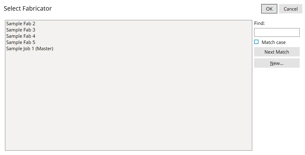
2. The Select Fabricator screen appears on the Home window. On it is a list of the Fabricator files that are stored in your current Job's ![]() fabs folder. Do one (1) of the following:
fabs folder. Do one (1) of the following:
Option 1: To select a different Fabricator, double-click its name (or select its name and press OK).
Option 2: If your current Fabricator is the one you want, press the Cancel button to end this operation.
Option 3: To create a new Fabricator, press the New... button and go to step 3. Access control: You will not have a New button to press if Create new fab is turned off (not checked) for your login name in the Access Control utility.
3. If you pressed New..., the Create New Fabricator screen appears:
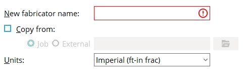
New fabricator name: The file name (up to 64 characters) of the new Fabricator you want to create. Fabricator file names can be made up of letters and/or numbers with "_" or "." used as optional separators.
Copy from:
Units: Imperial (feet-in frac) or Imperial (inches-sixteenths) or Imperial (inches fraction) or Imperial (inches.decimal) or Metric (mm). This sets the primary dimensioning Units that you most commonly use when entering distances and that SDS2 uses when showing distances on drawings or in the 3D model. Note that you will not be restricted to the units you select -- you can also enter other units. This option is disabled when you Copy from another fabricator.
| Units | Examples |
| Imperial (ft-in frac) | 10-6 1/2 is ten feet, six-and-a-half inches. |
| Imperial (inches-sixteenths) | 24-8 is two feet and one-half inch. |
| Imperial
(inches fraction) |
24 1/2 is two feet and one-half inch. |
| Imperial
(inches decimal) |
24.5 is two feet and one-half inch. |
| Metric (mm) | 1000 is one thousand millimeters or one meter. |
| Also: Imperial weights are in pounds. Imperial loads are in kips. Metric weights are in kilograms. Metric loads are in kilonewtons. Click here for more information. | |
Alternative 1: Press the OK button to create the new Fabricator.
Alternative 2: Press Cancel to end this operation without changing your Fabricator.
4. You should now be back at the Home window.
As a result of the above: The Fabricator you selected in step 2 (or created in step 3) will be listed as the current Fabricator in the upper, left corner of Home and at the top, middle of the Setup Job or Fabricator Options window.
Resolve Missing Materials
The Resolve Missing Materials window opens if, after you Change to a different Job or Fabricator, validation detects a material section size in setup that does not exist in the local shape file.
Fabricator Setup: Initially, when you Change the Fabricator, any section sizes that are in the Fabricator but are not in the local shape file are deleted from the Fabricator. However, default section sizes are not removed -- they must instead be resolved using the Resolve Missing Materials window.
Job setup: The only section sizes that are in Job setup are those that have been defined by users to be used for specific User Defined Connections. In your current Job, you define these components by choosing a section size from the local shape file, and that component should subsequently remain available so long as it is not deleted from the local shape file. If, however, you import (Copy Project Items) a user defined connection from another Job, and your current Job's local shape file does not have a section size for a component part of the imported user defined connection, you will find a blank field where that component's section size is specified.
The Resolve Missing Materials window applies to only those section sizes that are populated in setup. Since the section sizes for invalid user defined connections are blank (not populated), they are not resolved using Resolve Missing Materials. Similarly, of those Fabricator section sizes that are not in the local shape file, only those section sizes that are filled in with default sections are populated. The Resolve Missing Materials window only applies to default section sizes.
Also see: The Submaterial Piecemarking Conflict window is another window that may also open to let you resolve conflicts when you Change Project.
Resolution method #1:
1. Press the file button (
2. Write down the section size(s) that you selected, then press OK.
3. Print out a Fabricator Settings Report to the report viewer. Do a search in the report for each section size that you wrote down in the previous step. The search should help you to pinpoint exactly where the section size you replaced is used in setup.
Resolution method #2:
1. Write down the section size(s) that need to be replaced. In the example above, this would be only a single section size, C7x12.25.
2. Use the Copy Shapes utility to copy those section sizes into your local shape file.

