Entering Dates, Distances, etc. (topics)
On this page :
- Text entry widgets
- Entering dates
- Entering distances
- Distance and angle constraints for point location
- Entering angles
Also see :
Text entry widgets ( these apply when a cursor is in an entry field ).
To move from one entry widget to the next on an entry window (from cell to cell on a setup table), use ↑ or ↓ or Tab or Shift + Tab , or roll forward or backward with your mouse wheel .
Typing file names: The length of a file name in SDS2 is typicall y limited to 61 characters. Remember when typing in the name of a file that capital and lower case letters are critical, as is any punctuation within the name. This applies to erection views, job standard details, members, Jobs, Fabricators, submaterials, global standard details, details, sheet outlines, etc. are all given individual file names. Blank spaces are allowed in most file names. You should, however, avoid special characters such as % # ', . [ \ ] { }, etc. Also, for file exchange purposes, you may want to use an _ (underscore) instead of a blank space in the file name. For example, if you do a VRML Export or a VRML Export from the Model , the space character in a member piecemark in the exported file is changed to %20 in order to comply with the VRML standard.
Drag and release selects a group of characters. Typing in any character when a group of characters is selected replaces that group of characters with the character you type in.
Double-click selects all characters in an entry field if User and Site Options > General > " When an entry field is clicked " > ' Place the cursor where I clicked ' is selected.
Ctrl + a or Home or Ctrl + ← moves the cursor to the left of all characters in the entry field.
Ctrl + b or ← moves the cursor one character to the left.
Ctrl + c copies text that is selected so that it can later be "pasted" into another entry field (using Ctrl + v ).
Ctrl + d or Delete deletes the character to the right of the insertion bar.
Ctrl + e or End moves the cursor to the right of all characters in a text entry field.
Ctrl + f or → moves the cursor one character to the right.
Ctrl + h or Backspace deletes the character to the left of the insertion bar. If all characters in the entry field are highlighted, these keys delete all characters.
Ctrl + k or Page Down or F8 deletes all characters in a text entry field that are to the right of the cursor.
Ctrl + t "transposes" the letters to either side of the cursor so that the character on the right becomes the character on the left and vice-versa.
Ctrl + v "pastes" text that has been "cut" (using Ctrl + x ) or "copied" (using Ctrl + c ). The text is either pasted to the right of the cursor or over selected text.
Ctrl + x "cuts" text that is selected so that it can later be "pasted" into another entry field (using Ctrl + v ).
F8 clears all text to the right of the cursor.
F10 inserts "W" to the left of the cursor.
F11 inserts "PL" to the left of the cursor.
F12 inserts "L" to the left of the cursor.
Page Up deletes all characters in an entry field.
+ on keypad inserts a space to the left of the cursor.
* on keypad inserts "x" to the left of the cursor.
Entering dates :
New User Interface:
You can enter today's date by typing "now" or "today" or double-clicking.
Typing a non-valid date entry or leaving the field blank is recorded as ** NOT SET **.
To enter a date that is not today, you can select the calendar icon and select the date, or you must enter the date in the order of month day year. The month can be a number 1 through 12 or a three-letter abbreviation (jan, feb, mar, etc.). Any character or a blank space can be used to separate the month day and year.
Legacy User Interface:
You can enter today's date by typing "now" or "today", double-clicking, or leaving the field blank.
An entry of 0 (zero) is recorded as ** NOT SET **.
Dates must be entered in the order of month day year with the year optional. If the year is not entered, the current year is used. The month can be a number 1 through 12 or a three-letter abbreviation (jan, feb, mar, etc.). Any character or a blank space can be used to separate the month day and year.
Examples: 12/23/25, 12.23.25, 12 23 2025 , and Dec 23 2025 are valid entries.
Parametrics: a date is a type of string and must be enclosed with quotation marks in the Python script.
Entering distances :
Introduction: Other than the special characters - , / , . , spacebar and the units in , GA and mm , only numbers are allowed for entering distances. The primary dimension " Units " used on details is set under Home > Project Settings > Fabricator > Detailing > Drawing Presentaton > the " Primary Dimensions " tab. No matter what primary dimension " Units " are used, character heights (for instance, in Home > Project Settings > Fabricator > Detailing > Drawing Presentation > the " Sizes " tab > ) are always in millimeters.
Entering units other than the primary dimension units: In a Job with the primary dimensioning units set to ' Imperial ... ', you can make entries in millimeters (e.g., 135mm ) to most dimension fields. If the primary dimensioning units are ' Metric ', you can enter a fractional dimension (e.g., 3/8in ) or dashed dimension (e.g., 1-0in ) or decimal inches (e.g., .5in ) to specify inches. Entries of decimal inches are displayed as fractions (e.g., . 5 is displayed as 1/2in ). Your entry must be a multiple of the " Dimension precision " that is set for those units. Please note: If " Lock primary units " is checked and you enter units other than the primary units, the value you enter will be converted to and displayed in the primary units.
If you are using metric units, entries of distances can be in millimeters and decimals thereof (example: 100 = 100 millimeters; 1.11 = 1.11 millimeters). Note that the units are not shown in the entry field when the entry is the primary dimension " Units ." Your entry must be a multiple of the " Dimension precision " that is set for those units. You can also enter other units .
If you are using imperial units, entering a distance in inches and decimal inches then tabbing out causes the dimensional equivalent to be displayed in the entry field. For entries other than bolt diameters, the entry must be a multiple of the " Dimension precision " that is set for those units. You can also enter other units . Example 1 for imperial units : 14.5 = 1-2 1/2; 25.25 = 2-1 1/4 if you have set the " Dimensioning units " ' Imperial (ft-in frac) '. Example 2 for imperial units : 14.5 = 14-8; 25.25 = 25-4 if you have set the " Dimensioning units " to ' Imperial (in-frac) '. Note that the units are not shown in the entry field when they are the primary dimension " Units ."
The displayed value and the stored value in a distance entry field:
|
Distance and/or angle constraints for second point location :
Distance/angle constraints apply to second-point location. A first point needs to be located before typing in a distance or an angle to constrain the second point. The first point is the point that the distance to the second point is measured from, or through which the angle is measured. An angle of 0 degrees is horizontal through the first point.
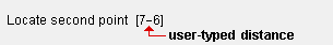
To constrain the distance: Simply type, at your keyboard, the distance that you want the second point to be constrained to (e.g., type 7-6 ). The distance entered must be in the primary dimension " Units ." Your entry will be plotted in the status line inside of brackets [ ]. You can use the Backspace key to erase the entry and release the constraint.
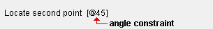
To constrain the angle: You can also type in @ number to constrain the second point to the number of degrees that you enter (e.g., type @45 ). A constraint of 0 degrees is horizontal across the screen through the first point that was located.
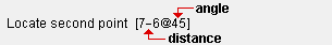
To constrain a distance and angle: First type the distance (e.g., 7-6 ), then type @ , then type the number of degrees (e.g., 45 ). For the example shown, the second point will be located 7.5 ft away from the first point, at an angle of 45°.
Also see: User and Site Options > General > "
Disable typed dimensions during point location " disables the capability to type in a distance and/or angle.
Entering angles :
Degree entries are rounded to the nearest ten thousandth of a degree. For example, 10.00029 is rounded to 10.0003 .
0 degrees designates no rotation. An item that is not rotated is normally horizontal across the screen. Rotation of Drawing Editor objects such as construction lines is done with respect to screen axes . Rotation of Modeling members and materials is done with respect to global axes .
Negative degrees designates a clockwise rotation from the zero degree position of the object.
Positive degrees designates a counterclockwise rotation from the zero degree position of the object.

