 VRML Export - Model
- General Overview
- Step-By-Step
- Tips and Tricks
- Related Tools
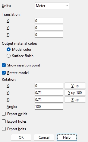
Units: Inch or Meter. When Inch is selected, the VRML file stores distances in inches, but most VRML viewers assume distances are in meters, so the model appears much larger than its real size. If you select Meter, Export Model converts all distances to meters so the VRML model displays at the correct, real-world scale, because the file’s units match the VRML standard.
Translation: 0 or a positive/negative distance. Each member’s work points have specific global X, Y, and Z coordinates at both ends in the 3D model. To move all members in the exported file by a set amount along X, Y, and/or Z, enter that distance here.
0for X and Y and Z exports a model with the same origin ( 0, 0, 0 global coordinate ) as the model in your current Job.
A positive distanceadds to the X, Y or Z coordinates of all exported members.
A negative distancesubtracts from the X, Y or Z coordinates of all exported members.
Output material color:Model color or Surface finish. When Model color is selected materials will be output in the color shown in the model. Generally, this will be the Color that is selected on their material edit windows or, if you are exporting while in Modeling , their status display colors. Select Surface finish to output materials in a color that matches the Surface finish that is selected for those materials on their material edit windows.
Show insertion point: ![]() or
or ![]() . The insertion point in a VRML file may be identified with a cone. If this box
. The insertion point in a VRML file may be identified with a cone. If this box ![]() is checked, the cone will be shown. If the box
is checked, the cone will be shown. If the box ![]() is not checked, the cone will not be shown.
is not checked, the cone will not be shown.


insertion point
Rotate model: ![]() or
or ![]() . If this box
. If this box ![]() is checked, the members are exported with transformations that follow the Rotate settings. If the box
is checked, the members are exported with transformations that follow the Rotate settings. If the box ![]() is not checked, the members are exported with the Z axis (the elevation axis) pointing up, and the Rotate options are disabled (grayed out).
is not checked, the members are exported with the Z axis (the elevation axis) pointing up, and the Rotate options are disabled (grayed out).
Rotation: User specified, Y up, Y up 180, or Z up. This applies only if ![]() Rotate model is checked. The global coordinate systems of modeling software typically have X, Y and Z axes. In other software, the Y axis may be the elevation axis. To enter a User specified transformation, type in the exact X, Y, Z values andAngle that you want. Y up exports the model with transformations in the file that make the Y axis point up. Y up 180 is the same as Y up, but rotates the model 180 degrees. Z up maintains the model orientation that exists in the SDS2 3D model, which would be the same as leaving
Rotate model is checked. The global coordinate systems of modeling software typically have X, Y and Z axes. In other software, the Y axis may be the elevation axis. To enter a User specified transformation, type in the exact X, Y, Z values andAngle that you want. Y up exports the model with transformations in the file that make the Y axis point up. Y up 180 is the same as Y up, but rotates the model 180 degrees. Z up maintains the model orientation that exists in the SDS2 3D model, which would be the same as leaving ![]() Rotate model unchecked.
Rotate model unchecked.
Applications : If you are exporting this file in order to integrate an SDS2 VRML model with another VRML model, the coordinate systems in the two VRML files need to match. For example, if you export using Y up and find that the resulting imported model does not properly align with a model imported from another package, you might try exporting the file again, but this time using Y up 180.
Export welds: ![]() or
or ![]() . If this box
. If this box ![]() is checked, welds are output to the VRML file. If this option
is checked, welds are output to the VRML file. If this option ![]() is not checked, welds will not be included in the export file.
is not checked, welds will not be included in the export file.
Export holes: ![]() or
or ![]() . If this box
. If this box ![]() is checked, holes are output to the VRML file. If the box
is checked, holes are output to the VRML file. If the box ![]() is not checked, holes will not be included in the export file.
is not checked, holes will not be included in the export file.
Export bolts: ![]() or
or ![]() . If this box
. If this box ![]() is checked, bolts are output to the VRML file that will be generated when you press OK on the Export Model window. If the box
is checked, bolts are output to the VRML file that will be generated when you press OK on the Export Model window. If the box ![]() is not checked, bolts will not be included in the export file.
is not checked, bolts will not be included in the export file.
OK: Applies the changes made to settings on the window to the output of the VRML file.
Cancel: Click Cancel to keep only the settings that were active when you first opened this window; any changes made since then will be discarded and not used.
1. Invoke VRML Export using the Find Tool by searching the command name and clicking the icon, which is pictured above.
Learn more about alternative methods for launching commands.
2. The status line prompts, "Select members". Select one or more members you want to be included in the export, then press the Enter key or right-click and choose OK on the context menu.
Alternative: Right-click and select Cancel or press the Esc key to end the VRML Export at any time.
3. The VRML Properties window opens. Set the export properties, select ok and browse to the Destination where you want the file to be exported and click OK. The model is now exported as a .wrl file.

