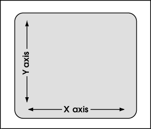
Screen Axes

|
Screen axes are oriented with respect to your computer screen, which is flat & 2D and remains flat & 2D no matter what view you Open ( Ctrl + o ) in Modeling . This means that screen axes are the same in a plan view , isometric view or elevation view . In a plan view, global axes directly correspond to screen axes.
|
- The X screen axis is horizontal across your computer screen (+ is to the right, - toward the left).
- The Y axis is vertical (+ is up, - down).
- The Z axis is perpendicular to the surface of the screen and goes into and out of the screen (+ is toward you, up from the screen; - is away from you).
page 1 | contents | topics | top
Operations that relate to screen axes :
- The DXDY Locate option lets you locate a point by specifying a distance from a first point or a reference point along the X, Y and/or Z screen axes.
- When ANGL is used (for instance, when adding construction lines), you define the rotation of the item being added with respect to the screen.
- " Base Off .. " options such as BSCL , BSRL , BSMB , BSGL can be used to ascertain the angles of linear objects such as construction lines, lines, member lines, grid lines. These angles are reported with respect to screen axes.
- Member Copy X-axis and Y-axis dimensioning is set with respect to screen axes.
- Material Copy X-axis and Y-axis dimensioning is set with respect to screen axes.
- The default coordinate system for rotating an assembly operation is, by default, screen axes .
- Cut on Plane and Cut Layout let you draw lines across a material with your mouse in order to cut the material in a pattern established by those lines. The cuts are made perpendicular to the surface of your computer screen.
- Offset Controls can optionally be set to function with respect to screen axes or global axes .
- CNTR finds the point that is at the exact center of your screen.
- Depth checking controls how far into and out of a screen you can see.
- A temporary construction line may be generated at 45° screen coordinate increments through a noticed point when the Locate option INCL or ONLN or INCM or INCR is used for second point location. If the UCS is toggled on, and the UCS plane is parallel with the screen axes, the temporary construction lines will align, at 45° increments, with the UCS .
- When UCS axes are not shown (off), the user coordinated system (UCS) is off, and ORTHO will use screen axes , not UCS axes , to locate points.
- Rotation of items such as construction lines, weld symbols, etc. is done with respect to screen axes, with 0 degrees being horizontal across the screen.
page 1 | contents | topics | top


