 Connection Cube Isolation
- General Overview
- Step-By-Step
- Related Tools
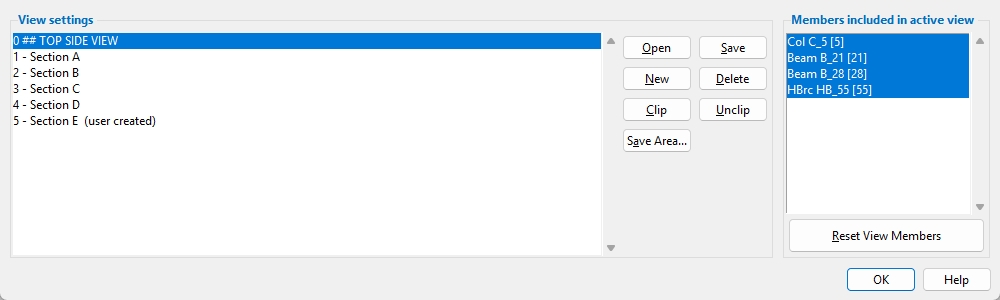
View settings: A list of the Connection Cube views that were automatically created or user-created.
Open: Opens the view you currently have selected in the View settings list. Alternatively, you can double left-click the view to open it. The view you open is also referred to as the active view.
Save: Saves changes you make to the active view. Changes can include depth checking, view rotation, included members, and more.
New: Adds a new cross-sectional view to the Connection Cube. Left-click (Locate) the first point and then left-click (Locate) a second point to create the view.
Delete: Opens a selection list of the non-active views. Select one or more views and click OK to delete them.
Clip: Adds a clipping boundary to the active view. The boundary determines which 2D polygons are included and excluded when the Connection Cube is detailed. To do a Clip operation:
1. Press the Clip button.
2. Hold down the left mouse button and drag the mouse pointer to form an area box around the objects you want to include (or exclude) in the 2D detail when you detail the Connection Cube.
3. The Modify Connection Cube View window opens, select one of the following:
Alternative 1: Press Inside to include the objects inside of the area box and exclude the objects outside of the area box.
Alternative 2: Press Outside to include the objects outside of the area box and exclude the objects inside of the area box.
Alternative 3: Press Cancel to end the Clip operation without changing anything.
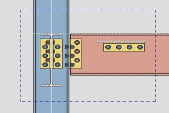
When you press Inside: A simple dashed box marks the area that will be drawn on this particular view when you detail the Connection Cube.
When you press Outside: A dashed box with an X marks the area that will not be drawn on this particular view when you detail the Connection Cube.

Unclip: Removes the clipping boundary from the active view.
Save Area: Performs a Save Area operation. The view you create from this window is not added to the Connection Cube. It is stored as an Erection view that can be opened in Modeling or detailed and opened in Drawing Editor.
Members included in active view: A list of all members shown in the active view. Selected members are shown in the active view. Deselected members are hidden in the active view. Save the active view in order to keep any changes you make to this list.
Reset View Members: If you change the Members included in active view, and you have not saved the active view yet, pressing this button restores the Members included in active view list to the original state it was in when you first opened the active view.
Important: Make sure the display of Connection Cubes is turned on in Display Options prior to using this command.
1. Preselect a Connection Cube to enable the Connection Cubes contextual page and click the Connection Cube Isolation icon found in the Display section.
Alternative: Invoke Connection Cube Isolation using the Find Tool by searching the command name and clicking the icon, which is pictured above. Then click on the Connection Cube you want to isolate.
Learn more about alternative methods for launching commands.
2. The Connection Cube Isolation window appears. When you are done using this window, click OK to complete the operation.
Alternative: If there are unsaved changes made to the active view, you will be prompted to either Save the changes, create a New View, or you can click Cancel to end the operation without saving the changes.

