 Display Options
Opens a window that lets you turn on or off the display of items in the model when using Modeling or Manual Erection View Detailing.
- General Overview
- Tips and Tricks
- Related Tools
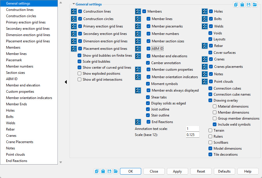
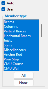
Display filters are available for certain
General settings options when they are
checked Option Name.
To access the display filters for a particular option, select that option in the tree. In this example, Members is selected in the tree. When that option is deselected in the tree, the display filters are no longer shown, but the filters still apply to the display of items in the model. When display filters for an option are non-default, that option's name turns red. Pressing the option's In Manual Erection View Detailing,
Select All buttons and asterisks (*) in front of their option names.
General settings
If this box
If the box
is not checked, construction lines are hidden.
Display filters set the types of construction lines that will be shown when
Pressing the
Also See:Finite line & Pen color
If this box
If the box
Display filters set the colors of construction circles that will be shown when
Pressing the
Primary erection grid lines: ![]() or
or ![]() . This applies to both straight and curved grid lines.
. This applies to both straight and curved grid lines.
|
Grid line = erection view
Erection view type = Primary |
If this box
If the box
Display filters are all selected by default, resulting in all primary erection grid lines being displayed when Deselecting certain filters prevents certain grid lines from being displayed. Pressing the Note: When you open this window in the Manual Erection View Detailing program, the choice you make to this option will be applied to the erection view when it is auto detailed.
Also See:Curved Grid lines, Finite Grid lines, pen color, Grid line type, View name
Secondary erection grid lines: ![]() or
or ![]() .
This applies to both straight and curved grid lines.
.
This applies to both straight and curved grid lines.
|
|
Grid line = erection view
Erection view type = Secondary |
If this box
If the box
Note: When you open this window in the Manual Erection View Detailing program, the choice you make to this option will be applied to the erection view when it is auto detailed.
Dimension erection grid lines: ![]() or
or ![]() .
This applies to both straight and curved grid lines.
.
This applies to both straight and curved grid lines.
|
|
Grid line = erection view
Erection view type = Dimension only |
If this box
If the box
Note: When you open this window in the Manual Erection View Detailing program, the choice you make to this option will be applied to the erection view when it is auto detailed.
Placement erection grid lines: ![]() or
or ![]() .
This applies to both straight and curved grid lines.
.
This applies to both straight and curved grid lines.
|
|
Grid line = erection view Erection view type = Placement only |
If this box
If the box
Note: When you open this window in the Manual Erection View Detailing program, the choice you make to this option will be applied to the erection view when it is auto detailed.
Show grid bubbles on finite lines: ![]() or
or ![]() . This applies to finite grid lines.
. This applies to finite grid lines.
If this box
If the box
Scale grid bubbles: ![]() or
or ![]() . This applies to finite grid lines when grid bubbles are shown.
. This applies to finite grid lines when grid bubbles are shown.
If this box
If the box
Show center of curved grid lines: ![]() or
or ![]() .
.
|
|
Tip: Regardless of the choice made here, the center of a curved grid line is always selectable as an exact point. |
If this box
).
If the box
Show exploded positions: ![]() or
or ![]() . To set a member's exploded position, see Set Exploded View Positions. To regenerate an erection view with members shown in exploded positions, see Exploded erection view.
. To set a member's exploded position, see Set Exploded View Positions. To regenerate an erection view with members shown in exploded positions, see Exploded erection view.
When this box
If the box
Tip: If all you want to do is double check the exploded positions of members, select this option then use the Apply button to see what you get, then deselect this option and press OK. Members will be redrawn in their actual 3D positions and all Modeling tools will be enabled.
Show all grid intersections: ![]() or
or ![]() . This applies to isometric views of the model.
. This applies to isometric views of the model.
When this box
If the box
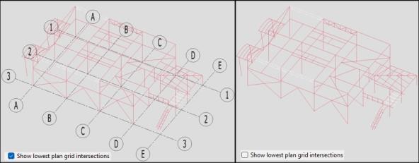
Show lowest plan grid intersections: ![]() or
or ![]() .
.
If this box
If the box
If this box
If the box
Display filters are all selected by default, resulting in all members not hidden by other options on this window being displayed when Deselecting certain filters prevents certain members from being displayed. Pressing the Also See:Existing member
Member lines: ![]() or
or ![]() . This applies to members in stick form.
. This applies to members in stick form.
If this box
If the box
Display filters are all selected by default, resulting in member lines being displayed when Deselecting certain filters prevents certain member lines from being displayed. Pressing the Also See:Member lines
If this box
If the box
Note: If a member has not yet been assigned a piecemark, member numbers are displayed instead of piecemarks. Try processing the model to assign piecemarks.
Display filters are all selected by default, resulting in member piecemarks being displayed when Deselecting certain filters prevents certain member piecemarks from being displayed. Pressing the
If this box
If the box
If this box
If the box
Custom member section sizes: Not all custom members can have their section sizes displayed. The plugin for a custom member must include the GetSectionSize method in order for the section size of that custom member to be displayed.
ABM ID: ![]() or
or ![]() . The main material of a member may be assigned an ABM ID when a new ABM is created or an existing ABM is Updated.
. The main material of a member may be assigned an ABM ID when a new ABM is created or an existing ABM is Updated.
If this box
If the box
Member end elevations: ![]() or
or ![]() . This applies to plan views when Show elevation on member is set to Reference in Home > Project Settings > Fabricator > Detail Erection View Defaults. It applies to plan views, elevation views and isometric views when Show elevation on member is set to Absolute.
. This applies to plan views when Show elevation on member is set to Reference in Home > Project Settings > Fabricator > Detail Erection View Defaults. It applies to plan views, elevation views and isometric views when Show elevation on member is set to Absolute.
For this example, Show elevation on member was set to Reference. The displayed value of (+9 1/2) is the offset of the member work point from the reference elevation of the plan view.
For this example, Show elevation on member was set to Absolute. Since both ends of the member are at an elevation of 114-6, the value is shown in the middle of the member. If this box
If the box
If this box
If the box
Note: To get a camber annotation, the Rolling operation must be set to Camber annotation or to Camber (Both) and the Mid-ordinate must be a non-zero value.
Member custom properties: ![]() or
or ![]() .
.
If this box
If the box
Schema Add/Edit: Erection View Member Labels
Setup: Erection View Member Labels
Detail Erection View Defaults window: Custom properties on member
Erection View Cleanup window: Member custom property
Member orientation indicators: ![]() or
or ![]() . This applies to members in stick form in Modeling that are in plan views and elevation views. In Manual Erection View Detailing, this applies to Stick + wire members as well as to stick-form members and it affects the resultant drawing.
. This applies to members in stick form in Modeling that are in plan views and elevation views. In Manual Erection View Detailing, this applies to Stick + wire members as well as to stick-form members and it affects the resultant drawing.
If this box
If the box
Display filters are, by default, all selected, resulting in member orientation indicators being displayed when Deselecting certain filters prevents certain orientation indicators from being displayed. Pressing the Detail Erection View Defaults window:Member orientation indicators
Erection View Cleanup window: Show member orientation indicator
Moment symbols: ![]() or
or ![]() . This applies to beams with
. This applies to beams with ![]() Moment connections that are displayed in stick form.
Moment connections that are displayed in stick form.
If this box
If the box
Member ends always displayed: ![]() or
or ![]() .
.
If this box
If the box
Display filters set which member ends will be shown when
Pressing the
Shear tabs: ![]() or
or ![]() . This applies to plan views when beams with single-plate shear connections are displayed in stick form.
. This applies to plan views when beams with single-plate shear connections are displayed in stick form.
If this box
If the box
Detail Erection View Defaults window: Show shear tab location on erection views
Erection View Cleanup window: Left end shear tab symbol, Right end shear tab symbol
If this box
If the box
User and Site Options: Modeling > Color settings > 3D wire frame outline color
Joist outline: This applies to joists in stick form.
If this box
If the box
Stair outline: This applies to stairs in stick form.
If this box
If the box
If this box
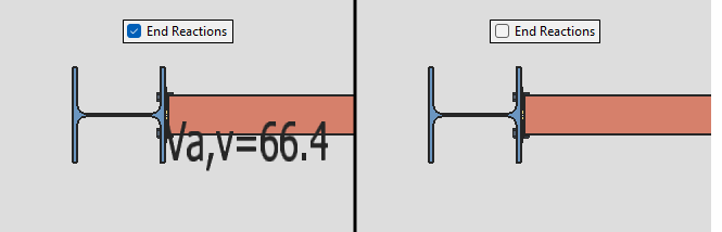
Loads leaf are displayed at the respective member end.
If the box
Display filters set which end reactions will be shown and which member type(s) show them when
Pressing the
Project Settings: Fabricator > Detailing > Erection View Member Labels > Reaction Nomenclature
If this box
If the box
Annotation text scale: The scale of the point location annotation text. This scale applies to the dimension that is shown when you locate a second point with ANNO turned on. The scale also applies to the text that identifies the operative snap mode and to the dimension labels for Model dimensions.
Example 1: An Annotation text scale of 1 is the default. If you double the Annotation text scale, the text will be twice as high and twice as wide. Be aware that the text always stays this same size, regardless of how much you zoom in or zoom out.
Example 2: If you double the Scale of your current view (e.g., from 0.125 to 0.25), the annotation text is halved since the same number of pixels will now equal twice the distance. You would need to double the Annotation text scale if you wanted to make the annotation text be the size that is was before you doubled the Scale.
To turn off annotation text, set the Annotation text scale to 0. To stop the dimension from being shown, turn ANNO off.
Scale (base 10 or base 12): The scale at which the detail of your current view will be regenerated when you Detail Erection Views for the first time (see the note below). This option also affects the size of piecemarks and section sizes relative to materials in your current view (but does not affect their actual printed size, which is set in Drawing Presentation).
This scale is in base 12 if you are using imperial... dimensioning, in base 10 if you are using Metric dimensioning. The normal default for imperial dimensioning (base 12) is 0.125.
Example 1: If you are using imperial dimensioning and you use the default of 0.125 here, then the scale will be 0.125 inches = 1 ft.
Example 2: If you are using metric dimensioning and you want to get a drawing scale of 1:100, you would enter 0.1 here.
Example 3: If you use 0.125 as your base 12 (imperial) scale and you want the exact equivalent to be used for metric drawings, you would enter 0.1042 here, since (.125 / 12) * 10 = 0.1042.
Tip: Scale applies to your current view only. Changes made to Scale are lost when you exit the view. To make your changes permanent, you need to Save View As.
Note: Changing the scale here does not affect the drawing of this view if that drawing . The Drawing scale in the Drawing Editor sets the scale of an erection view without your having to re-detail the erection view. If you change the Drawing scale in the Drawing Data Panel, then Open that erection view in Modeling (so that it is your current view), the new drawing scale is displayed here.
Holes: ![]() or
or ![]() . This applies to 3D holes on submaterials of members that are in a solid form.
. This applies to 3D holes on submaterials of members that are in a solid form.
If this box
If the box
Display filters are, by default, all selected, resulting in all categories of holes having the potential to be displayed when Deselecting certain filters prevents certain holes from being displayed. Pressing the Also See: System holes
Bolts: ![]() or
or ![]() . This applies to 3D bolts on members which are displayed in a solid form. It does not apply to material bolts.
. This applies to 3D bolts on members which are displayed in a solid form. It does not apply to material bolts.
If this box
If the box
Display filters are, by default, all selected, resulting in all categories of bolts potentially being displayed when Deselecting certain filters prevents certain bolts from being displayed. Pressing the Also See: System bolts
Welds: ![]() or
or ![]() . This applies to 3D welds on members in a solid form.
. This applies to 3D welds on members in a solid form.
If this box
If the box
Display filters set which welds will be shown when
Pressing the
Voids: ![]() or
or ![]() . Voids remove material from members. They can be added using custom members such as Void Space Cylinder and Void Space Layout. They can also be added by custom components such as Web Penetration with Stiffeners and Void Space Cylinder and Void Space Layout.
. Voids remove material from members. They can be added using custom members such as Void Space Cylinder and Void Space Layout. They can also be added by custom components such as Web Penetration with Stiffeners and Void Space Cylinder and Void Space Layout.
If this box
If the box
Layouts: ![]() or
or ![]() . Concrete walls and concrete slabs that are displayed in a solids form have white reference lines that show the member's layout. This may also apply to other custom members.
. Concrete walls and concrete slabs that are displayed in a solids form have white reference lines that show the member's layout. This may also apply to other custom members.
If this box
If the box
If this box
If the box
If this box
If the box
If this box
If the box
Display filters are all selected by default, resulting in all categories of cranes having the potential to be displayed when Deselecting certain filters prevents certain cranes from being displayed. Pressing the
If this box
If the box
Display filters set the names of crane placements that can potentially be shown when
Pressing the
If this box
If the box
Tip: Notes with

Display filters are all selected by default, resulting in all categories of notes that are not project notes having the potential to be displayed when Deselecting certain filters prevents certain notes from being displayed. Pressing the
If this box
If the box
If this box
If the box
If this box
If the box
If this box
If the box
Before material dimensions can be shown: Detail Submaterial is required, the detail must be up to date, and the material must be displayed in solid form.
If this box
If the box
An alternative to this option is to use Show Dimensions, which keeps displaying the dimensions until you Clear Dimensions. Show Dimensions also allows you to display dimensions on more than one material.
Before member dimensions can be shown: Detail Members is required, the detail must be up to date, and the member must be displayed in a solid form.
If this box
If the box
An alternative to this option is to use Show Dimensions, which keeps displaying the dimensions until you Clear Dimensions. Show Dimensions also allows you to display dimensions on more than one member.
Before group member dimensions can be shown: Detail Member Groups is required and the group member must be displayed in a solid form.
If this box is checked (
If the box
An alternative to this option is to use Show Dimensions, which keeps displaying the dimensions until you Clear Dimensions. Show Dimensions also allows you to display dimensions on more than one group member.
Include weld symbols: ![]() or
or ![]() . This applies when
. This applies when ![]() Member dimensions or
Member dimensions or ![]() Material dimensions or
Material dimensions or ![]() Group member dimensions are shown.
Group member dimensions are shown.
|
If this box
If the box
If this box
If the box
User and Site Options: Modeling terrain
Setup: Top of terrain (global coordinate positioning of the terrain)
Setup: Thickness of terrain
 |
Rulers shown in an elevation view. The rulers display global coordinates, expressed in the primary dimension Units. |
If this box
If the box
User and Site Options:Modeling > Display settings > Rulers active sets whether rulers are turned on or off for each time you start up Modeling.
If this box
If the box
User and Site Options: General > Display settings > Scrollbars active sets whether scrollbars are turned on or off for each time you start up Modeling.
Model dimensions: These are dimensions that have been added to the model using Add Model Dimensions, Dimension Members, or Dimension Clearance.
If this box
If the box
Also see: The Annotation text scale on this window (Display Options) sets the size of a model dimension's label.
Tile decorations: ![]() or
or ![]() . Tile decorations are tile tools.
. Tile decorations are tile tools.
|
From left to right, the tile decorations in this example are Toggle Active Tile, Split Tile Vertically, Split Tile Horizontally Single Tile and Four Tiles |
If this box
If the box
User and Site Options:General > Display settings > Tile decorations active sets whether tile decorations are turned on or off when you launch a new Modeling session.
![]() Copy, Paste, Save, Load buttons:
Copy, Paste, Save, Load buttons:
- The position of these "form" buttons on the window tells you what settings they apply to. Click here for more information.
- You can
 Copy the settings on this window, then
  Paste those settings to a different edit window of the same type.
- You can
 Save the settings on this window to a file stored in a global folder that is used by your current version of SDS2. Give the file a name that will help other users identify its purpose. You can
  Load a saved file to replace the settings on this window (except Piecemark) with the settings that are stored in the file you select.
- When editing multiple windows at the same time, Paste and Load replace mixed entries to a single field with a single entry. Copy and Save ignore fields with mixed entries, treating them as if they have no entry or do not exist.
![]()
![]()
![]()
![]()
![]()
OK (or the Enter key) closes this window and redraws your computer screen according to the settings on it.
With the exception of Scale, all Display Options remain in effect from the first redraw, and as you change from view to view. They also remain in effect if you Exit Modeling then start up Modeling again.
Cancel (or the Esc key) closes the Display Options window without saving any of the changes you made to it since you originally opened it or last pressed Apply.
Apply redraws your computer screen to show the results of any changes you have made on this window. The window does not close, and you can make additional changes to the window before you press OK.
Please note that once you press Apply, any selections made since you originally opened this window are saved, which means that Reset will no longer undo those selections.
Reset undoes all changes made to the Display Options window since you first opened it or last pressed Apply. The window remains open.
Defaults resets all display filters to their default values. It also checks ( ![]() ) and unchecks (
) and unchecks ( ![]() ) options on this window to reset them back to their defaults.
) options on this window to reset them back to their defaults.
Tip: Visually some of the results of pressing the Defaults button are indicated by options changing from red to black. For example, if the options
Warning: Pressing the Defaults button can potentially make changes to almost every option on this window.

