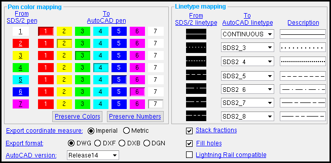
 The Drawing Export Configuration window ( Fabricator Settings )

Some settings applied to this window can be overridden during Drawing Conversion . The pen color and linetype mapping options cannot be overridden.
- Setting up user linetypes
- " OK " " Cancel " " Reset "
Also see :
- Drawing Conversion (set up by this window)
- Home > Export > 2D > Export Cad Drawing (to apply choices on this window)
- Home > Export > Transmittal > select "Sheet Items" (alternative way to export drawings)
Please note :
- Settings applied here, on the Drawing Export Configuration window, are for your current Fabricator . When you " Change Fabricator , " you change to a different set of Drawing Export Configuration settings.
page 1 | contents | home > export > 2D > click the gear
![]() Setting up user linetypes :
Setting up user linetypes :
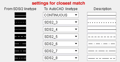
- This example shows you how to set the linetype options on this window so that a Drawing Editor drawing converted to a .dxf, .dxb or .dwg file using Drawing Conversion is as close as possible to the original.
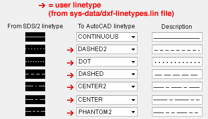
- The following example shows several SDS2 linetypes that have been set up to be output as user linetypes.
- A .dxf, .dxb or .dwg file can contain a larger set of linetypes than are available for use in SDS2. To convert an SDS2 linetype to an AutoCAD linetype that is not available in SDS2, you need to:
1 . Create a .lin file in AutoCAD or a similar program.
2 . Name the .lin file dxf-linetypes.lin and place it in the sys_data directory.
3 . On the Drawing Export Configuration window (this window), select the user linetype in the " To AutoCAD linetype " column so that it is applied to the appropriate " SDS2 linetype ."
4 . Export a drawing as a .dxf, .dxb, or .dwg file. All lines will be converted as you have specified.
page 1 | contents | home > export > 2D > click the gear | top
 Step-by-step instructions :
This window ( Drawing Export Configuration ) lets you set the AutoCAD version, line types, and pen colors of the file that is output when you export a Drawing Editor drawing as a .dxf, .dxb, .dwg or .dgn file. For a Home > Drawing Conversion > press " Export " operation, this window sets the defaults, which can be overridden on the Drawing Conversion window. For a Home > Export > Transmittal > select " Sheet Items " operation, any .dxf, .dwg and/or .dgn files that are exported are configured per the choices made here, on the Drawing Export Configuration setup window.
1 . Open the Drawing Export Configuration window using any one of the following methods:
Method 1 : Home > Export > click the gear (
) next to Export CAD Drawing .
2 . Optionally apply " Pen color mapping " options by doing the following. Or skip this step and go to step 3.
2a (optional) : For each pen shown in the " From SDS2 pen " column, select a pen from the " To AutoCAD pen " column. The pen selected in the " To AutoCAD pen " column is the pen assigned to all graphic elements in to-be-exported Drawing Editor drawings that use the corresponding " From SDS2 " pen. Skip step 3 and go to step 4.

3 . Optionally press the " Preserve Colors " button or the " Preserve Numbers " button. Skip this step if you already applied " Pen mapping " (in step 2).
![]()
3a ( optional ): Press the " Preserve colors " button to cause all graphic elements (CAD objects ) in .dxf, .dxb or .dwg files subsequently exported to be represented on screen (for example, in AutoCAD) in the same color as they are represented on screen in the original Drawing Editor drawings that the files will be exported from.
3b ( optional ): Press the " Preserve numbers " button to cause all graphic elements in .dxf, .dxb or .dwg files subsequently exported from SDS2 to be assigned the same pen number as they are assigned in the original Drawing Editor drawings that the files will be exported from.
4 . Optionally apply " Linetype mapping " options.

4a ( optional ): For each linetype shown in the " From SDS2 linetype " column, select a linetype from the " To AutoCAD linetype " column (also see setting up user linetypes ). The " Description " column shows you how the selected " To AutoCAD linetype " will look in the exported .dxf, .dxb, .dwg or .dgn file.
5 . Select the " Export coordinate measure " that you want.
Export coordinate measure: Imperial or Metric . This option affects the scale of the .dxf, .dxb, .dwg or .dgn drawing and any materials that are depicted on the drawing. It does not affect dimension labels or labels or any other text in the drawing. ' Imperial ' outputs coordinates in decimal inches. ' Metric ' outputs the coordinates in millimeters.
Note: The primary dimension " Units " specified in " Drawing Presentation " are irrelevant to the selection you make here. What is important is the units that the importing program you are exporting to expects. If that program expects the coordinate system selected here, then the drawing will be the same size as it is in the Drawing Editor .
6 . Select the export file format and version that you want to export to and the output method for fractions:
Export format: DWG or DXF or DXB or DGN . These file formats, with the exception of the DGN format, were developed by Autodesk. The DGN format was developed jointly by Intergraph and Bentley Systems. All are recognized by AutoCAD. Choose the file format that you prefer. The next time you Export a Drawing Editor drawing, it will, by default, be output in this format, named after the Drawing Editor file that you select, and given the appropriate extension.
|
|||||||||||||||
| FYI : Drawing Conversion can also import " As Reference Drawing " or " As Job Standard " any of the above-listed export formats. Additionally, Drawing Conversion can also import PDF files. |
AutoCAD version: Unspecified (sets version to minimum) or R10 or R11/R12 or R13 or R14 or 2000 - 2002 or 2004 - 2006 or 2007 - 2009 or 2010 or 2013 . This setting applies to the three Autodesk formats (' DWG ', ' DXF ', and ' DXB '). This is the default export version of the files that are output the next time you Export Drawing Editor drawings. To export ellipses or stack fractions , the version must be ' R13 ' or higher. To export images , the version must be ' R14 ' or higher. Note: After version R14, Autodesk began to name their versions after the years in which they were released. Also see: " AutoCAD version " on the DXF Tool Definition window sets the version for CNC download files when the " CNC type " is ' DXF '.
Stack fractions:
or
. This applies when the " Export format " is ' DXF ' or ' DXB ' or ' DWG ' or ' DGN '. For ' DXF ' or ' DXB ' or ' DWG ', the " AutoCAD version " must be ' R13 ' or greater. Stacked fractions (
) are single text (MTEXT) objects. Non-stacked fractions (
) are distinct numbers separated by a slash.
|
Fill holes:
or
. This applies when the " Export format " is ' DXF ' or ' DWG '. If checked (
), then holes in the exported drawings will be filled in (
). If not checked (
), the holes will be circles that are not filled in (
).
|
Lightning Rail compatible:
or
. If checked (
), the drawing output is unshortened and chiefly consists of the outline layer, without annotations and dashed lines. This provides compatibility with Automated Layout Technology's "Lightning Rail" CNC marking machine for the layout of commercial handrails, and it also may provide compatibility with other technologies that use similarly formatted drawing output . If not checked (
), drawing output more closely matches the original SDS2 drawing.
7 . When you are done making changes to the Drawing Export Configuration window, press one of the following buttons:


"OK" (or the Esc key or the
button) closes this window and saves any changes that you have made to it. The changes are saved to your current Fabricator . The choices made here determine how linetypes and pen colors will be converted the next time you Export drawings as .dxf, .dxb, .dwg or .dgn files using that same current Fabricator .
"Cancel" (or the Esc key) closes the window without saving any changes made to it.
"Reset" undoes all changes made to this window since you first opened it. The window remains open. Follow the instructions on this page beginning with step 2 to apply different settings to this window.
page 1 | contents | home > export > 2D > click the gear | top


