 Drawing Conversion ( Home & Modeling & Drawing Editor )

 |
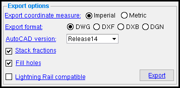
Links under " Export options " on this screen shot direct to help for Home > Project Settings > Fabricator > Drawing Export Configuration . These " Export options " override -- when you " Export " -- the choices made to Drawing Export Configuration . If you are importing -- "As Reference Drawing " or " As Job Standard " -- the " Export options " do not pertain. Each time you open this window, the choices made under " Export options " default back to the choices made in setup. |
- Exporting a Drawing Editor drawing
- Importing files as job standard details or reference drawings (
 )
)
Also see :
- Drawing Export Configuration ( Home > Project Settings > Fabricator > )
- Drawing Import Settings ( Home > Project Settings > Fabricator > )
- Output configurations ( User and Site Options > Output > )
- Job standard details (.dxf, .dxb, .dwg, dgn or .pdf files can optionally be imported as)
- Reference drawings (.dxf, .dxb, .dwg, dgn or .pdf files can optionally be imported as)
- Exporting from your current Job (index)
- Importing items into a Job (index)
- Home > Export > Transmittal > select "Sheet Items" (alternative way to export drawings)
modules | home > import | home > export | interface (classic)
 Drawing Conversion to export a Drawing Editor drawing :
Drawing Conversion can export any type of Drawing Editor drawing. The original Drawing Editor drawings that you select in step 4 are copied then converted to DWG , DXB , DGN or DXF files.
1a (optional) : Verify that the default output configuration entered for User and Site Options > Output > " Drawing Conversion " is the one you want. The output should be set to a directory. This step is optional since the default output destination can be overridden by pressing the button under " Destination " in step 4 .
Directory:
D:/folder/subfolder 
1b (optional) : Review and, if necessary, edit Fabricator Setup > Drawing Export Configuration . In step 3, you can optionally override the choices that you make to Drawing Export Configuration setup.
2 . Invoke Drawing Conversion using any one (1) of the following methods:
Method 1 : At Home , choose Export > Export CAD Drawing .
Method 2 : If " Modeling layout style " or " Drawing Editor layout style " is ' Classic ', you can use the menu system to choose Interface > Drawing Conversion .
Methods 3 & 4 : Click the icon pictured above , or use a keyboard shortcut . The command group for Drawing Conversion is ' Interface '.
An alternative to Drawing Conversion : You can also output drawings using Home >Export Transmittal > select " Sheet Items ."
3 . The Export CAD Drawing window opens.

|
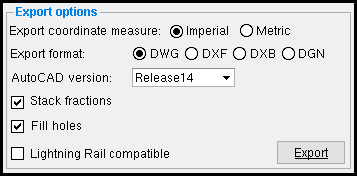
Optionally change the " Export coordinate measure " and/or " Export format " and/or " AutoCAD version " and/or " Stack fractions " and/or " Fill holes " and/or " Lightning Rail compatible ." These options override -- for your current export -- choices made at Home > Project Settings > Fabricator > Drawing Export Configuration . |
Alternative 1 : Press the " Export " button and go to step 4.
Alternative 2 : Press the " Cancel " button to close this window without exporting any drawings.
|
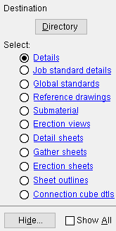
Optionally press the button under " Destination " to redirect the output destination. In this example, " Directory " indicates that the converted drawing files will be output to a particular file folder ( |
4a : Select one (1) of the drawing types shown on the selection dialog, such as
Details or
Job standard details or
Global standards , etc. This sets the type of file that you want to copy and export as .dxf or .dxb or .dwg or .dgn files.
4b : Select the Drawing Editor files that you want to convert, then press the " OK " button. Go to step 5.
Alternative : Press the " Cancel " button to end this operation without converting any files. Do not continue.
5 . Copies of the Drawing Editor files that you selected in step 4 are converted to the selected " Export format " and placed in the directory that you designated in step 1a or step 4. The files are given the same base names as the Drawing Editor files you selected along with the extension .dxf or .dxb or .dwg or .dgn , depending on the " Export format ." If the file has a special character that the operating system does not allow in a file name, that special character is removed from the name. For example, an erection view named EL: 126-0 will be renamed EL 126-0.dwg when exported as a DWG file under Windows.
|
Drawing Conversion is used to export a submaterial ( a1 ) to a DWG file ( a1.dwg ). |
modules | home > import | home > export | interface > | top
 Importing file(s) as job standard details or reference drawings
Items in an individual .pdf , .dxf , .dxb , . dwg or .dgn file are imported into the Drawing Editor as lines, labels, circles or arcs. Dimensions in the file are imported as lines and labels. Entities that are blocked (grouped together) in the file are ungrouped when imported. You may get " Did not import ... " warnings for items that cannot be imported, but all other entities in the file will likely be imported anyway. Each converted job standard detail or reference drawing is, if possible, given the same name as the file it was converted from (minus the file extension). A file name that is longer than 61 characters will, in the converted drawing, be truncated to 61 characters.
| YouTube video: Importing a PDF as a reference drawing .
|
|
1 . Before importing:
1a : If the .dxf , .dxb , .dwg , .dgn , or .pdf files have been compressed, extract them. Place the decompressed files in a location where Drawing Conversion Import can get to them. By default, Drawing Conversion Import opens the data directory that is used by the current version of SDS2 you are running.
1b : Review and, if necessary, edit Home > Project Settings > Fabricator > Drawing Import Conversion .
2 . Invoke Drawing Conversion using any one (1) of the following methods:
Method 1 : At Home , choose Import > Export CAD Drawing .

|
You can choose to import the drawing(s) as reference drawings (alternative 1) or as job standard details (alternative 2). |
Alternative 1 : Press the " As Reference Drawing " button to import the drawing as a reference drawing .
Alternative 2 : Press the " As Job Standard " button to import the drawing as a job standard detail .
Method 2 : If " Modeling layout style " or " Drawing Editor layout style " is ' Classic ', you can use the menu system to choose Interface > Drawing Conversion .
Methods 3 & 4 : Click the icon pictured above , or use a keyboard shortcut .
3 . A file selection window opens so that you can select the files that you want to import.
3a : Confirm the selection for " Files of type " -- select ' Drawing files (all drawing types)', ' Autodesk (*.dwg, *.dxf, *.dxb, *.DXF *.DXF, *.DXB)', ' Bentley (*.dgn, *.DGN)', or ' PDF (*.pdf, *.PDF)'. Or, if the file has is the correct type but has an extension other than those listed, select ' All Files (*) '.
3b : Click folders (
) until you have opened the directory in which the files you want are placed. Then hold down the Ctrl key and select the files (
) that you want. Press the " Open " button.
4 . Drawing Conversion converts the selected .dxf , .dxb , .dwg , .dgn and/or .pdf file(s) into job standard details or reference drawings , depending on the button you pressed in step 2.
4a : A progress bar appears on screen. You may get " Did not import ... " warnings for items that cannot be imported, but other entities in the drawings will be converted. If the drawing cannot be converted, for example, because the version of the file is not recognized, you will be notified of such.
To view the converted drawings: In the Drawing Editor , open the job standard details or reference drawings into which the .dxf , .dxb , .dwg , .dgn and/or .pdf files have been converted. The name of the job standard detail or reference drawing will be the name of the file, minus the extension. The drawing name will be truncated to 53 characters if the original file the drawing was converted from had a name that was longer than 53 characters.
A tip for viewing imported PDF drawings: If your image appears without text or lines in Drawing Editor, open the Layer Panel and hide the PDF Image Layer. This action may reveal text and linework. This is because some PDF files may contain a white background image. Such a file, when imported into a reference drawing, will appear in Drawing Editor to have no text or lines, since they are assigned upon import to a pen that, like the background image, displays white and is obscured by it.
modules | home > import | home > export | interface > | top


