v2022 Enhancements
- Login and License Management
- No Paint Tools
- Handrail Enhancements
- PDF Submittal Tools
- User and Site Options
- Connection Cubes
- Engineering and Connection Design
- Saving Material Fit Operations
- User Experience Updates
Login and License Management
Watch a video tutorial here.
With SDS2’s new cloud-based licensing system, users will need to log in to access their SDS2 software.
When you launch SDS2 2022 for the first time, you will see a login screen asking for that 'User Name’ and ‘Password', which you would have set up via the recent email invitation from licensingdept@sds2.com
Reset password online
If you have forgotten your password, click the “Reset Password” button. This will open id.sds2.com in an internet browser, where you can view and manage your login information.
To reset your password: >Under the Login >area, click "Edit”.
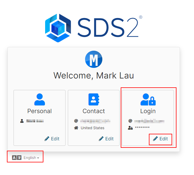
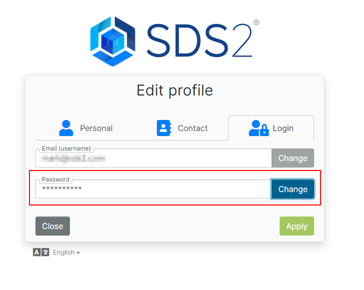
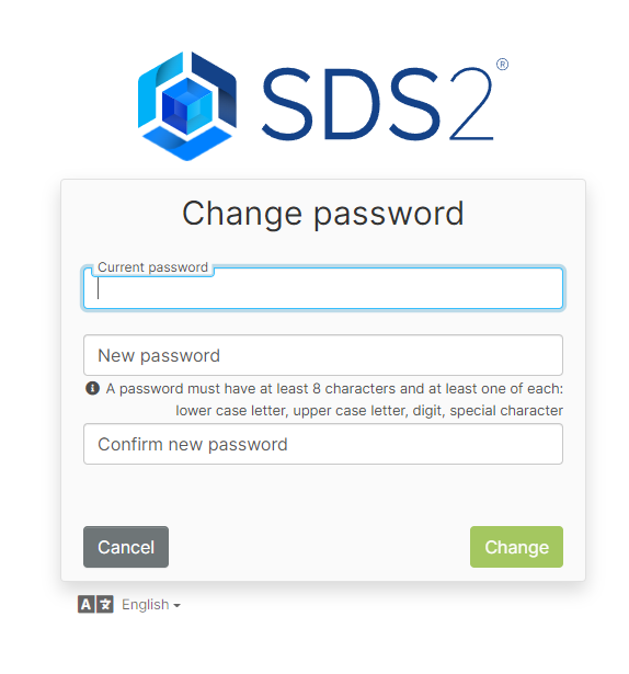
On the 'Password’ field, click the “Change” button to change your password.
Managing your licensing in SDS2
Once you are logged into the SDS2 software, the Home Screen will appear. Here you will notice a new tab called Licensing on the lefthand side of the screen.
Under this tab, you will see information about the “Current license user” and be able to log out if needed—for example, if another user needed to log in to SDS2 on the same computer. The “Org Admin” for your company controls which users have access to which seats of SDS2. For example, one user may have access to Drafting, but not Modeling.
Note: Unless you manually log out on this tab, you will remain logged in, even when you close and reopen SDS2.
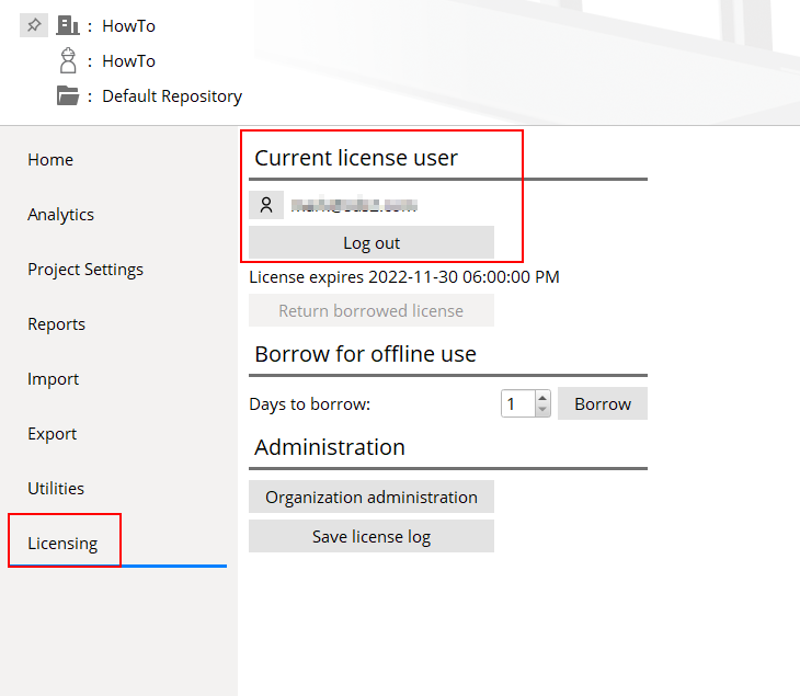
Under the “Log out” button is text that will tell you when the current license expires. This is used in two different ways. In general, it will display the normal expiration date of your license. If you have borrowed a license for offline use, it will indicate how long you can use the license offline before validating with an internet connection.
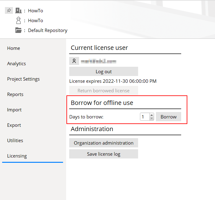
Borrow for offline use
SDS2’s new licensing requires regular validation via internet access. However, users who will be working without internet access can “borrow” licenses for up to 28 days. To do this, simply set the number of days you will be offline, and click the “Borrow” button. A borrowed license is not available for use by anyone else.
Once your “borrow” period is up, you will need to “return” your license by clicking the “Return borrowed license” button while connected to the internet.
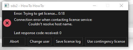
Unexpected loss of internet connection
If SDS2 cannot validate your license through an internet connection, a window will appear with an error message and several options. In the event of an unexpected internet or power outage or other connectivity issues, you can select to “Use contingency license".This will allow you to work offline for up to five days.
Administrative and support options
Additional buttons on the Licensing tab include “Organization Administration", which will direct to the Org Admin portal on the website, and “Save license log", which is used for troubleshooting.
No Paint Tools:
- No Paint and No Paint Layout are tools that add an area of " User created material " to a member so that, when it is auto detailed with templates, it shown outlined with dashed lines. Optionally, member detailing with templates may also be instructed to fill the area with hatch and to label it with "NO PAINT" or other text.
- No Paint tool icons can be taken from the group named ' Model -- Material ' and placed on the ribbon.
- No Paint and No Paint Layout tools are SDS2 Toolbox tools. Such tools are free to users whose support accounts are current. Contact an SDS2 sales representative for more information. To download these tools, log in at https://sds2.com and search (
 ) for "toolbox".
Handrail Enhancements
Watch a video tutorial here.
SDS2 2022 introduces several enhancements to the handrail member.
These include additional options for galvanizing vent holes, fine-tuned control of picket spacing, and the ability to add corner posts and L-shaped base plates. In addition to modeling, improvements have been made to the corresponding detailing templates.
Vent holes for galvanizing
Internal vent holes
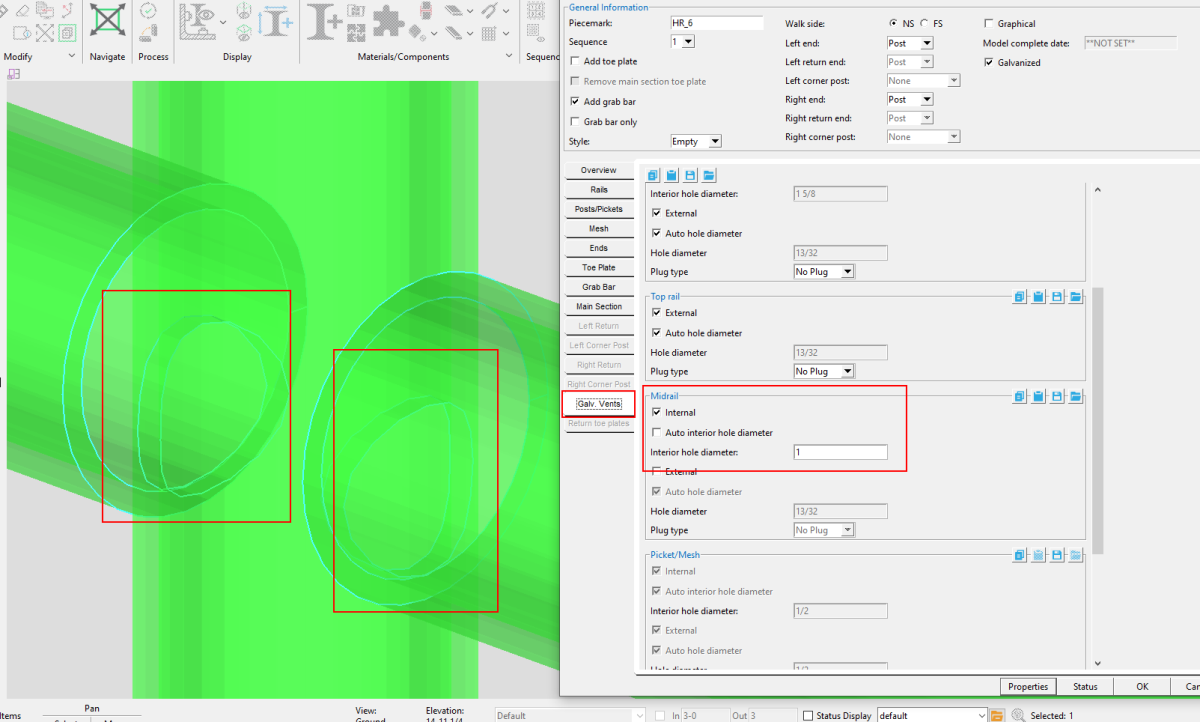
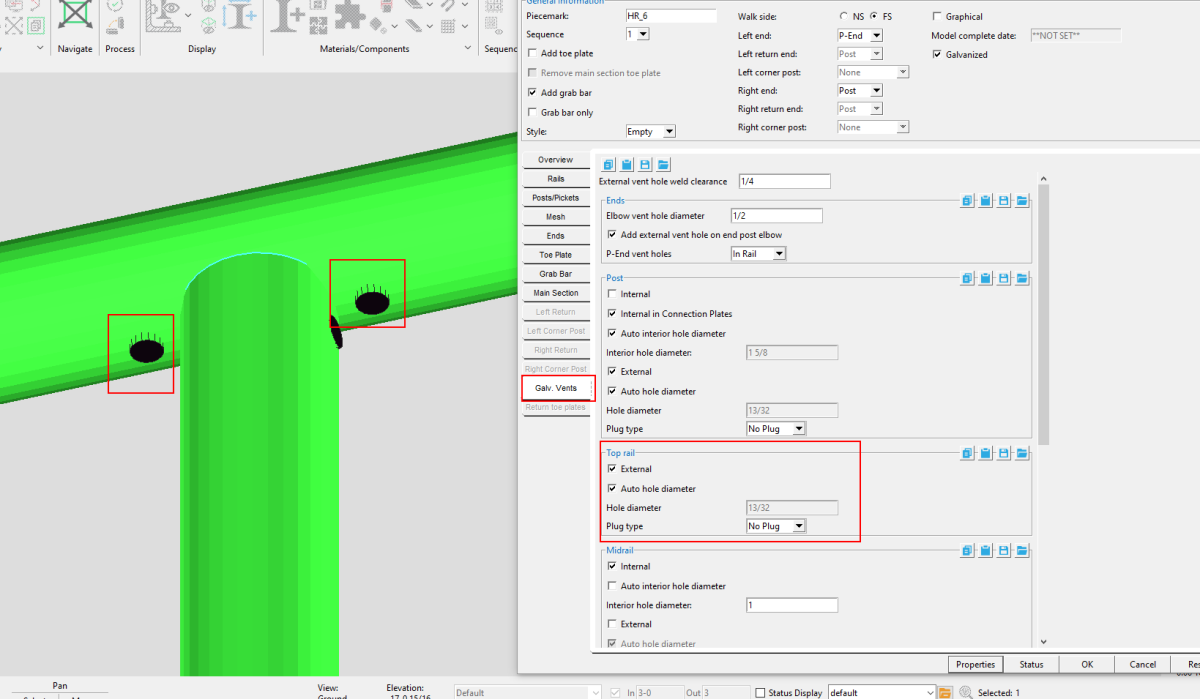
Your handrail edit options now include options to control internal vent hole diameters for posts, midrail, pickets, and grab bar. You can find these in the Hand Rail Edit >window under the Galv. Vents tab.
We have also added a scroll bar to areas of the handrail edit window to make it easier to see and navigate all the options.
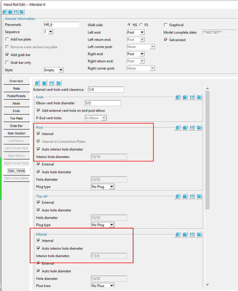
Tip: If you do not fit your post to top rail or midrail to post, the system will create the internal hole at the top rail and post where the midrail ends.
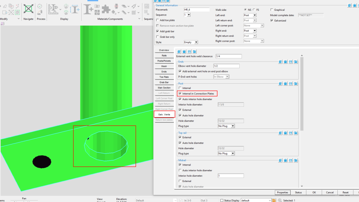
If you check the ‘Internal’ option under “ Posts,” the model will also add an internal hole in the base plate or continuous plate. If ‘Internal’ is deselected, you will be able to select ‘Internal in Connection Plates.” This will allow you to add an internal hole on the plates but not the corresponding top rail or posts at midrails.
External vent holes for galvanizing
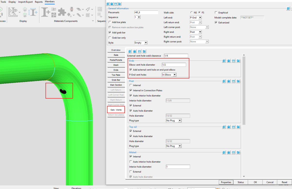
Elbows: In addition to internal vent hole options, you will now see an option under “Ends” to ‘ Add external vent hole on end post elbow’ at the post location. For ‘P-End vent holes,’ you can select to have no vent hole, add one in the elbow, or add one in the rail.
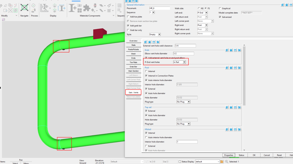
Top rail and posts: There are now options to select or deselect ‘External’ vent holes under both “Posts” >and “Top rail.” This means you now have the option to add external holes to posts while still adding them to top rails.
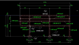
Vent holes on detailing templates
In conjunction with the modeling options for vent holes, improvements have been made to the detailing templates, with internal vents and vent holes labeled.
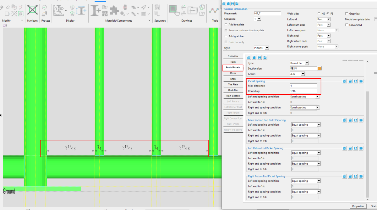
Picket Spacing
Equal spacing for pickets
SDS2 2022 has enhanced the controls for picket spacing, with more automation to make the spacing equal and architecturally pleasing, as well as more user controls.
Options for ‘Max clearance’ will now allow you to set a maximum clearance between post and picket faces. For example, you can set a ‘Max clearance’ of 4 according to OSHA standards to ensure a 4-inch sphere cannot fit between the pickets.
>The ‘Round up’ option can be set to round up the total dimensions between the posts.
Detailing templates – Picket spacing
The Detailing Templates now show the spacing between pickets. These are face-to-face clearance dimensions to the exact 1/16”. If the spacing is not exactly a 1/16”, it will show a (+/-) added to the dimension.
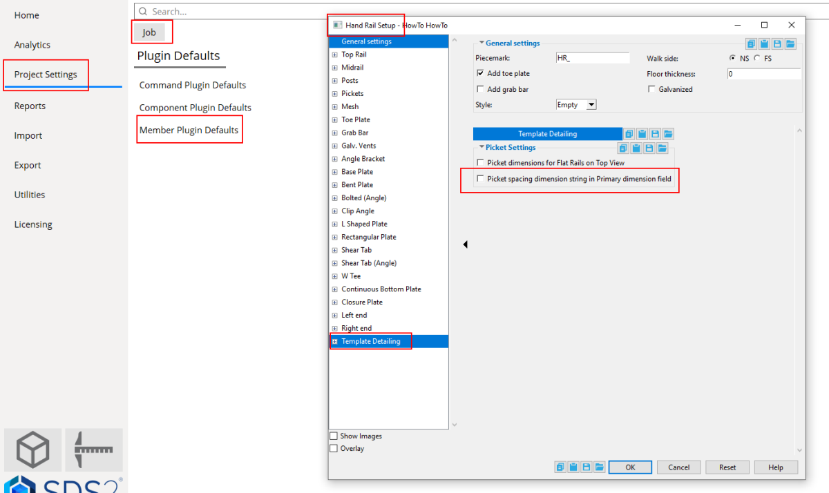
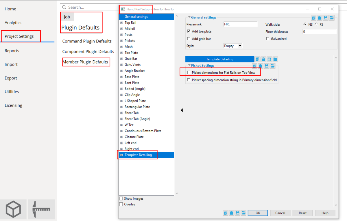
Spacing data has been added to the secondary dimension. An option to include spacing data in the primary dimension field can be found from the Home screen in Project Settings> Job> Plugin Defaults> Member Plugin Defaults> Hand Rail.
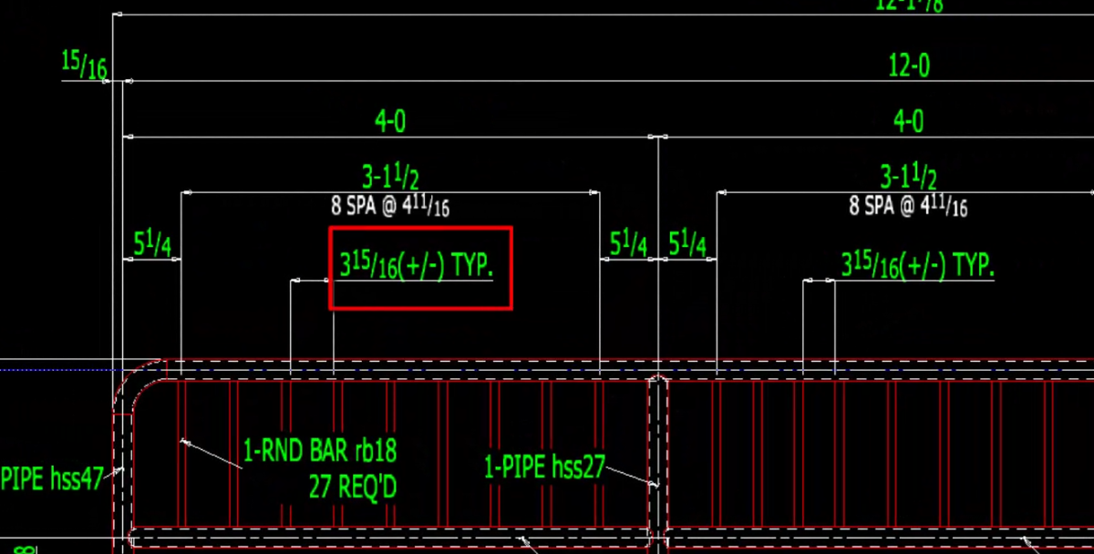
Face-to-face dimension with (+/-) measurementThere has also been spacing data added to the secondary dimension. There is also an option to set the spacing dimension in the Primary dimension. This option is in Project Settings> Job> Plugin Defaults> Member Plugin Defaults> Hand Rail.
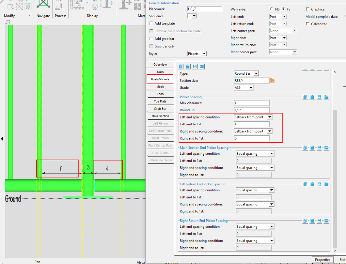
Setback from point
In addition to ‘ Equal spacing’ options for pickets, you can also adjust the spacing from intermediate posts to first pickets.
Left and right end spacing conditions can now be set to ‘Setback from point,’ for pickets, main section ends, and left and right section ends.
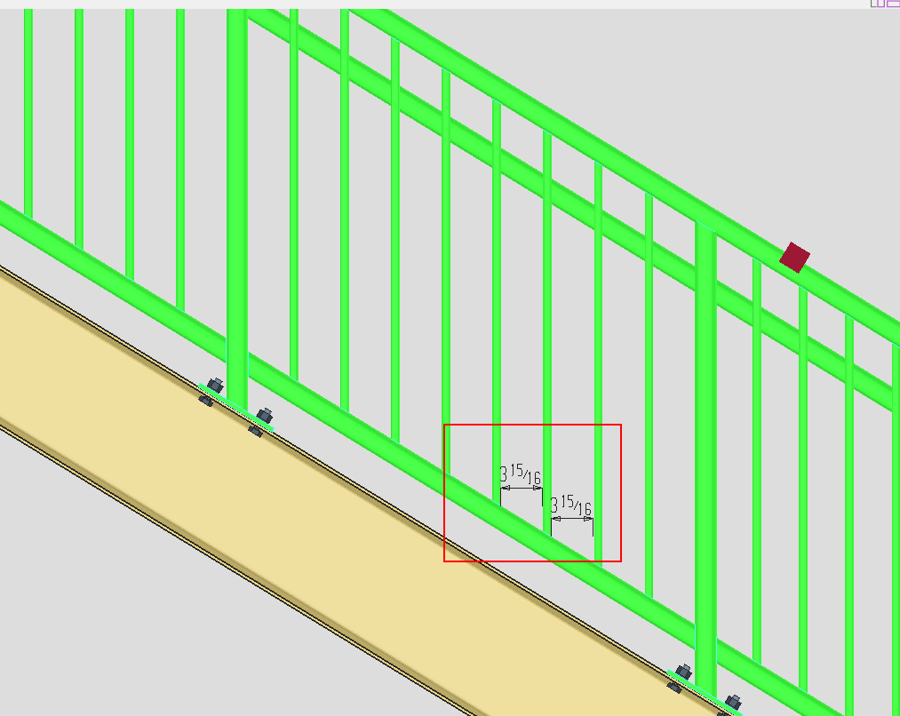
Spacing on slopes
Picket spacing on handrails with a slope will now be calculated on the horizontal, rather than on the slope of the handrail.
Detailing views
When you detail a stair rail with templates, the picket spacing will appear on the Main View if there is not a Top View. If you add a Top View, the picket spacing will automatically be placed on the Top View.
Main View
Top View
For Flat Rails with a Top View, there is an option inProject Settings> Job> Plugin Defaults> Member Plugin Defaults> Hand Rail > Template Detailing to select or deselect ‘Picket dimensions for Flat Rails on Top View.’
Corner Posts
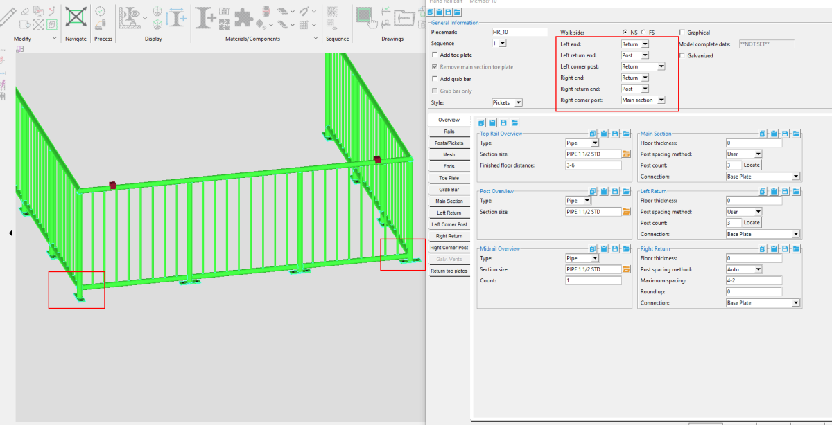
SDS2 now supports adding corner posts with the handrail tool. In the “General Information” area of the Hand Rail edit window, you will see options for ‘ Left corner post’ and ‘ Right corner post.’
You can select from the dropdown menu whether you want the corner post to line up with ‘Main section’ or the ‘ Return,’ which affects the orientation of the connection. For example, if ‘Left corner post’ is set to ‘Return,’ the base plate will run in the same direction as the left return section.
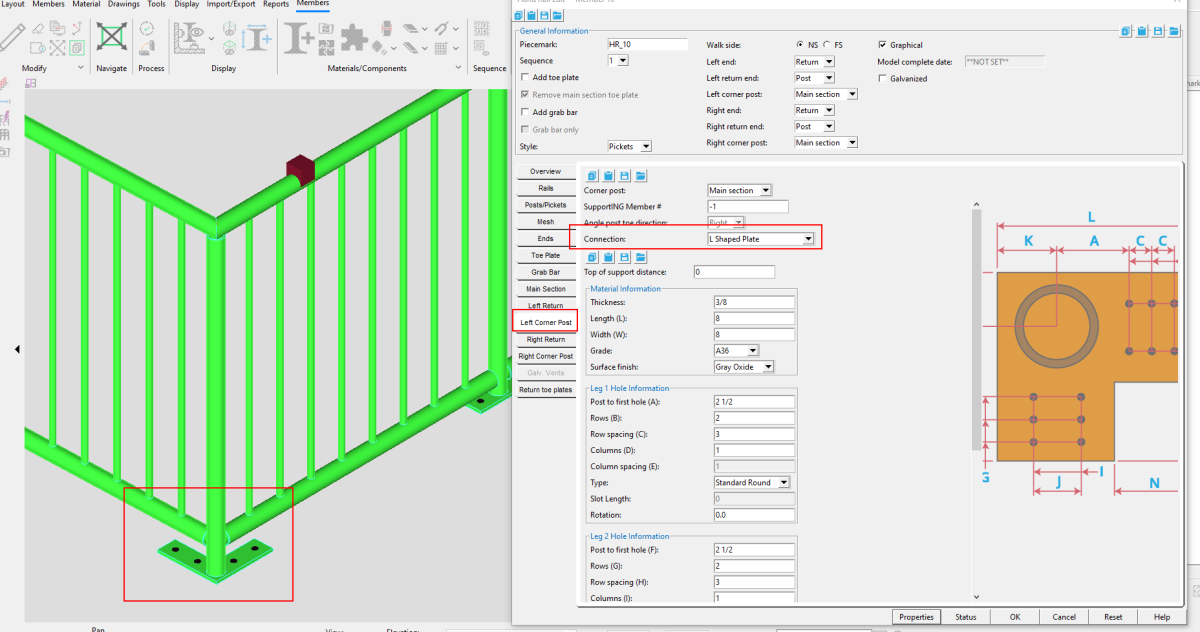
You will also see new tabs in theHand Rail edit window for Left Corner Post and Right Corner post. There you can control a number of settings, including the‘Connection type.’ L-shaped plates are now available to select for corner posts.
PDF Submittal Tool
The PDF Submittal Tool exports sheets and submittal cover sheets to PDF files and, optionally, provides convenient cloud-based hosting for them on Bluebeam Studio.
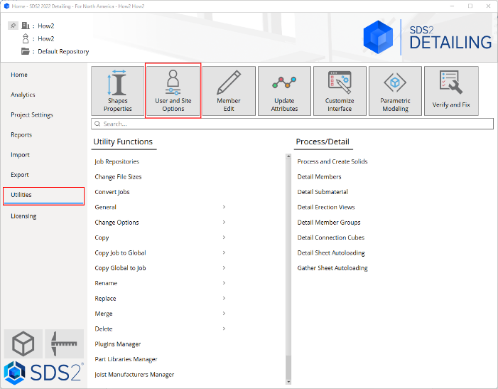
User and Site Options
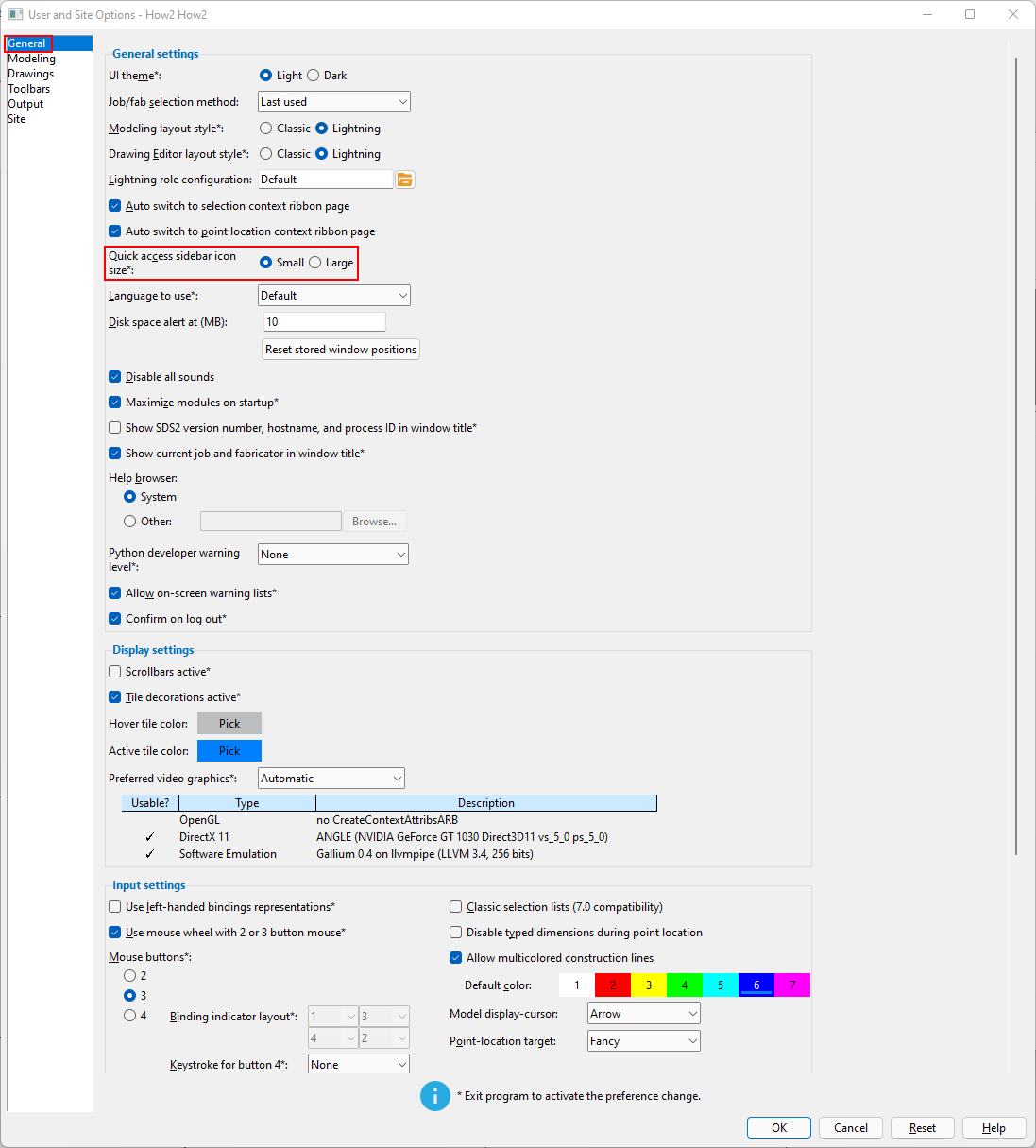
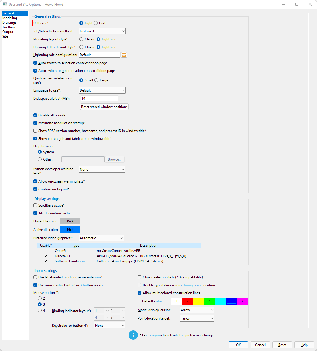
User and Site Options > General > UI theme changes the color scheme of Home, the Modeling and Drawing Editor environments, tool windows, progress bars, etc. The new Dark theme shows light characters and icons on a dark background.
User and Site Options > General > Quick access sidebar items size allows you to change the size of tool icons that appear on the quick access feature of the Lightning layout style.
Connection Cubes
Watch a video tutorial here.
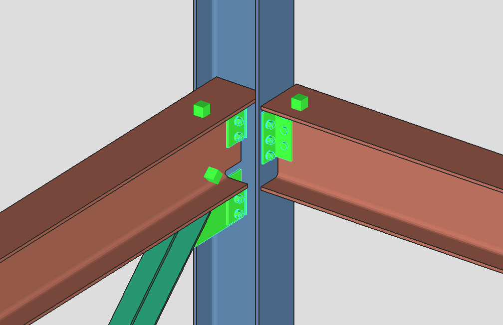
“Connection Cubes” are a new feature in SDS2 2022, designed to aid in communication with project engineers. These advanced PDF reports encompass the entire structural node, rather than only member ends, and include
-
Schedule of minimums
-
2D drawings
-
An embedded U3D
-
Allowable strength summaries
-
Expanded calculations.
You may also add to the report additional notes, a cover sheet, and any other attachments needed.
Selecting a connection cube
To begin creating a connection cube, you will need the Connection Cube Add tool, which you can find through the search bar. It can also be added to a customized ribbon.
Once you select the tool, you will be prompted to select the connection components and/or member ends you would like included in the report.
When your connection cube is selected in the model, a contextual ribbon will appear with additional tools to add and remove components and member ends.
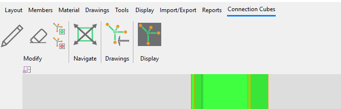
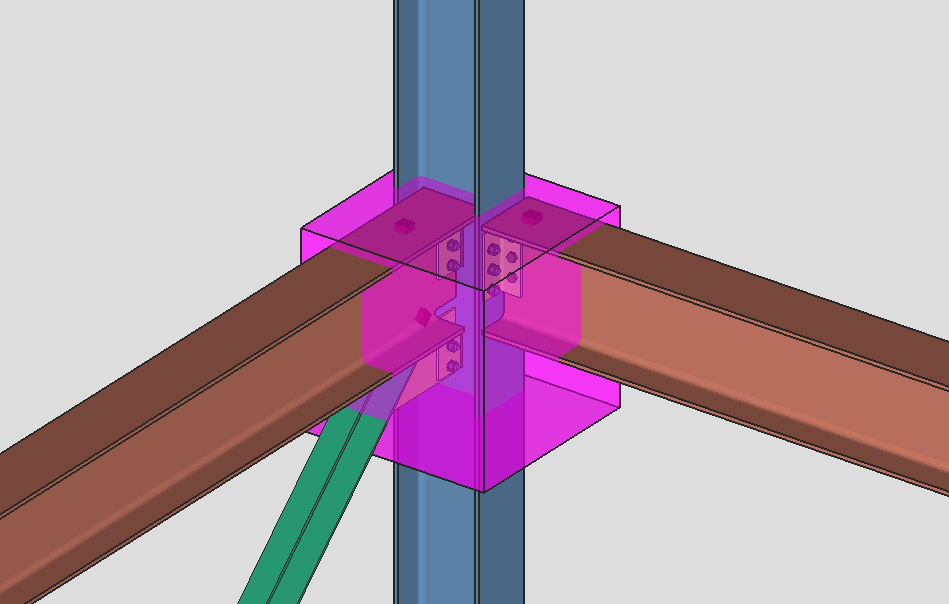
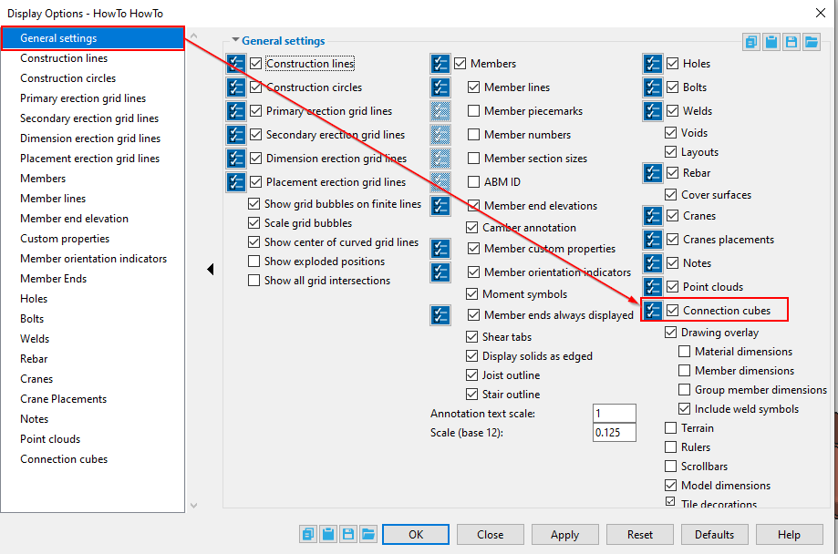
The connection cube visibility can be turned on and off in Display Options .
Preparing the connection cube report
Once you have added a connection cube in the model, you can edit it to setup what will be shown in the report. To edit a connection cube, you can either double click it or select it and then click the “ Edit” button shown in the Connection Cubes contextual ribbon.
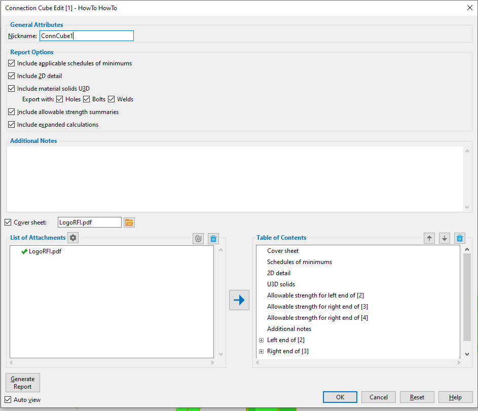
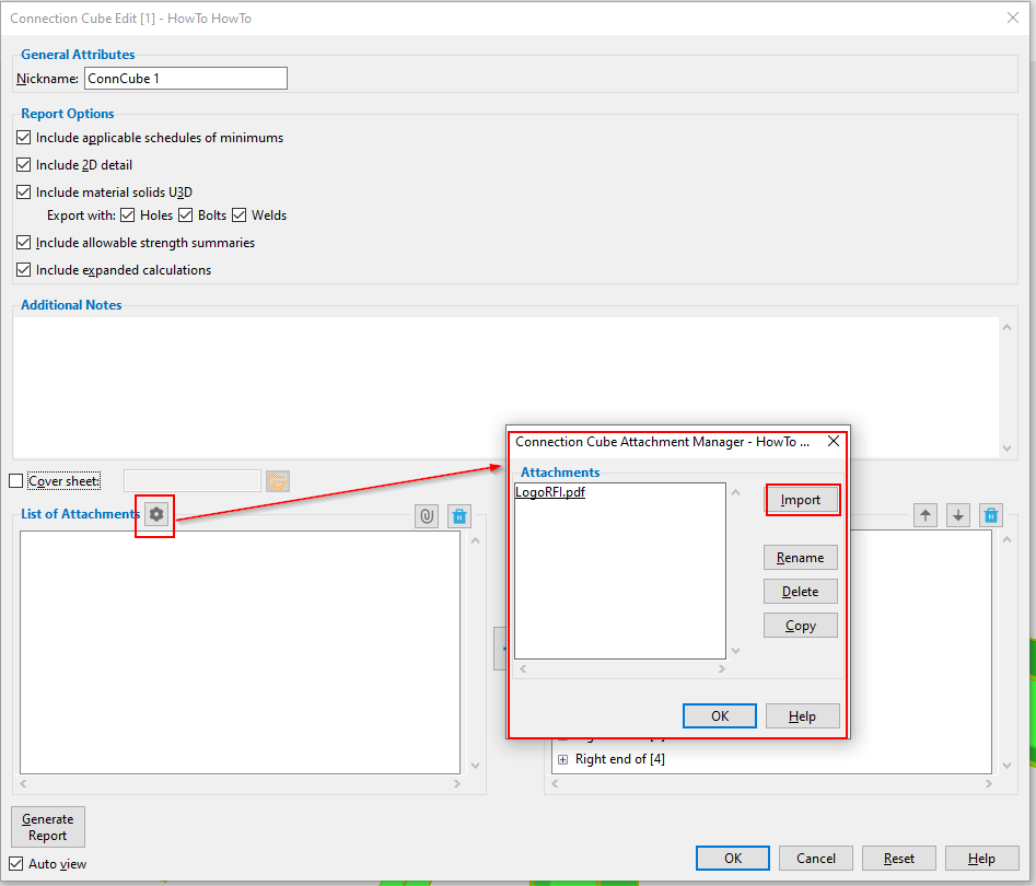
In the Connection Cube Edit window, you will be able to enter a name for your selected cube, select which items you would like included in the report, and add custom items.
Here’s a breakdown of the built-in Report Options.
-
‘Include applicable schedule of minimums.’ This will show the schedule of minimums for structural members and for single plate shear connections, depending on the connections in your cube.
-
‘Include 2D detail.’ This will include a detail drawing of the connection cube. You can add views in the Connection Cube Isolation just as you would for member isolation. You can then detail and cleanup the connection cube the Drawing Editor.
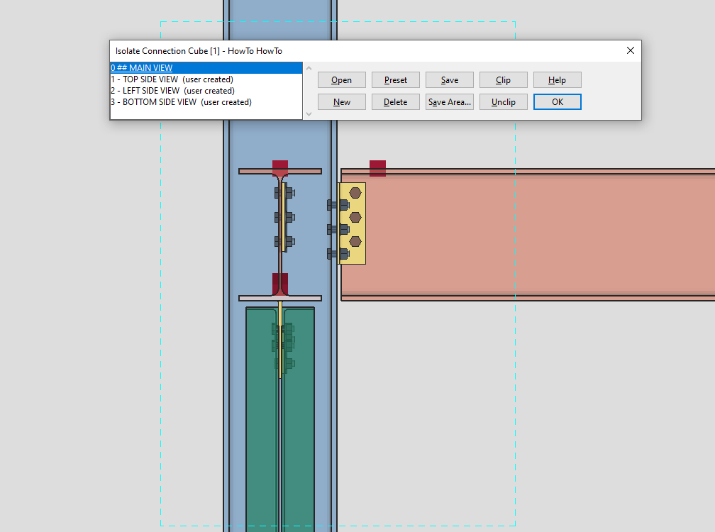
-
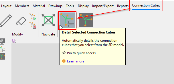
To open the connection cube in the Drawing Editor, select the Detail Selected Connection Cubes tool on the Connection Cubes contextual ribbon, or navigate from the SDS2 Home Screen to Utilities > Detailing Connection Cubes.
-
Upon opening the Drawing Editor, you will see a radio select button for ‘Connection cube details.’
-
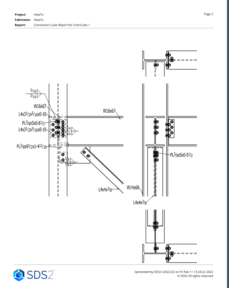
An example of the 2D details shown on a connection cubes report.
-
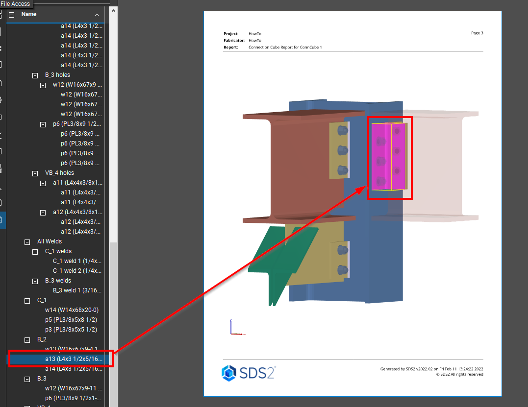
‘Include material solids U3D.’ This will embed an interactive visualization of the connection cube in the PDF report, with options to include bolts, holes, and welds. You can rotate and select materials on the model segment in the PDF report.
-
‘Include allowable strength summaries’
-
‘Include expanded calculations’
Additional Notes
In addition to the default Report Options, you can also type in “Additional Notes,” which will appear after the Design Notes in the PDF report.
Attachments
To add attachments, first click on the “Connection Cube Attachment Manager” button, and then click “ Import” to search for an select PDFs to import into the job. There are options to rename, delete, or copy your selected attachments.
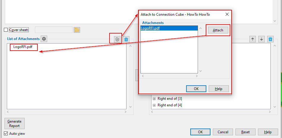
Once a PDF has been added as an attachment, there are several steps you can take. Select the imported PDFs and click “ Attach” to add the files to your ‘List of Attachments’ for the report.
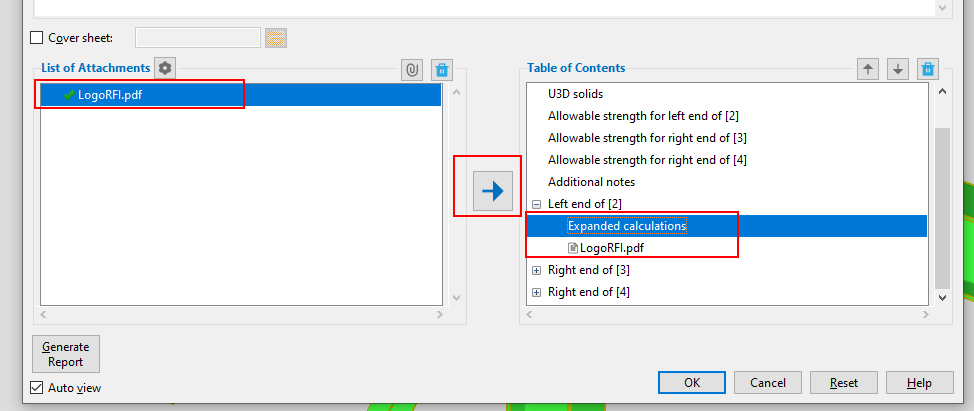
Once a file is shown in the “ List of Attachments,” you can select it and click the blue arrow button to move it into the “Table of Contents” area, which provides a preview of what will be included in the report for the selected connection cube and in what order. A green checkmark will appear in front of the filename in the “List of Attachments” when the file has been added to the “ Table of Contents.”
Attachments will be placed depending on what you have highlighted in the “Table of Contents.” To rearrange items in your “Table of Contents,” and in the corresponding report, select an item and use the up and down arrow buttons. The trash button can be used to delete unwanted items.
 (Image 13)
Attach a cover sheet
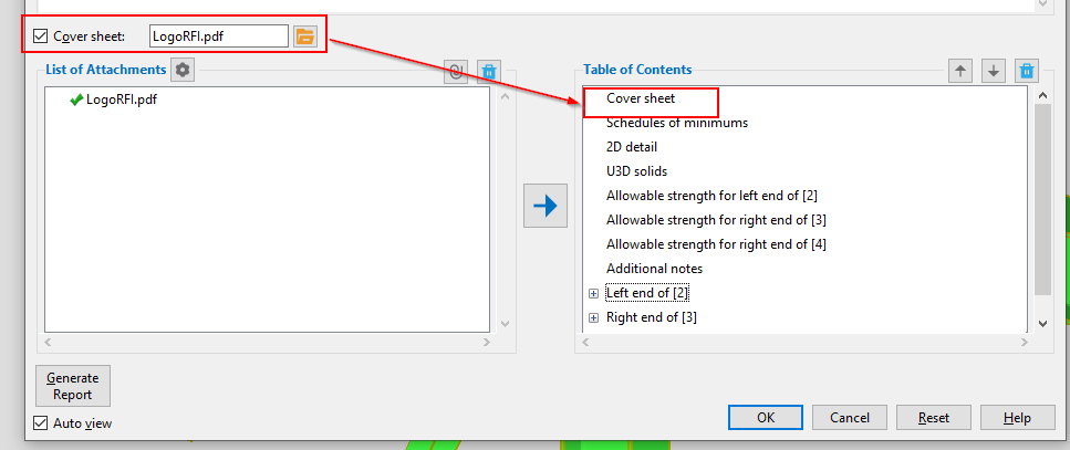
Above the “List of Attachments” is a selection box option to include a custom cover sheet. Select the box, then click on the folder icon to browse and select the PDF attachment that will be used as a cover sheet. Once you select to include the cover sheet, it will automatically be listed at the top of the “ Table of Contents.”
Generate Report
Once your “Table of Contents” is complete, click the “Generate Report” button to compile your PDF report. A standard window will appear with options for saving your file. If the ‘ Auto view’ option is checked, your report will automatically open in your default PDF viewer.
Engineering and Connection Design
Watch a video tutorial here.
SDS2 2022 added new connections and setup options and incorporated unity ratio calculations to better meet the expectations of design engineers.
New Connections
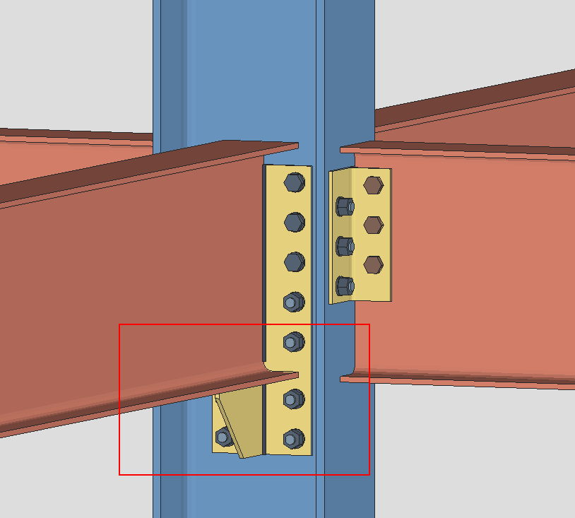
End Plate with Extensions
SDS2 2022 created a new connection that will add a plate extended down if you are using an end plate and the loads are high. When the bolts do not fit within the beam web, this will add an extension plate below the beam, and extend the end plate as well.
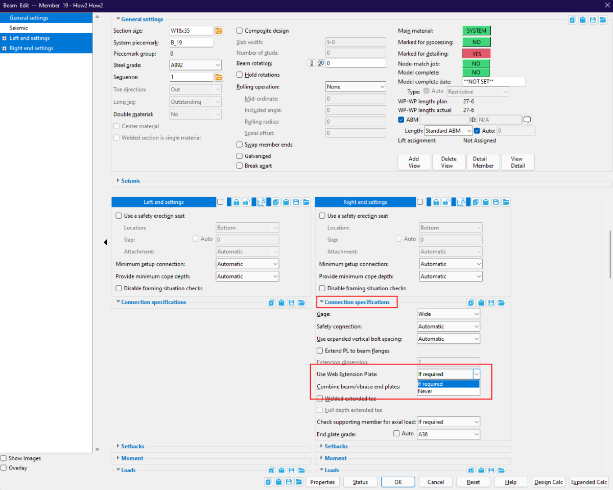
Options to control this connection can be found in the Beam edit window under “Connection specifications.” The option to ‘Use web extension plate’ can be set to either “If required” or “Never.”
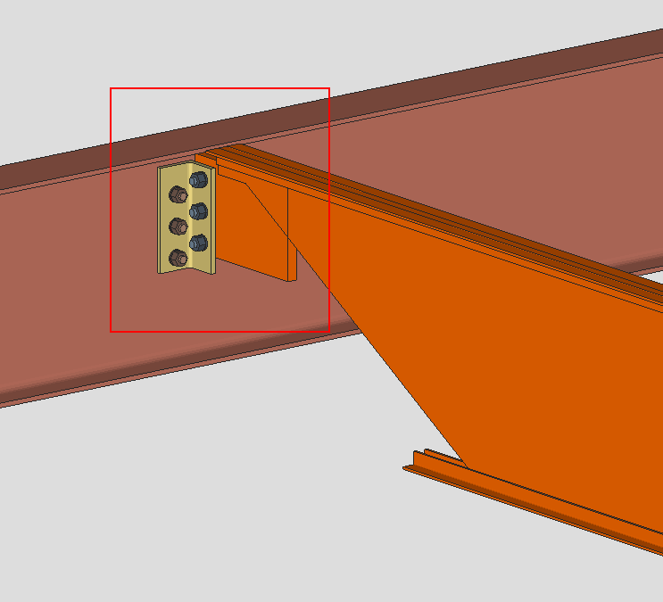
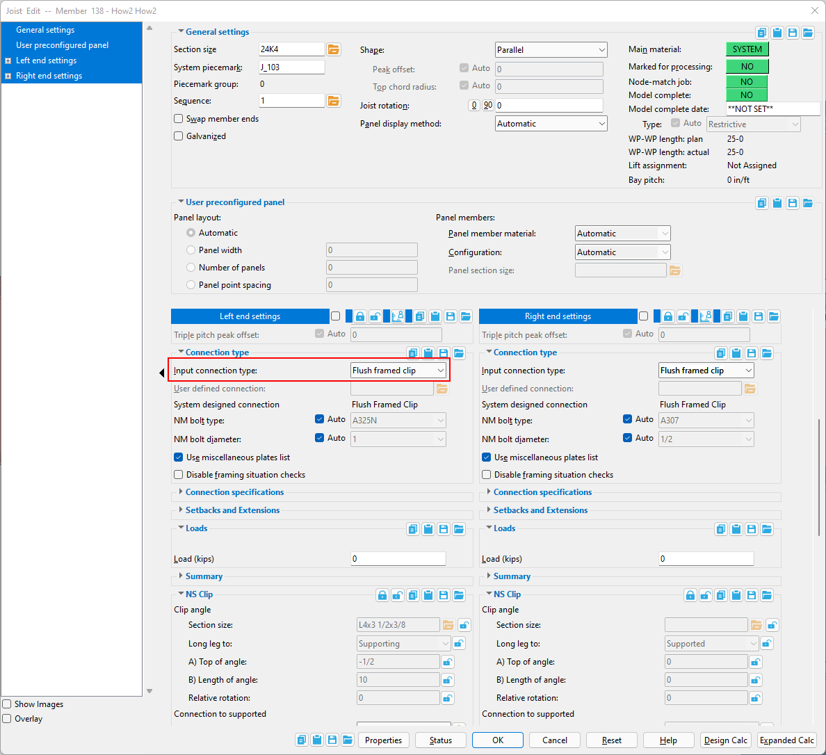
Flush Framed Clip Angle
SDS2 2022 introduced flush framed clip angle connections for Vulcraft joists framed to beams or columns. Although the connection is designed specifically for Vulcraft joists, you can force the connection for other joist manufacturers. To do this, open the member edit screen and set the ‘Input connection type’ to ‘Flush framed clip.’
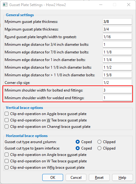
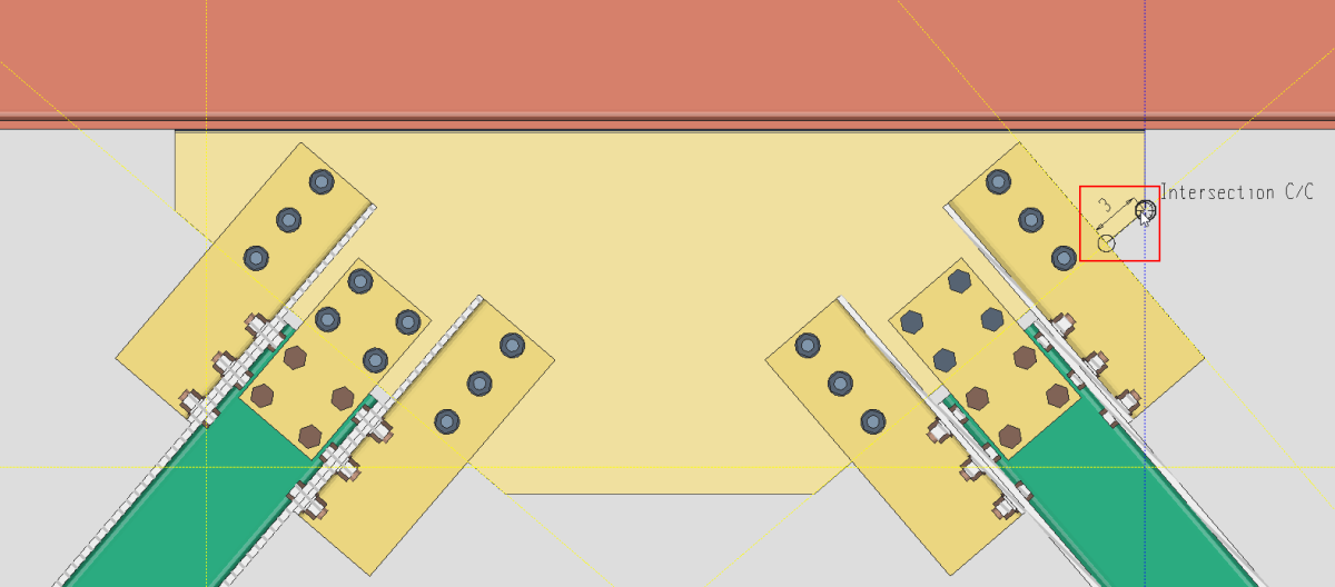
Minimum dimension for Gusset Plates
SDS2 2022 also added a new setup option for gusset plates. This setup option will allow you to specify the shoulder width for both bolted and welded connections.
To edit this dimension in your project settings, go to the SDS2 Home Screen and select Project Settings > Standard Fabricator Connections > Gusset Plate Settings and enter the desired values under the ‘General settings’ section.
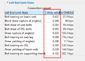
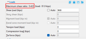
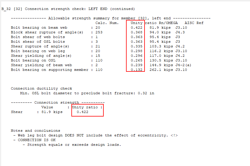
Unity Ratios
SDS2 2022 incorporated unity ratio calculations to the member edit windows for the limit states and when placing a user load.
With the unity ratio it is easier to visualize the amount of excess capacity in the connection. For example, if the maximum unity ratio is 0.95, then there is an additional 5% of capacity available. Unity ratio is commonly used by engineers and engineering software and will be valuable when it comes to reviewing design calculations.
Saving Material Fit Operations
Watch a video tutorial here.
In SDS2 2022, material operations that are made using fit exact, fit notch, or fit cope will be saved as an object that can be seen, edited, and deleted on the material. This means that when a change is made and the material is regenerated, the material operations will remain on the material. In previous versions these operations would have been lost.
Note: For SDS2 2022, this function only works for fit exact, fit notch, and fit cope. Other material operations will be lost upon regeneration.
If material that was fit to changes, the fitted material will not update as there is no connection between the material that was fit and the material it was fit to, only a snapshot that was created when the fit was done.
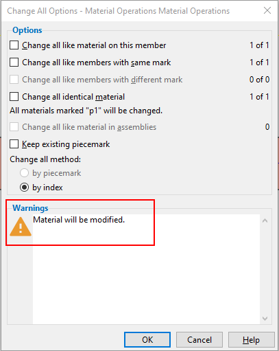
The material operations are automatically saved. After applying the fit, the Change All Options – Material Operations window will appear with a warning that “Material will be modified.”
Modifying Material Operations
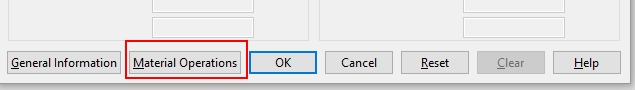
The material operations can be accessed from the >Material Edit window by clicking the “Material Operations” button.
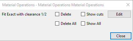
The Material Operations window will allow you to edit, show, or delete the selected material operation.
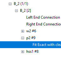
Material operations can also be accessed from the model tree. Selecting the material operation in the model tree will highlight it in the model.
Tools
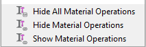
There are new tools to assist in modifying the material operations. These include: Hide All Material Operations, Hide Material Operations, andShow Material Operations.
User Experience Updates
Watch the video tutorial about new features.
Icons in the program have a new look. See the SDS2 2021 & Above Icon Guide.
New features in the SDS2 2022 interface have been added to improve the user experience. Most notable includes a dark mode option, as well as an enhanced search tool and new options for your quick access toolbar.
Dark mode
The dark mode option will allow you to change the theme of SDS2 into a dark theme. This will change the interface for all windows inside of SDS2, including the Home Screen, modeling, and drawing interfaces. Dark mode has been shown to reduce eye strain for users, and to reduce the computer’s power consumption.
SDS2 2022 will be set to light mode by default. To switch to dark mode, go to Home Screen > Utilities > User and Site Options. In the User and Site Options window, there are two settings that need to be switched to activate dark mode.
-
Under “ General” settings, find the ‘UI theme’ option and select the radio button for ‘ Dark.’
-
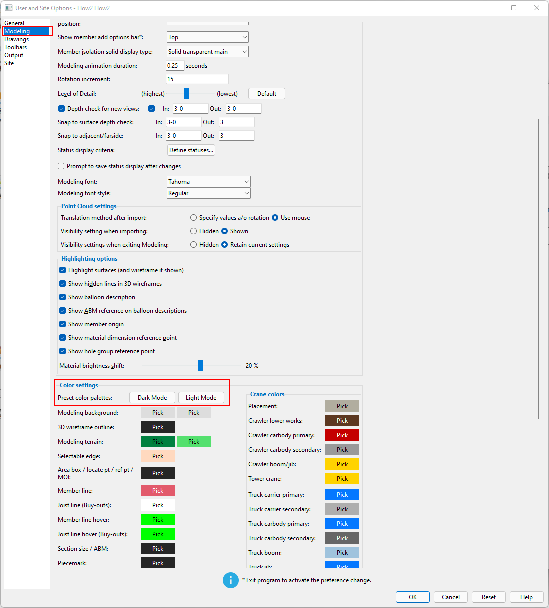
Under “ Modeling” settings, find the “Color Settings” section and click the button for “ Dark Mode” for the ‘Preset color palettes’ setting.
Search to locate tools
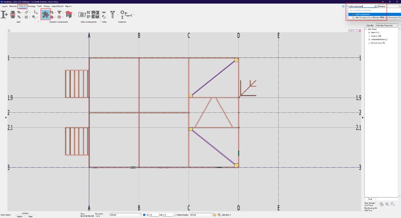
To help users learn their way around the SDS2 interface, we have added functionality to our search tool. When you type the name of a tool or command into the search bar, the selected tool will be revealed and highlighted (if available) in the ribbon.
The example below shows a search for the “Add Component” tool. When selected from the search results, SDS2 will open the Material ribbon and highlight the tool.
Quick access pinned icons
In SDS2 2022 we have added two new features to our quick access pinned icons. Now you’ll be able to rearrange your icons and select the size you want them to display.
To move an icon on the toolbar, simply right click and hold the icon you wish to move, then drag it to the desired position.
To change the size of the icons, go to the SDS2 Home Screen and navigate to Utilities > User and Site Options. Inside the ‘General’ tab, you will find the option to toggle the “Quick access sidebar icon size” between small and large.