 Toolbar Configuration ( Modeling & Drawing Editor ) (' Classic ' only)
Also see :
- Items on toolbars (topic)
- User and Site Options > Toolbars > Drawing Editor (default configuration file loaded at startup)
- User and Site Options > Toolbars > Modeling (default configuration file loaded at startup)
- Load Configuration (to load a configuration other than the default)
- Delete Toolbar Configuration (utility)
page 1 | contents | options > toolbar configuration (classic)
 What is a toolbar?
Toolbars are graphical features of the user interfaces in Modeling and the Drawing Editor . You can place icons or decorations onto toolbars as described in step 3 .

|
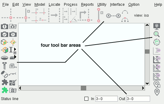
| The four fixed toolbars in Modeling . If the box is not checked for User and Site Options > General > " Maximize modules on startup ," then the icons and decorations placed onto these toolbars set the size of the graphics window that these toolbars surround. |

|
The floating toolbar. If you remove all icons from the floating toolbar, the floating toolbar will not appear when the configuration is Loaded . |
page 1 | contents | options > toolbar configuration (classic) | top
![]() Command groups :
Command groups :
| Erection View Detailing : File | View - Tiles | Navigate | Navigate - Navigation Mode | Navigate - Surface Mode | Settings | User Modes | Selection | Solids | |
| Assembly Editor : File | Edit | View | View -- Solids Mode | View - Tiles | Navigate | Navigate - Navigation Mode | Navigate - Surface Mode | Model | Model - Construction Lines | Model - Construction Circles | Model - Member | Model - Material | Model - Hole | Model - Bolt | Model - Weld | Locate | Settings | User Modes | Selection | |
page 1 | contents | options > toolbar configuration (classic) | top
![]() Step-by-step instructions :
Step-by-step instructions :
1 . Before configuring a toolbar:
1a : Confirm that User and Site Options > " Modeling layout style " or " Drawing Editor layout style " is set to ' Classic '.
1b : Confirm that the correct configuration file is currently loaded. The default configuration is the choice selected for User and Site Options > Toolbars > " Modeling " or " Drawing Editor ." To load a configuration file other than the default file that is automatically loaded when Modeling or Drawing Editor launches, choose Settings > Load Configuration .
2 . In Modeling or Drawing Editor , invoke Toolbar Configuration using any one (1) of the following methods:
Method 1 : Choose Settings > Toolbar Configuration .
Method 2 : Click the Toolbar Configuration icon, which is pictured above. If the icon is not currently on your toolbar, you can add it using Toolbar Configuration .
Method 3 : Use a keyboard shortcut .
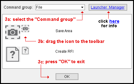
3 . A list of available icons appears in the area surrounded by your currently loaded toolbars. Note that you can also create or manage icons for launching parametrics or advanced selection scripts or report writer reports by pressing the " Launcher manager " button.

3a : Select the " Command group " that you want (for instance, select ' View Commands '). As you change the command group, the icons or decorations within that group are displayed on the selection list. If more icons exist than can be shown on the list at one time, use the scroll bars to scroll down the list, thus causing additional icons to be shown.
3b : Drag the icon or decoration onto the toolbar where you want it located. Dragging is done with the left mouse button. When you release the left mouse button, the icon is placed on the toolbar at the position of your mouse pointer (
). To remove an icon from a toolbar, drag it off the toolbar.
3c : Repeat steps 3a and 3b as many times as you like. When you are done making changes to your toolbars, press the " OK " button at the bottom of the window.
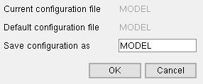
4 . After you press " OK ," the Save Configuration File dialog opens.

|
" Default configuration file " is the file selected for the appropriate edition under User and Site Options > Toolbars . |
Alternative 1 : Enter a file name to " Save configuration as " (the currently loaded file is shown by default), then press " OK " to save your changes under that file name. Unless you entered an entirely new configuration file name, another ok-cancel dialog opens -- press " OK " to overwrite the old file.
Alternative 2 : Press " Cancel " to have your changes saved in RAM only. During your current session of Modeling or the Drawing Editor , the toolbar will be configured as you have specified. However, when you exit the Modeling or Drawing Editor program and restart, your changes will be forgotten and the toolbar will be configured as it was before step 2.
page 1 | contents | options > toolbar configuration (classic) | top


