"  Web Doublers " connection design locks
| Web doublers for 2-point vertical braces to a wide flange beam or column are designed per choices made to " |
- " Plate length " is measured parallel with the length of the shared gusset plate.
- " Check supporting for web shear " = ' If required ' can get web doublers for non-seismic 2-point bracing.
|
||||
"  |
|
|||
|
||||
User Defined Connections: Settings that are locked (
) in a user defined connection file will automatically be locked on a member edit window for which that file is the " Input connection type ." You can, if you so choose, manually lock additional settings on the member edit window, and your changes will be retained, through multiple processes, so long as you do not change to a different connection then switch back to the original user defined connection.
Vertical Brace Edit: To change a setting, first set it to locked (
). Related settings that are unlocked (
) may be updated, and the "
Left/Right end limit state " calculations will be updated. Settings that are locked (
) will not be changed by connection design , even if doing so might prevent a connection failure.
Connection design locks :
| Locks not dimensioned or called out on the drawing are marked ( not depicted ). |
![]() Web Doublers
Web Doublers
Plate location ( not depicted ): ' Neither side ' or ' Near side ' or ' Far side ' or ' Both sides '.
' Neither side ' causes no web doubler plate to be designed. If a 2-point " Seismic brace " has been designed without web doubler plates, then ' Neither side ' is the choice that is made in the "
Web Doublers " leaf. Switching this option to, for example, ' Both sides ' will result in the other unlocked options in this leaf being populated with values that will generate web doublers.
' Near side ' designates that a doubler plate be designed on the near side web of the supporting member (beam or column).
' Far side ' designates that a doubler plate be designed on the far side web of the supporting member.
' Both sides ' designates that a doubler plate be designed on both sides of the web of the supporting member.
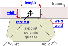
Refx, center of doubler ( refx=0 ): A positive or negative distance .
' 0 ' is the unlocked (
) distance that is entered by default. It places the web doubler half way between the two braces.
A positive distance moves the center of the doubler toward the right end of the supporting member (beam or column).
A negative distance moves the center of the doubler toward the left end of the supporting member.
Plate length ( length ): The distance that each doubler plate extends parallel with the length of the supporting member.
Plate width ( width ): The distance that each doubler plate extends parallel with the depth of the supporting member.
Plate thickness ( not depicted ): The rectangular plate " Material thickness " of the web doubler or, if there are NS and FS web doublers, of each of the two web doublers.
Weld size ( weld ): The weld size for shop welding the four edges of each web doubler to the beam or column web.


