- To open this window .
- If you are editing one vertical brace, its member number (" Member xx ") is shown in the title bar, and the "
 Summary " lists other braces with the same piecemark.
- Vertical Brace Edit - Multiple Members is this window's title if you are editing multiple vertical braces .
- This window is titled Vertical Brace Review and is mostly read-only if the " Model complete date " is set and ' Restrictive ' is selected for any vertical brace being edited.
-
 " Copy " " Paste " " Save " " Load " buttons (form buttons) are embedded in the headers for individual leaves on this window. They apply to the settings that are contained in that leaf. Some form buttons, such as those for [ Left end settings ] apply to multiple leaves in that section. Click here (
  ) for more information. " Paste " and " Load " replace mixed entries to a single field with a single entry. " Copy " and " Save " ignore fields with mixed entries, treating them as if they have no entry or do not exist. Form buttons above sections that have multiple subordinate leaves under them -- e.g., [ Left end settings ] or [ Right end settings ] -- operate on settings under all of the subordinate leaves. For example, if you wanted to copy a connection from the left end to the right end, you would use the " Copy " button under [ Left end settings ] then use the " Paste " button under [ Right end settings ]. Special cases: Form buttons do not operate on " Piecemark " and " End elevation ." Tip : Right-click a " Load " button to get a list of recently created forms that can be applied to the section which that " Load " button governs. Selecting the name of a form from the list populates the fields in that section with the form settings that were saved under that name.
- " Save " (
 ) places a file (which you name) in a subfolder of the
  form/vert-brace folder that is used by your current version of this program -- the exact subfolder depends on where the button is located. " Load " (
  ) takes you to that same folder.
 General settings General settings |
|
|
|
|
|
Section size: The brace's main material (e.g., ' L4x4x1/2 ') from the local shape file .
To enter a section size: You can type in the section size that you want, or you can press the "file cabinet" browse button (  ) and double-click any section that is on the list of available materials in the local shape file . Also, if you enter a section size that is not available , validation brings up a yes-no dialog with the warning, " The section size is not available from suppliers. Are you sure you want to use it? "
 C15x50 C15x50
C15x40
C15x30
C12x30
C12x25
C12x20.7
|
 |
|
|
|
|
|
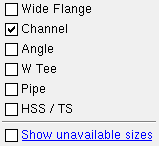
A selection dialog like this one opens when you press the button. In this example, only "  Channel " is checked, and therefore only channel sections are listed. Channel " is checked, and therefore only channel sections are listed.
|
Invalid material types: If you enter a " Section size " that is not one of the "Valid Material Types for Vertical Braces," you will get the following end connection failure message :
| Invalid material type for this member
|
Round bar material may be entered as the vertical brace " Section size " if you want connection design to design rod bracing . Pressing the button lets you access the list of round bar section sizes that are available in the local shape file . Click here for more information from the Connection Guide.
Note: Vertical brace member worklines (stick form lines) are drawn through the neutral axes of W , S or welded plate W , HSS round , round bar or HSS rectangular braces. For a W tee or S tee vertical brace, the workline is drawn through the top flange center line if the " General settings " > " Stem orientation " is ' Horizontal ' or along the connection bolt line if the " Stem orientation " is ' Vertical '. For a single angle vertical brace, the workline is drawn along the leg to gusset per " General settings " > " Locate on neutral axis ." For a channel vertical brace, the workline is at the half-depth of the heel of the channel (the channel web is vertical).
To add/edit section sizes: Shapes Properties .
Required file for editing: The " Shape file " path must be set to the local shape file (press " Local ").
To copy section sizes from another shape file: Copy Shapes .
Status Display: Member status > Member section size
Report Writer: Member.MaterialFile.SectionSize
Advanced Selection: m.SectionSize
Parametric module: m.SectionSize
Piecemark or System piecemark or User piecemark or Frozen piecemark :
Piecemark group :
Steel grade :
Surface Finish:
Sequence :
Note this scenario: You are editing one brace, which shares its piecemark with other vertical braces. You change its sequence and other settings. If you press " Yes " when prompted " Do you want to change all... ," the changed sequence applies only to one brace you are editing, but the other settings are applied to all braces with the same piecemark.
Swap member ends :
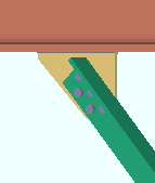
One gage line: or  . This " General settings " option applies when the vertical brace's " Section size " is an angle.
|
If this box is checked ( ), connection design creates a single column of bolts to connect the angle to the gusset. This may result in a gusset plate that is larger or thicker.
|
|
If the box is not checked ( ), connection design creates two columns of bolts to connect the angle to the gusset when the length of the angle leg to the gusset is greater than 5 inches (127 mm).
|
Report Writer: Member.Settings.OneGageLineofBoltsOnBrace
Advanced Selection: m.OneGageLineOfBoltsOnBrace
Parametric module: m.OneGageLineOfBoltsOnBrace
Stagger bolts: or . This " General settings " option applies when the vertical brace's " Section size " is an angle and the leg to gusset is 5 inches (127 mm) or longer.
|
If this box is checked ( ), connection design staggers the bolts that connect the angle to the gusset. Row spacing may be increased (for example, from 3 inches to 3 1/2 inches) to keep bolts on different gage lines farther apart than 2 2/3 times the bolt diameter.
|
|
If the box is not checked ( ), connection design connects the angle brace to the gusset with two columns of non-staggered bolts, resulting in an extra bolt being used and causing the gusset plate to be larger than it would be otherwise.
|
Report Writer: Member.Settings.StaggerBoltsAtAngleBraceConnections
Advanced Selection: m.StaggerBoltsAtAngleBraceConnections
Parametric module: m.StaggerBoltsAtAngleBraceConnections
Welded section is single material: or . This " General settings " option applies when the vertical brace's " Section size " is a welded plate wide flange .
|
... single material |
|
|
|
... single material |
|
|
|
|
If this box is checked ( ) when you detail the brace, the member bill of material will list the welded plate wide flange as a single section size. You can generate a separate submaterial detail for the section (but not for the plates that make up the section). On a member such as a miscellaneous member, which does not have the " Welded section is single material " option, welded plate sections are always treated as single material.
If the box is not checked ( ) when you detail the brace, the member bill of material will list the welded plate wide flange section as three plates. You can generate separate submaterial details for the plates.
CNC for DSTV: Download plates (too) of welded sections
Report Writer: Member.Settings.WeldedSectionIsSingleMaterial
Break Apart : or .
Stem orientation: Horizontal or Vertical . This " General settings " option applies when the vertical brace's " Section size " is a W tee or S tee section.
|
' Horizontal ' bolts the flange of the tee directly to the gusset plate. The top flange center line of the tee aligns with the work line of the brace.
|
|
' Vertical ' aligns the forward edge of the tee with the gusset and connects the gusset and brace with a bolted connection plate. The bottom bolt line aligns with the workline of the brace if the stem is ' Up ' (as shown). The top bolt line aligns with the workline if the stem is ' Down '. Two choices are available for the " Connection type " (' Web plates ' or ' Coped flange ').
|
Connection type: Web plates or Coped flange . This " General settings " option applies to a W tee or S tee vertical brace whose " Stem orientation " is ' Vertical '.
| VIDEO
|

|
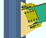
A stem-vertical W tee vertical brace has its " Connection type " set to ' Coped flange ' and its " Side of gusset " set to ' Near side ' then to ' Far side '.
|
|
' Web plates ' uses NS and FS web plates to field bolt the brace to the gusset. The web plates shop bolt to the brace. Web or gusset fill plates are provided as needed.
' Coped flange ' cuts the stem-vertical tee's NS or FS flange with a " Cut flange flush " top/bottom flange operation and field bolts the stem of the tee to the gusset plate. You can specify the " Side of gusset " (' Near side ' or ' Far side ').
Connection Guide: Click here and here for W tee examples. Click here for a wide flange example.
Long leg: Outstanding or To gusset . This " General settings " option applies when the vertical brace's " Section size " is an angle with unequal legs.
|
' Outstanding ' bolts the short leg of the angle brace to the gusset plate, with the long leg outstanding.
|
|
' To gusset ' bolts the long leg of the angle vertical brace to the gusset plate.
|
Advanced Selection: m.LongLegOfAngleIsVertical
Parametric module: m.LongLegOfAngleIsVertical
Angle leg turned up: or . This " General settings " option applies when the vertical brace's " Section size " is an angle. Connection design can create a ' Vbrc plate ' for a leg-up single- or double-angle brace in the same framing conditions that it can for a leg-down angle brace. It can also design a ' Welded ' connection on a leg-up double-angle vertical brace (' Back to back ') to the stem of a W tee (or S tee) chord member.
|
If this box is checked ( ), the leg of the points angle up. The angle is oriented so that the leg that bolts to the gusset plate is above the outstanding leg.
|
|
If the box is not checked ( ), the leg of the angle points down. The angle is oriented so that its outstanding leg is above the leg that bolts to the gusset plate.
|
Examples from the Connection Guide: Click here and here and here and here .
Report Writer: Member.Settings.AngleLegTurnedUp
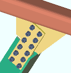
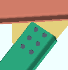
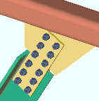
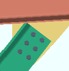
Double material: or . This " General settings " option applies when the vertical brace's " Section size " is an angle or channel.
If this box is checked ( ), the vertical brace main material is double material. For a double-angle brace, you have the choice of a ' Back-to-back ' or ' Star ' configuration.
If the box is not checked ( ), the vertical brace is a single angle or channel.
Report Writer: Member.Settings.DoubleMaterial
Advanced Selection: m.DoubleMaterial
Parametric module: m.DoubleMaterial
Configuration: Back to back or Star or Near side or Far side . This " General settings " option applies when the vertical brace's " Section size " is an angle and the box is checked for " Double material ."
| VIDEO
|
|
The " Configuration " for each of three double-angle vertical braces that cross at an intersection plate is set to ' Near side '.
|
|
|
' Back to back '
|

|
|
|
' Star '
|
|
|
|
' Near side '
|
|
|
|
' Far side '
|
|
|
If ' Back to back ' is selected, the two angles are laid out back-to-back with a spacer (stitch plate) in between. This example shows a bolted ring or bolted plate spacer.
If ' Star ' is selected, the two angles are laid out in a star configuration using vertical spacers (stitch plates). A bolted spacer is used in this example.
' Near side ' places the angles back-to-back on the near side of the gusset plate. No stitch plate is required. The gusset plate, not a stitch plate, is shown in the above example.
' Far side ' places the angles back-to-back on the far side of the gusset plate. No stitch plate is required. The gusset plate, not a stitch plate, is shown in the above example.
Stitch plates are required for ' Back to back ' and ' Star ' configurations. The " Type of spacer " is specified in Home > Project Settings > Fabricator > Member Detailing and Fabricator Options > the " Stitch Plates " section. The " Stitch plate gap " and " Maximum stitch plate spacing " and " Number of stitch plates " can be set on this window.
Advanced Selection: m.Configuration
Parametric module: m.Configuration
Side of gusset: Center or Near side or Far side . This " General settings " option applies to W tee (or S tee ) or angle or channel or wide flange vertical braces. A stem-horizontal W tee or S tee brace will attach to the gusset much like an angle brace. A stem-vertical W tee or S tee brace must have its " Connection type " set to ' Coped flange ' in order for you to be able to set the " Side of gusset ." A wide flange vertical brace must have its " Web orientation " set to ' Vertical ' in order for you to be able to set the " Side of gusset ."
| VIDEO
|
|
A stem-vertical W tee vertical brace has its " Connection type " set to ' Coped flange ' and its " Side of gusset " set to ' Near side ' then to ' Far side '.
|
|
| VIDEO
|
|
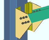
A wide flange vertical brace produces the failure message, " WF brace flg is too narrow for connection ." This is fixed by switching the " Side of gusset " from ' Center ' to ' Near side ' or ' Far side ', thus instructing connection design to field bolt the web of the wide flange directly to the gusset.
|
|
' Center ' may be applied when the " Section size " is a wide flange. If the brace was previously set to ' Near side ' or ' Far side ', this removes the previously applied connections (each end). The " Connection arrangement " that is set under left- and right-end " Connection specifications " will be the newly applied end connections.
' Near side ' bolts the brace to the near side of the gusset plate. The outstanding leg of an angle (toes of the channel, stem of a stem-horizontal W tee) point toward you when you are facing the near side of the gusset plate. For a web-vertical wide flange or a stem-vertical W tee, this performs " Cut flange flush " operations on the top and bottom far side flanges of the brace.
' Far side ' bolts the brace to the far side of the gusset plate. The outstanding leg of the angle (toes of the channel, stem of a stem-horizontal W tee) point away from you when you are facing the near side of the gusset plate. For a wide flange or stem-vertical W tee, this performs " Cut flange flush " operation on the top and bottom near side flanges of the brace.
Stem direction: Up or Down . This " General settings " option applies to W tee vertical braces whose " Stem orientation " is ' Vertical '. The " Connection type " for such a brace can be ' Web plates ' or ' Coped flange '.
|
' Up '
|
|
web plates
|
coped flange
|
|
|
|
|
' Down '
|
|
web plates
|
coped flange
|
|
|
|
' Up ' points the stem (web) up on the W tee brace. The bottom bolt line of the connection aligns with the work line of the brace.
' Down ' points the stem (web) down on the W tee brace. The top bolt line of the connection aligns with the work line of the brace.
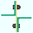
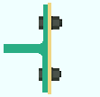
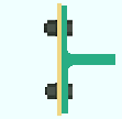
Web orientation: Vertical or Horizontal . This " General settings " option applies when the vertical brace's " Section size " is a wide flange or S shape or welded plate wide flange.
|
' Vertical '
|
|
|
|
' Horizontal '
|
|
|
' Vertical ' makes the web of the brace vertical to the world. If the " Connection arrangement " is set to ' Standard ', you will get a connection like that shown above.
' Horizontal ' makes the web of the brace horizontal to the world. If the " Connection arrangement " is set to ' Flange gussets ', you will get a connection like that shown above.
Note: If this brace shares a gusset with another wide flange brace, both braces need to have the same web orientation.
Long side: Vertical or Horizontal . This " General settings " option applies when the vertical brace's " Section size " is an HSS rectangular or tube section.
|
' Vertical '
|

|
|
|
' Horizontal '
|

|
|
' Vertical ' makes the long side of the tube vertical.
' Horizontal ' makes the long side of the tube horizontal.
Status Display: Member status > HSS long side orientation
Advanced Selection: m.LongSide
Parametric module: m.LongSide
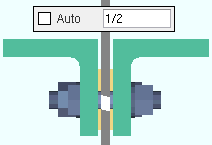
Minimum gusset thickness: Auto or a user-entered thickness (in the primary dimension " Units " or other units ).
' Auto (checked) ' instructs connection design to apply the Home > Project Settings > Fabricator > Standard Fabricator Connections > Gusset Plate Settings > " Minimum gusset plate thickness "
' Auto (checked) ' lets you can type in a minimum thickness. Connection design will create a gusset plate that is as thick or thicker than the thickness that is entered.
Tip: If a Search for Braces with Different Thickness Gussets shows that connection design has created gussets with different thicknesses and you want to make them the same, you can set the " Minimum gusset thickness " on this brace to the thicker of two gussets. As a result, both gussets will be the same thickness.
Report Writer: Member.Settings.UserInputMinGussetThickness
Advanced Selection: m.UserInputMinGussetThick
Parametric module: m.UserInputMinGussetThick
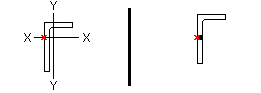
Locate on neutral axis: Automatic or Yes or No . This " General settings " applies when the vertical brace's " Section size " is an angle . Regardless of the selection made here, the member line of the vertical brace runs along the surface of the angle leg that attaches to the gusset.
workline ( x )
on neutral axis
|
workline ( x )
on gage line
|
 |
' Automatic ' instructs connection design to align the vertical brace angle material per Home > Project Settings > Fabricator > Member Detailing & Fabrication Options > the " Vertical Braces " section > " Locate angle braces on neutral axis ."
' Yes ' causes the angle material's X-X axis or Y-Y axis (shown in the AISC Structural Shapes tables) to intersect with the member line of the brace.
' No ' aligns the gage line of the angle material with the member line of the brace. An angle's gage line is the " Long leg gage " or " Short leg gage " entered in the local shape file .
Note: The member line of the brace is not affected by the choice you make here. This option orients the brace material with respect to that member line.
End connection failure message: Both braces must be either on/off the neutral axis
Report Writer: Member.Settings.PlaceAngleBracesOnNeutralAxisDescription
Advanced Selection: m.PlaceAngleBracesOnNeutralAxisDescription
Parametric module: m.PlaceAngleBracesOnNeutralAxisDescription
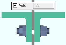
Stitch plate gap: Auto or a user-entered distance . This " General settings " option sets the gap between " Double material " angle or channel vertical braces and also sets the thickness of the stitch plate ( spacer ).
|
If the box for " Auto " is checked ( ), connection design applies a gap that is the thickness of the gusset.
|
|
If the box for " Auto " is not checked ( ), then the distance that is entered here (in the primary dimension " Units " or other units ) sets the gap that separates the two angles or channels that make up the double-material brace.
|
Setup: Home > Project Settings > Fabricator > Standard Fabricator Connections > Plates > the " Other plates " section > " Stitch plate material grade "
Report Writer: Member.StitchPlateGap
Report Writer: Member.Settings.AutoGapForDoubleBracesDescription
Max stitch plate spacing: Auto or a user-entered distance . This " General settings " option sets the distance (center-to-center) between stitch plates and the left/right end of the vertical brace. Left/right end = end of the brace material for a ' Plain end ' or ' Welded ' connection. Left/right end = inside bolt if the end has a gusset. The actual spacing may be less than the spacing entered here, unless exact or variable spacing is entered as described in the table below.
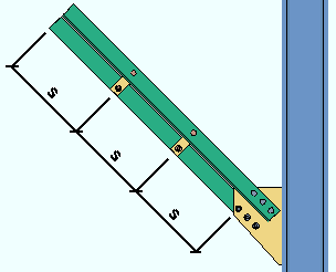
|
s = spacing
|
|
Exact or Variable Spacing
|
|
1-0,2-0,2-6
|
3 stitch plates, the first 1-0 from the left end, the second 2-0 from the first.
|
|
0,2-0,2-6
|
2 stitch plates, the first 2-6 from the right end.
|
|
1-0,0,3,0,2-0
|
1 stitch plate 1-0 from the left end, another 2-0 from the right end, and 3 in between at automatically calculated equal spacing.
|
If the box for " Auto " is checked ( ) and a number is entered to " Number of stitch plates ," that number of equally spaced stitch plates are generated. If " Auto " is checked both here and for the " Number of stitch plates ," setup choices are applied from Home > Project Settings > Fabricator > Detailing > Member Detailing Settings > the " Stitch Plates " section.
If the box for " Auto " is not checked ( ), then " Auto " must be checked for " Number of stitch plates " if you want to generate the minimum number of stitch plates that are required to achieve a spacing that is close as possible to the distance that is entered here. If variable spacing is entered, the specified number of stitch plates are generated and spaced as specified.
Report Writer: Member.StitchPlateSpacing
Report Writer: Member.AutoStitchPlateSpacing
Report Writer: MemberMaterial.StitchPlateSpacing
Advanced Selection: m.AutoStitchSpacing
Parametric module: m.AutoStitchSpacing
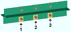
Number of stitch plates: Auto or a user-entered number . This " General settings " option sets the number ( 1 or 2 or 3 ...) of stitch plates.
|
Number of stitch plates = ' 3 '
|
If the box for " Auto " is checked ( ) and a distance is entered to " Max stitch plate spacing ," the minimum number of stitch plates that are required to achieve a spacing that is less than that distance are generated. If " Auto " is checked both here and for " Maximum stitch space spacing ," setup choices are applied from Home > Project Settings > Fabricator > Detailing > Member Detailing Settings > the " Stitch Plates " section.
If the box for " Auto " is not checked ( ), then " Auto " must be checked for " Maximum stitch space spacing " if you want to generate exactly the number of stitch plates that are entered here. Those stitch plates will be equally spaced.
Report Writer: Member.StitchPlateNumber
Report Writer: Member.AutoStitchPlateNumber
Advanced Selection: m.AutoStitchPlateNumber
Parametric module: m.AutoStitchPlateNumber
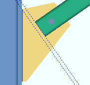
Seismic brace: Automatic or Yes or No . A seismic vertical brace can be designed for any of the usual vertical brace framing situations -- except 3-point braces -- so long as the brace is a valid material type . Be aware that the overstrength factors, " Ry " and " Rt ," which are entered per material type at Home > Project Settings > Job > Material Grades , increase the magnitude of a calculated " Auto " load (" Tension load " or " Compression load "). Connection design does not use " Ry " and " Rt " for user-entered loads.
| VIDEO
|
|
Values for HSS reinforcement plates are filled out automatically when " Seismic brace " is set to ' Yes ' or, with the appropriate setup, to ' Automatic '. To reinforce non-seismic HSS braces, " Brace Reinforcement " locks are available.
|
|
|
' Yes '
|
|
|
|
' No '
|
|
|
|
In the left example, one construction line is drawn along the end of the brace. The other passes through the corner of the gusset. The same construction lines are in the right example.
|
' Automatic ' instructs connection design to apply the choice made to Home > Project Settings > Job > Design Settings > " Seismic vertical brace gusset design ."
' Yes ' specifies that connection design create a seismic connection on both ends of the brace. If " Auto " is selected for the vertical brace's " Tension load " and/or " Compression load ," connection design creates a connection with seismic loading on that end of the vertical brace. If '  SCBF ' is selected for the vertical brace, the " Multiplication factor... " at Home > Project Settings > Job > Plate Design Settings is used to set the distance parallel with the brace member line from the end of the brace (or paddle plate or built-up tee) to the nearest corner of the gusset. For HSS /TS seismic braces, connection design creates reinforcement plates with locks that are contained in the " Brace Reinforcement " leaf ( ) . For 2-point gusset plates, the option " AISC seismic 1st ed. 2pt gussets " sets whether the design is based on the 1st or 2nd edition of the AISC seismic design manual. For 2-point bracing to a column flange, a " Web Doublers " leaf becomes available for the adding of supporting member web doublers. The " Web Doublers " leaf is populated automatically when the supporting member is a thin-web beam or thin-web column. For a seismic vertical brace or 2-point braces to a column web, the " Stiffener Plate " leaf may, if the column web is too thin, be populated with values that generate web stiffeners in the supporting column.
' No ' configures connection design to create a non-seismic connection. The gusset will likely be smaller, and the end of the brace will likely be closer to the supporting member. For 2-point bracing, web doublers will not automatically be designed as needed on the supporting member. Brace reinforcement will not automatically be added for HSS/TS vertical braces. You can still get web doublers for non-seismic 2-point bracing by selecting ' As needed ' for " Check supporting for web shear " in " Connection specifications ." For non-seismic HSS/TS braces, you can still get connection design to create reinforcement plates by entering a " Plate thickness " in the " Brace Reinforcement " leaf.
Steel grade setup for seismic design " Auto " loads:
Factors controlling " Auto " load calculation for seismic design
(per section I-6 of the AISC Seismic Design Manual ) |
|
Steel grade setup
|
Tensile strength
|
Yield strength
|
|
wide flange
|
Rt
|
Ry
|
|
angle
|
Rt
|
Ry
|
|
channel
|
Rt
|
Ry
|
|
welded plate W
|
Rt
|
Ry
|
|
HSS rectangular / TS
|
Rt
|
Ry
|
|
round bar
|
Rt
|
Ry
|
|
W tee
|
Rt
|
Ry
|
|
HSS round / pipe
|
Rt
|
Ry
|
Report Writer: Member.LeftEnd.MoreEnd.SeismicVerticalBraceGussetConnectionDescription
Report Writer: Member.LeftEnd.MoreEnd.DesignedConnection.IsSeismicConnection
Advanced Selection: m.Ends[0].Designed.IsSeismicConnection
Parametric module: m.Ends[0].Designed.IsSeismicConnection
End connection failure message: Seismic brace not allowed with 3 point braces
------------------
Member Information
Main material :  or
or  .
.
Marked for processing :  or
or  .
.
Marked for detailing : or .
Node-match job : or . ( read-only )
Model complete : or . ( read-only )
Model complete date : **NOT SET** or a month day year .
Lift assignment : not assigned or a crane placement name . ( read-only )
------------------
WP to WP length, plan: Read-only . The work point-to-work point distance spanned by this vertical brace's work line in a plan view, ignoring elevation. This " General settings " distance is calculated from the X and Y (but not Z) global coordinates of the vertical brace's work points .
Report Writer: Member.WorkpointToWorkpointLevel
Advanced Selection: m.WorkpointToWorkpointLevel
Parametric module: m.WorkpointToWorkpointLevel
WP to WP length, actual: Read-only . The actual length of this vertical brace's work line . This " General settings " distance is calculated from the X and Y and Z global coordinates of the vertical brace's work points .
Tip: Using Move/Stretch Members or Move/Stretch Members, Include Material to lengthen or shorten a brace or change a brace's " End elevation " on one end causes a different distance to be reported here.
Report Writer: Member.WorkpointToWorkpointSlope
Advanced Selection: m.WorkpointToWorkpointSlope
Parametric module: m.WorkpointToWorkpointSlope
------------------
|
Special Buttons for Detailing
|
 |

|

|

|
|
Press this button to open a window with a list of preset views that you can select. When you Detail the brace, each preset view is drawn on the detail.
|
Press this button to open a list of views you can delete. If the brace has only a main view, you get a warning instead of a list of views since you cannot delete the main view.
|
This button opens the Annotations... window. Press " OK " on that window to detail the brace(s). Newly added views will be drawn. Deleted views will not be drawn.
|
Press this button to start up the Drawing Editor . You will automatically be shown the detail of the brace if it has been detailed and if the file is not currently open.
|
Multi-edit: The " Detail Member " button is enabled when you are multi-editing vertical braces with different piecemarks, allowing you to Detail those braces. The other buttons will be disabled ( grayed out ) for multi-edit operations, although you can " View detail " if the multiple vertical braces being edited have the same mark.
Note 1: If you add or delete a view or detail this member using these buttons, the " Marked for detailing " button updates immediately.
Note 2: " Freeze drawing " in the Drawing Editor disables ( grays out ) the " Add View " " Delete View " and " Detail Member " buttons.
or . " Lock End "
disables ( grays out ) all options under [ Left end settings ] or [ Right end settings ] (as the case may be), thus preventing users from making changes to the connection.
" Copy " and " Save " form buttons remain active. You can also still make changes to " General settings " and the other end's settings.
The material, hole, bolt and weld edit windows for system connection materials associated with this end of the member became read-only.
Furthermore, Delete or Erase cannot remove any of this connection's materials, holes, bolts or welds. Cut Layout , Add Holes , and similar material altering operations cannot be performed on any of the connection's materials. Such operations can only be performed on the member main material.
The member main material's setbacks and end preparations will become read-only.
Locking a member's end does not inhibit operations that you can normally perform on the member main material -- such as Cut Layout or Add Holes -- nor does it stop you from applying Custom Properties to the locked connection material.
allows the editing of options under [ Left end settings ] or [ Right end settings ] (as the case may be).
Status Update: Lock left/right end
Status Display: Approval and modeling > Member left end locked
 /
/  " Lock All Lockables" / "Unlock All Lockables "
|
Connection design locks set. |
|
|
| Tip: Pressing the " Unlock All " button clears the above message .
|
|
sets all " End preparations " and " Connection design locks " under [ Left end settings ] or [ Right end settings ] (as the case may be) to a locked state, thus preventing the connection from being altered by connection design . You will still be able to make changes to the connection by unlocking ( ) particular lockable fields (so that connection design can make entries to that field) or by you yourself making different entries to the locked fields.
unlocks all connection design locks associated with the left or right end (as the case may be). This results in a connection that is fully designed by connection design, without any user entries to connection design locks.
 Save As User Defined Connection: This button is available when you are editing one member at a time. It is not available if you are editing multiple vertical braces. It allows you to save as a user defined connection changes that you have made to connection design locks and to other [ Left end settings ] or [ Right end settings ]. You can overwrite a previously saved user defined connection or create an entirely new user defined connection.
1. When you are done adjusting the connection's settings, click the Save As User Defined Connection button.2. The Select one User Defined Connection window opens. Click the New... button to create a new user defined connection using the current Connection specifications, connection design locks, and Moment options you have set.
Alternative 1: To save over an existing user defined connection and replace its settings with the current settings of the edit window, select it and click OK or double-click it. Click Yes or No on the prompt window asking if you want to overwrite the connection. The user defined connection is immediately saved. There are no further steps to take.
Alternative 2: Click the Cancel button to close the Select one User Defined Connection window.
3. The User defined connection name input window opens. Type in a name for the connection (61 characters max.) and click OK to save the new user defined connection.
Alternative: Click the Cancel button to close the User defined connection name input window and return to the Select one User Defined Connection window.
" Copy " " Paste " " Save " " Load "
- These are sometimes referred to as "form buttons."
- You can use these buttons to save and copy connections. The buttons operate on all fields under all leaves that are under the [ Left end settings ] or [ Right end settings ] heading.
- For more information, see "Copy" "Paste" "Save" "Load" .
Connection: Force and/or Graphical or a System connection . This " Information " option and its related messages apply when the vertical brace end's " Input connection type " is a choice other than ' Plain end '.
' Force ' applies when the connection has failed , which results in your not getting any connection materials in the 3D model.
To get connection materials so that you can assess the situation and make needed changes, check the box for " Force ." The Connection Design Calculations report (and Expanded Connection Design Calculations ), will include a warning that the connection has been forced. Example: Suppose you get the end connection failure message " Gusset extends past the end of the member " instead of a gusset plate. Checking the box for " Force " is a possible way to get a gusset plate. Although the gusset plate will probably have obvious flaws and not be of much use, seeing it may help you to better understand why the connection failed and how you can fix it.
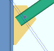
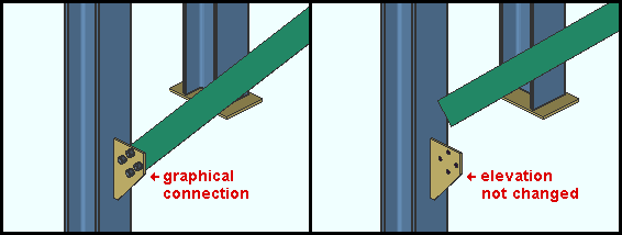
' Graphical ' may have been set to " Graphical " automatically by connection design as a result of a user employing modeling operations to modify the system connection on this end of the member, thus making it graphical .
A graphical connection will not be changed by connection design . On this window, you will not be able to change any of that connection's " End preparations " and " Connection design locks ." The Connection Design Calculations report (and Expanded Connection Design Calculations ) will include the warning " GRAPHICAL CONNECTION -- STRENGTH CALCULATIONS NOT GENERATED ." If " Graphical " is checked and you switch it to " Graphical " then press " OK " (so that Create Solids is performed), user-added modifications to that connection will be overwritten or erased. For example, user-added holes will disappear. On the General Information window for each of the connection materials, you will see that switching from " Graphical " to " Graphical " caused the connection materials that were regenerated to be changed from " User modified connection material " to " System created connection material ."
Search and Change:
Status Display: Search > Graphical connections
Report Writer: Member.LeftEnd.MoreEnd.Settings.ForceConnection
Report Writer: Member.LeftEnd.IsGraphicalConnection
Advanced Selection: m.Ends[0].ForceConnection
Advanced Selection: m.Ends[0].IsGraphicalConnection
Parametric module: m.Ends[0].ForceConnection
Parametric module: m.Ends[0].IsGraphicalConnection
" Connection design locks set ," end connection failure messages, other messages :
If you are in a multi-user environment, a member edit window could be opened at the same time somebody else is adding a member that connects to that member. As a result, Process within member edit will be locked from accessing information about that opened member, and the following message will be generated:
|
On-the-fly process failed
|
If you are editing multiple vertical braces and those braces have different connection failed or connection changed messages, you get a banner like the following:
|
Multiple failed and/or changed connection messages |
The following banner notifies you that the connection has at least one " Connection design lock " or " End preparations " setting that is locked (  ):
):
|
Connection design locks set.
|
| VIDEO
|
|
Sections of a window (" leaves ") within which at least one locked variable resides are marked (in the navigation tree) with a locked icon ( ).
|
|
Search: Connection design locks set
Status Display: Search > Connection design locks set
User and Site Options > Modeling > " Process within member edit " > ' Off '' gets you the following banner:
The option "Process within member edit" has been disabled.
Values on this screen may change after process.
|
You may find a red connection failure banner like that shown below along with a  button for context-sensitive help about the message:
| Gusset extends past the end of the member
|

|
|
for help on the end connection failure message that is shown
|
Report Writer: Member.LeftEnd.ConnectionHasFailed
Report Writer: Member.LeftEnd.MoreEnd.Conditions.ConnectionFailError
Advanced Selection: m.Ends[0].ConnectionHasFailed
Parametric module: m.Ends[0].ConnectionHasFailed
You will find a yellow " Frames to ... " banner on this end of this vertical brace if this end of the vertical brace frames to a member (beam or column or other vertical brace) that has its " Model complete date " set. Connection design may add the message (possible inaccurate connection) to the banner, or connection design may fail the connection on this end (the banner end) with the error message: Frames to a Model Complete member .
Frames to a Model Complete member
(possible inaccurate connection)
|
Model complete type: Restricted or Legacy
Setup: Home > Project Settings > Job > Member and Drawing Restrictions
Also see: Lock Ends Framing to Model Complete Members
To move between the " End elevation " for the left end and right end of this brace, press the comma key [,] on your keyboard.
End elevation: The elevation (in the primary dimension " Units " or other units ) of the work point at this end of the vertical brace.
Work point alignment: The work points of a vertical brace align with the neutral axis of a wide flange , HSS round or HSS rectangular vertical brace. For a W tee vertical brace, the work points align with the top flange center line if the stem is ' Horizontal ' or along the centroid if the stem is ' Vertical '. For a single angle vertical brace, the work points align with the gage line of the angle (the vertical dimension from the heel of the angle to the first hole). For a channel vertical brace, the work points align with the half-depth line of the heel of the channel (the channel web is vertical).
Note 1: " Copy " " Paste " " Save " " Load " buttons do not operate on the " End elevation ."
Note 2: If you are editing one vertical brace with a piecemark shared by at least one other vertical brace and change its " End elevation " on one or both ends, you will get a notification dialog after you press " OK " to close this window. The notification dialog will remind you that you have the option to change the elevations of all vertical braces with the same mark. If you choose to change the elevations of all vertical braces with the same mark, the ends of the members will be moved in the same manner and by the same relative amount (not necessarily to the same elevation).
To determine a vertical brace's end elevation in the 3D model, start up a tool such as Construction Line Add , select EXPT as the Locate option, then move the point location target to the work point at the end of a vertical brace and reference the Z coordinate reported in the X-Y-Z display .
Report Writer: Member.LeftEnd.LocationZ
Advanced Selection: m.Ends[0].Location.z
Also see: Set Vertical Brace Workpoints to 1/2 Nominal Depth of Supporting Beam (a change option).
Move material: or . This " Member " option applies when you change the left-end " End elevation " and the left-end " Connection " is set to " Graphical " or the " Main material " has been set to ' SYSTEM ' or a user has added holes or materials to the member. In other words, it may apply when the vertical brace has user-added holes, user modified connection material , user modified member main material or user created material .
Before increasing the left-end
" End elevation "
|
After increasing the left-end
" End elevation "
|
|
| Example : The left-end " Connection " is set to " Graphical ". The Main material is set to . To get the " after " example, the left-end " End elevation " was raised 1 foot with " Move material " not checked.
|
|
If this box is checked ( ), the user-added or user-modified material (as well as holes) will move with the left end of the vertical brace when the member's left-end " End elevation " is changed. In other words, the user material will behave like system connection material.
If the box is not checked ( ), the user-added or user-modified material will remain in place when the member's left-end " End elevation " is changed.
Default: When this window first opens, the box for " Move Material " is checked ( ) or not checked ( ) based on the choice made to User and Site Options > Modeling > " Maintain user material and holes relation to vertical column/vertical brace member left end ."
Why only the left end: The " Move material " option is available only for the left end (end zero) of a vertical brace because, in this program's code, user-added materials and main material user-added holes are positioned along a member based on their distance from the member's left end.
Also see: Move/Stretch Member, Include Material , Move material ( Column Edit window, bottom end)
Standard detail: None or a standard detail name . To apply a standard detail, you can type in the file name of the drawing (if you know it), or press the "file cabinet" browse button ( ) and double-click any job standard detail or global standard detail that is on the list.
If ' none ' is entered here, then no standard detail will be applied on this end of the vertical brace when the brace is automatically detailed .
If a ' standard detail name ' is entered here, the next time you auto detail this vertical brace, the reference point of the standard detail will align with the input work point on this end of the brace, and the standard detail's bill of material will be combined with the brace's bill of material. The detail is placed on a layer that is named after the standard detail plus a "_L " or " _R " suffix.
Report Writer: Member.LeftEnd.MoreEnd.StandardDetailFileType
Report Writer: Member.LeftEnd.MoreEnd.StandardDetailFileNumber
Report Writer: Member.LeftEnd.MoreEnd.StandardDetailFileName
Advanced Selection: m.Ends[0].StandardDetailFileNumber
Advanced Selection: m.Ends[0].StandardDetailFileType
Parametric module: m.Ends[0].StandardDetailFileNumber
Parametric module: m.Ends[0].StandardDetailFileType
Input connection type: User defined or Plain end or Vbrc plate or Welded .
If ' User defined ' is selected, the user defined connection file name must be entered to " User defined connection ."
' Plain end ' prevents a system connection from being created on this end of the vertical brace, presumably so that the user can manually create the desired connection. Connection design will generate appropriate setbacks to prevent interference with any members the brace frames to. Also, you can set both ends of the brace to ' Plan end ' and still get stitch plates . Tip : Use Add Assembly to add a connection to a member with a plain end.
' VBrc plate ' instructs connection design to create a system connection -- a gusset plate -- on this end of the brace. System gusset plates are designed per the framing situation and the " Connection specifications " settings for this end of the brace. Different gusset plates are designed for brace-to-beam, brace-to-column and brace-to-beam & column framing situations. Also, the materials used for the brace and framed-to members affect the gusset design. For an angle , W tee or channel vertical brace framing to a beam and column, connection design creates the gusset-to-column interface with the same connection type that is designed for the beam as long as that connection type is a clip angle or shear plate or end plate . In other words, if the beam connects to the column with a shear plate, so will the vertical brace.
' Welded ' can be used for creating trusses and fully-welded connections. Connection design can create a welded connection in the following situations:
For an HSS ( pipe or tube ) vertical brace to an HSS chord member (beam): The program Exact Fits this pipe brace to the other HSS brace or chord member, then welds the sections. For 3-point HSS braces (tube or pipe), the center brace fits to the chord and the other braces fit to the center brace. For 2-point braces , the brace with the lower member number [num] fits to the chord. The " Field clearance " sets the fit clearance to the cord or other brace. Click here for examples.
For an HSS ( pipe or tube ) vertical brace to a wide flange beam, column, or vertical brace flange: Connection design fits the end of the pipe or tube
flush to the supporting member's flange and welds it with an all-around fillet weld. Transverse stiffeners might also be created on the supporting member to stiffen the web. For setup of this connection, see " Plate Design Settings ".
Double-angle vertical brace (' Back to back ') to the stem of a W tee (or S tee) chord member (beam): Connection design welds the angles to the stem of the tee. For setup of this type of brace, see " Brace to supporting member " (field clearance), " Brace to brace " (field clearance), " Weld all around angle branch ," " Connection weld size " and " Type of spacer for welded connections ." Click here for examples.
Process within member edit takes place when a different Input connection type is selected.
" Connection specifications " and " Connection design locks " provide settings for finer control of a connection's design.
Report Writer: Member.LeftEnd.MoreEnd.InputConnection.TypeDescription
Advanced Selection: m.Ends[0].Input.TypeDescription
Parametric module: m.Ends[0].Input.TypeDescription
User defined connection: The file name of the user defined connection in your current Job that you want applied when this vertical brace end's " Input connection type " is ' User defined '.
To make an entry: You can type in the file name of the user defined connection that you want, or you can press the "file cabinet" browse button (  ) and double-click any user defined connection file name that is on the list.
Status Display: Connection type > Specific user defined connection
Report Writer: Member.Conditions.HasAUserDefinedConnection
Advanced Selection: m.Ends[0].FinalConnectionIsUserDefined
Parametric module: m.Ends[0].FinalConnectionIsUserDefined
System designed connection: Read-only . The type of connection that connection design created on this end of the vertical brace (e.g., ' Vbrc plate ' or ' Plain end '). If a connection has failed , resulting in no solids model being created, the connection type that connection design attempted to design will still be reported here. The "System designed connection " may be different than the " Input connection type " in the following situation:
If ' User defined ' is the selected " Input connection type ," the specific designed connection type is reported here. Press the " Design Calc " or " Expanded Calc " button for more information about that connection.
Report Writer: Member.LeftEnd.MoreEnd.DesignedConnection.TypeDescription
Advanced Selection: m.Ends[0].Designed.TypeDescription
Parametric module: m.Ends[0].Designed.TypeDescription
NM bolt type: Auto or A325N or A325SC or A325X or etc. NM stands for "non-moment." This bolt type will be used to bolt the gusset plate to the brace .
If " Auto " is checked ( ), connection design applies the non-moment " Bolt type " set at Home > Project Settings > Job > Bolt Settings . When, in Connection specifications " the " Pipe/tube end fitting " is set to ' Welded ', connection design uses the bolt type specified for Bolt Settings > HSS welded brace erector bolts .
If " Auto " is not checked ( ), then you can select a bolt type from the list box (  ). The bolts that are listed come from Home > Project Settings > Job > Bolts, Washers and Holes > Bolt Settings .
Bolt diameter controls row spacing: " Bolt spacing "
Advanced Selection: m.Ends[0].ConnectionDesignBoltTypeDescription
Advanced Selection: m.Ends[0].NonMomentBoltTypeWasInput
Parametric module: m.Ends[0].ConnectionDesignBoltTypeDescription
Parametric module: m.Ends[0].NonMomentBoltTypeWasInput
NM bolt diameter: Auto or a user-entered diameter (inches or mm). This " Connection type " option sets the diameter of the shanks of the bolts that fasten the gusset plate to this end of the vertical brace .
|
diameter
|

|
If " Auto " is checked ( ), connection design applies the non-moment " Bolt Diameter " set at Home > Project Settings > Job > Bolts, Washers and Holes > Bolt Settings . When, in " Connection specifications " the " Pipe/tube end fitting " is set to ' Welded ', connection design uses the bolt diameter specified for Bolt Settings > HSS welded brace erector bolts .
If " Auto " is not checked ( ), you can either type in the diameter of bolt, or select a bolt from the combo box ( ). The diameters that are listed in the combo box come from the " Available bolts " list at Home > Project Settings > Job > Bolts, Washers and Holes > Bolt Settings .
Bolt incrementation: Connection design may increment bolt diameters on brace gusset plates when, for example, " Rows " and " Columns " are locked . The diameter that is entered here should always be the diameter that is used for the gusset-to-brace interface when all connection design locks are unlocked.
Bolt diameter controls edge distance: " Minimum edge distance for xx diameter bolts "
Report Writer: Member.LeftEnd.MoreEnd.MinimumNonMomentBoltDiameter
Advanced Selection: m.Ends[0].MinimumNonMomentBoltDiameter
Parametric module: m.Ends[0].MinimumNonMomentBoltDiameter
Use miscellaneous plates list: or .
If this box is checked ( ), connection design looks to Home > Project Settings > Fabricator > Standard Fabricator Connections > Preferred Plate Sizes to determine the plate thicknesses to be used for vertical brace gusset plates, paddle plates for pipe and tube braces, built-up tee end fittings for pipe and tube braces, paddle plates for wide flange vertical braces, and web connection plates for wide flange braces. First connection design determines the thickness of the plate required to stand up to the load, then it chooses the plate from the list that is the calculated required thickness or the next thicker. If the plate from the list results in material interferences or too narrow a clearance, connection design fails the end connection and gives you the failure message, " Suitable plate thickness not found ."
If the box is not checked ( ), connection design rounds the calculated required thickness of plates as based on the load to the next 1/16 inch (or 1/8 inch if the calculated required thickness is greater than 5/16 inch).
Related options: " Round flat plate values " (affects gusset thickness), " Design by first incrementing gusset thickness or size " (affects gusset thickness), " Minimum gusset thickness " (affects gusset thickness).
Minimum setup connection: Automatic or Yes or No . For a minimum setup connection to be designed, the governing " Loads " on this window must be set to " Auto ". After the connection is designed, the values reported for the " Auto Tension load " and/or the " Auto Compression load " will be the capacity of the connection instead of the allowable load. The Connection Design Calculations and Expanded Connection Design Calculations reports will also report the minimum setup connection's capacity.
' Yes '

|
' No '
|
If ' Automatic ' is selected, connection design applies the choice made to " Minimum setup connection " at Home > Project Settings > Job > Design Settings .
' Yes ' instructs connection design to, instead of calculating the " Loads " that are set to " Auto " on this window, apply minimal values for those loads, and thus create a connection with the minimum number of bolt rows, the minimum gusset plate thickness, etc. A green banner in the " Loads " section of this window will notify you that the connection has been designed with the " Minimum setup connection capacity ." A minimum setup connection probably will not stand up to the loading conditions that the actual connection will be subjected to in the built structure. For this reason, you will probably want to build up the connection using connection design locks .
' No ' instructs connection design to create the connection on this end of the brace to stand up to the governing " Auto " " Loads ." " Auto " loads are calculated according to choices made to " Percent of allowable tension load " or " Percent of allowable compression load " in Design Settings .
Tip: Instead of choosing ' Yes ' for " Minimum setup connection ," you can enter a minimal value such as 6 kips for the load that governs the design of the connection -- for example, the " Tension load ." The resulting connection will effectively be a minimum setup connection.
Report Writer: Member.LeftEnd.MoreEnd.MinimumSetupConnectionDescription
Report Writer: Member.LeftEnd.MoreEnd.DesignedConnection.IsMinimumConnection
Advanced Selection: m.Ends[0].Designed.IsMinimumConnection
Advanced Selection: m.Ends[0].MinimumSetupConnection
Parametric module: m.Ends[0].Designed.IsMinimumConnection
Parametric module: m.Ends[0].MinimumSetupConnection
Disable framing situation checks: or .
If this box is checked ( ), framing situation checks are turned off. If you get the failure message " Conn modified by framing situation, see design calc ," then checking this box should clear that message. However, connection design may still fail the connection, resulting in your getting a different failure message in its place.
If the box is not checked ( ), framing situation checks are turned on.
" Connection specifications " is populated with options when this vertical brace end's " Input connection type " is ' Vbrc plate ' or ' Welded '. There are no " Connection specifications " options -- just an empty leaf -- when the " Input connection type " is ' User defined ' or ' Plain end '.
For more information, click a link :
---- Vbrc plate ----
---- Welded ----
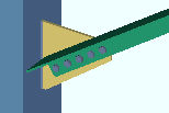
Field clearance: If this " Setbacks " option is selected ( ), you can set the distance between the end of the brace and the face of the supporting beam or column. Or this may be the distance between the end fitting on the brace and the face of the supporting beam or column. Or it may the distance between the end of the brace and the edge of the clip angle that bolts the gusset to the supporting member. For a ' Welded ' HSS (pipe or tube) brace to an HSS chord member, the " Field clearance " is the fit clearance to the chord or other brace.
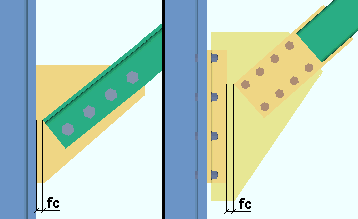
|
fc = field clearance
|
Status Display: Member status > Left end field clearance and Right end field clearance
Report Writer: Member.LeftEnd.FieldClearanceFlag
Report Writer: Member.LeftEnd.MoreEnd.FieldClearance
Advanced Selection: m.Ends[0].FieldClearanceFlag
Advanced Selection: m.Ends[0].FieldClearance
Parametric module: m.Ends[0].FieldClearanceFlag
Parametric module: m.Ends[0].FieldClearance
Input minus dimension: If this " Setbacks " option is selected ( ), you can type in the distance to bring the end of the vertical brace back from the work point for that end. Increasing the minus dimension makes the vertical brace shorter, sets it farther away from the supporting member, and increases the length of the gusset plate.
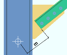
|
m = minus dimension
|
Status Display: Member status > Left end minus dimension and Right end minus dimension
Report Writer: Member.LeftEnd.MoreEnd.MinusDimension
Advanced Selection: m.Ends[0].MinusDimension
Parametric module: m.Ends[0].MinusDimension
Automatic minus dimension: If this " Setbacks " option is selected ( ), then connection design calculates the minus dimension for you, taking into account the brace's " Brace to other member " field clearance, the " Minimum edge distance ," and the depth or web thickness of the supporting member. The " Automatic minus dimension " may also be adjusted for changes made to connection design locks .
Status Display: Member status > Auto minus dimension (either end)
Status Display: Member status > Left end minus dimension and Right end minus dimension
Report Writer: Member.LeftEnd.MoreEnd.Settings.AutoMinusDimension
Advanced Selection: m.Ends[0].AutoMinusDimension
Parametric module: m.Ends[0].AutoMinusDimension
Warning : Loads entered here affect the design of vertical brace connections. Users should enter loads only at the direction of a qualified engineer.
A banner like the following appears at this location if the connection on this end of the brace is a " Minimum setup connection ." The " Auto Tension load " and/or the " Auto Compression load " will report the capacity of the connection instead of the allowable load.
|
Minimum setup connection capacity
|
Tension load (kips or kN) : Auto or a user-entered load in kips (kilonewtons for ' Metric '). A tension load tends to stretch the member in the direction of its length.
| Tension load: Auto |
|
|
or
|
| Tension load: Auto |
|
If the box for " Auto " is checked ( ), the tension load on this end of the brace is automatically calculated using the value entered to " Percent of allowable tension load for vertical braces " or " Percent of allowable tension load for intersection vertical braces " at Home > Project Settings > Job > Design Settings . The calculated numerical value -- calculated in this example -- is shown in grayed-out text to indicate that it cannot be changed so long as " Auto " is checked. A special case : The calculated value shown here for a " Minimum setup connection " is the connection's tension capacity, rather than its allowable tension load. Design method considerations: For ' ASD ' or ' LRFD ', the " Auto " tension load is calculated in accordance with Section D2. For ' CISC 8 ' or ' CISC 9 ', it is calculated in accordance with Clause 13.2. For ' AS 4100 ', it is calculated in accordance with Clause 7.2. Another special case: " Seismic brace " design increases the magnitude of the calculated auto tension load.
If the box for " Auto " is not checked ( ), you may enter a tension load (to a desired precision) in the units specified (here) in parentheses. Right-click shows you the currently entered value to the full precision that connection design uses in its calculations. See the warning before entering a load. Also be aware that, if the connection has passed, when you switch from " Auto " to " Auto ," the " Maximum tension load " will be reported, indicating the tension capacity of the connection as it is currently designed.
Status Display: Member status > Left end tension load and Right end tension load
Status Display: Connection auto loads > Auto vertical brace tension
Change Options: Vertical Braces from Input to AUTO Tension Load
Report Writer: Member.LeftEnd.MoreEnd.Settings.AutoTensionLoadCalculation
Report Writer: Member.LeftEnd.MoreEnd.TensionLoad
Advanced Selection: m.Ends[0].AutoTensionLoadCalculation
Advanced Selection: m.Ends[0].TensionLoad
Advanced Selection: m.Ends[0].MaxTensionWithoutFailing
Parametric module: m.Ends[0].AutoTensionLoadCalculation
Parametric module: m.Ends[0].TensionLoad
Parametric module: m.Ends[0].MaxTensionWithoutFailing
Also see: " Show design loads on vertical brace details " (Fabricator Setup > Member Detailing Settings > " Vertical Braces " section)
Compression load (kips or kN) : Auto or a user-entered load in kips (kilonewtons for ' Metric '). A compression load tends to compress or shorten the member.
| Compression load: Auto |
|
|
or
|
| Compression load: Auto |
|
If the box for " Auto " is checked ( ), then the compression load on this end of the brace is automatically calculated using the value entered to " Percent of allowable compression load for vertical braces " or " Percent of allowable compression load for intersection vertical braces " in Design Settings . The calculated numerical value -- calculated in this example -- is shown in grayed-out text to indicate that it cannot be changed so long as " Auto " is checked. A special case: The calculated value shown here for a " Minimum setup connection " is the connection's compression capacity, rather than its allowable compression load. Design method considerations: For ' ASD ' or ' LRFD ', the " Auto " compression load is calculated in accordance with Section E3. For ' CISC 8 ' or ' CISC 9 ', it is calculated in accordance with Clause 13.3. For ' AS 4100 ', it is calculated in accordance with Clause 6.3. Another special case: " Seismic brace " design increases the magnitude of the calculated auto compression load.
If the box for " Auto " is not checked ( ), you may enter a compression load (to a desired precision) in the units specified (here) in parentheses. Right-click shows you the currently entered value to the full precision that connection design uses in its calculations. See the warning before entering a load. Also be aware that, if the connection has passed, when you switch from " Auto" to " Auto ," the " Maximum compression load " will be reported, indicating the compression capacity of the connection as it is currently designed.
Status Display: Member status > Left end compression load and Right end compression load
Status Display: Connection auto loads > Auto vertical brace compression
Report Writer: Member.LeftEnd.MoreEnd.Settings.AutoCompressionLoadCalc
Report Writer: Member.LeftEnd.MoreEnd.CompressionLoad
Advanced Selection: m.Ends[0].AutoCompressionLoadCalculation
Advanced Selection: m.Ends[0].CompressionLoad
Parametric module: m.Ends[0].AutoCompressionLoadCalculation
Parametric module: m.Ends[0].CompressionLoad
Also see: " Show design loads on vert brace detail " (Fabricator Setup > Member Detailing Settings > " Vertical Braces " section).
- A left- and right-end " Summary " can be shown on this window only if you are editing one vertical brace. There is no summary if you are editing multiple vertical braces.
- The " Summary " leaf gives you a summary of connection information related to the left or right end of the vertical brace.
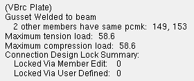
- The summary shows (in parentheses) the " System designed connection ."
- If other vertical braces have been assigned the same piecemark as this vertical brace, the summary lists those other vertical braces by member number (149 & 153 in this example). These are the vertical braces that will be changed if, after you close this window, you press the " Yes " button when prompted to change all .
- If this vertical brace is part of a group member, the summary lists the group member piecemark .
- The " Maximum tension load " and " Maximum compression load " show the capacity of the connection.
- " Connection design locks " and " End preparations " that were locked ( ) because the " Input connection type " is ' User defined ' are reported as " Locked Via User Defined ." All other locks that are locked ( ) are reported as " Locked Via Member Edit ."
- Here are some related options:
Advanced Selection: m.PiecemarkCount
Parametric module: m.PiecemarkCount
| VIDEO
|
|
You can lock all or unlock all connection design locks in a section (under a leaf ).
|
|
End preparation settings that are similar to these can be found on the Rolled Section Material window. However, those settings cause the " Main material " to be set to ' ' and the affected " Connection " to be " Graphical ".
These settings keep the " Main material " set to ' ' and do not make the connection graphical.
End-cut type
Web cut angle
Flange cut angle
Moment connection web setback
Top flange operation : ' None ' or ' Cope plain ' or ' Cope field weld #3 (Standard) ' or ' Cope shop weld #3 (Standard) ' or ' Cut flange width ' or ' Cut flange flush ' or ' Clip flange ' or ' Notch ' or ' Notch NS/FS ' or ' Cope field weld #1 (FEMA) ' or ' Cope shop weld #1 (FEMA) ' or ' Clip web ' or ' Seismic cope field weld ' or ' Seismic cope shop weld '.
Bottom flange operation : Same as above.
- This documentation categorizes connection design locks by framing situation.
Vertical Brace to a Beam
( or various framing situations ) |
|
|
Vertical Brace to a Column
|
|
|
Vertical Brace Intersection (X bracing) |
|
|
Vertical Brace to a Beam & Column
|
|
|
Vertical Brace 2- or 3-Point Shared Gusset to a Beam
|
|
|
Vertical Brace 2- or 3-Point Shared Gusset to a Column
|
|
|
Vertical Brace to a Column & Base/Cap Plate
|
|
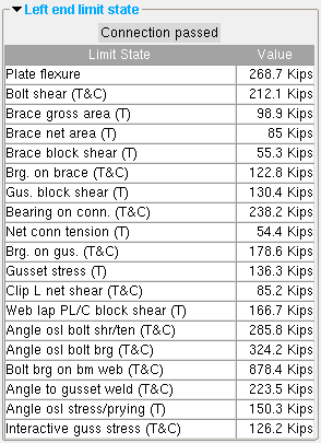 |
These limit states are for a stem-vertical tee brace with a web plate connection to the gusset. A clip angle connects the gusset to the supporting beam. The values shown represent the strength capacity of the connection or of the supported member (this vertical brace). In this example, the connection passes.
(T) = tension
(C) = compression
|
| VIDEO | |
Limit states are placed below the navigation tree when the left-end or right-end settings are collapsed.
|
|
- A limit state is a potential connection failure mode. Each " Value " reported in the example above represents the strength of the connection or of the brace itself or of the supporting member with respect to a particular limit state.
- The capacity of a connection is calculated for various limit states during connection design , and the left-end and/or right-end limit states tables on this window will be updated any time that connection design takes place.
- When Process within member edit is turned on, node matching, connection design and framing situation checking takes place within this window, on-the-fly, whenever you change a connection specification or a load or connection design lock or any other connection-related setting.
- If connection design determines that the capacity of a connection is insufficient to stand up to the " Loads " on the vertical brace, or if there is a geometry problem related, for example, to the work points of the brace, connection design fails the end connection and generates a failure message such as:
| Gusset extends past the end of the member |
- When you make changes to connection design locks , referring to the reported limit states can help you to better assess how your changes affect the capacity of the connection.
- The Expanded Connection Design Calculations provides formulas and the calculations that relate limit states to the design of the specific connection.
- The following custom components are shipped with SDS2, and you therefore can potentially find on the Vertical Brace Edit window a section for them with one of the following names:
- Custom component settings will be shown on this window only after a custom component has been added to this vertical brace (using Model > Component > Add ).
- Settings for custom components from outside distributors may also be shown on this window. However, since such custom components are not distributed by SDS2, they are not documented in this help manual.
- To delete a custom component, you can right-click that component's listing on the Vertical Brace Edit window's navigation tree , then choose " Delete " on the context menu.
- Tip: An alternative to editing a custom component on this window is to double-click material generated by that custom component in the model. This opens that custom component's edit window. That edit window includes all the settings for that custom component, but does not include other settings for the vertical brace.

"Copy" "Paste" "Save" "Load" apply to all fields on this window. They do the same thing as the "Copy" "Paste" "Save" "Load" buttons ( ) found in the header portion of individual leaves on this window -- except that they apply to the entire window instead of an individual leaf or section.
"Properties" opens the Edit Properties window, on which you can make entries to custom properties . If, at the time it was created, your current Job was set to use a legacy flavor, the window that opens is named Custom Properties , not Edit Properties .
The Edit Properties window can also be used to read " Log " entries or review or type " Notes ."
Tip: Model > Member > Properties is an alternative to this button. It opens the Edit Properties window directly, without your first having to open a member edit window.
" Status " opens the Member Status Review window, which can give you additional information about this vertical brace, and which you can use to enter status information or designate a member as an " Existing member ."
Note: This button is orange if one or more " Repeat " check boxes on the Member Status Review window do not match the checked-unchecked state of same-named fields in User and Site Options > Site > " Items to Copy/Repeat ." On the Status Review window, the fields that do not match User and Site Options are printed in red .
" OK " (or the Enter key) closes the Vertical Brace Edit window and saves any changes you have made on the window to the 3D model of your current Job .
Solids on "OK": If the appropriate choice is made to User and Site Options > Modeling > " Automatically process after modeling operation ," then this member will automatically be regenerated ( Create Solids will take place) after your press " OK ." Otherwise, you will have to manually Process and Create Solids in order for changes you made on this window to be fully updated in the 3D model.
Change all: If you Edit Member (one vertical brace only) and make a change that potentially triggers the " Do you want to change all ... " dialog and the 3D model contains more than one vertical brace that has the same piecemark as the vertical brace you changed, a yes-no dialog opens. On it is the question, " Do you want to change all (members with this piecemark). " Press the " Yes " button to change all the members; press the " No " button to change only this vertical brace. Special cases are listed on the table below:
Option to lock ends of framing members: If you changed the " Model complete date " on this vertical brace and other members have connections to this member, the Lock Ends Framing to Model Complete Members window opens, giving you options to " Lock ... " the ends of those members that frame to this member.
Defaults for to-be-added vertical braces: If you are adding a vertical brace and you press " OK ," the settings on this window except " Swap member ends " become the default settings for the next vertical brace you Add in this session of Modeling . Even if all you do is double-click a vertical brace and press " OK " without making any changes on this window, this window's settings become the defaults for the next-added vertical brace. On the other hand, the settings on this window do not become the defaults for new braces if you are editing multiple piecemarks or if you press " Cancel " to close this window.
" Cancel " (or the Esc key or the  button) closes this window without saving any changes. " Cancel " does not undo a " Detail Member " operation.
Note: If you opened this window using Add Vertical Brace, pressing " Cancel " brings you back to the work point location step of adding a vertical brace.
Tip: Any time you use Edit Member just to review a member (and you do not want to set the defaults for to-be-added members), the best way to close this window is to press " Cancel. "
" Reset " undoes all changes made to this window since you first opened it. The window remains open.
Exception: Pressing " Reset " does not undo a " Detail Member " operation.
"Design Calcs" outputs the Design Calculations report (also referred to as Short Calcs) which includes design calculations, general settings, and left/right end settings. A report for each vertical brace you are editing is output to a destination of your choice as a PDF file. The file automatically opens with your operating system's default PDF application when you are editing one vertical brace at a time.
"Expanded Calc" outputs the Expanded Connection Design Calculations . First a PDF of the report is output to a destination of your choice. For example, to your desktop. Then the report automatically opens with your operating system's default PDF application.
Expanded Connection Design Calculations give you the calculation results found in the Connection Design Calculations , plus show you the calculations written out, in detail, in the report itself, instead of simply reporting the results.
If you are editing multiple vertical braces with the same piecemark (or different piecemarks), you get a report for each brace.
Connection design failures can be found with the aid of a search or by a quick scan of the document. Calculations that result in a connection failure are identified as " (NO GOOD) " in their concluding line. You might also search for the string "CONNECTION DESIGN FAILURE".
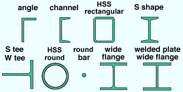


 ) connection design locks are values entered by connection design routines . Many of the unlocked fields are populated based on user-entered setup choices.
Information

