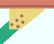
'Vbrc plate' ("  Connection specifications " and more)
On this page :
- Topics:
- Connection specifications:
Also see :
Framing situations determine vertical brace connection design :
The framing condition sets the basic connection design of a vertical brace gusset plate. Users control setup options , connection specifications , and connection design locks .
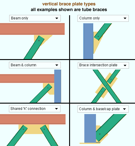
------ Setup of 'Vbrc plate' connections ------
General setup options :
If the gusset connects to the supporting member with a clip angle :
- The various " Clip angle connection of gusset to supporting member " settings under the " Vertical Brace " section in Member Detailing Settings either set defaults for similar options on the Vertical Brace Edit window or apply directly.
Seismic connections :
Vertical braces with shared gussets :
- " Design for shared gusset if plates are closer than " at Home > Project Settings > Job > Plate Design Settings lets you set how close you want vertical braces to be to each another before connection design can create a shared gusset for them.
Wide flange vertical braces :
- Setup for ' Automatic ' web-vertical wide flange vertical brace ' Standard ' connections is done using the Home > Project Settings > Job > Design Settings options " Wide flange vertical brace gusset web connection " (
 ) and " Wide flange vertical brace gusset flange connection ."
- The Preferred Angle Sizes setup list at Home > Project Settings > Fabricator > Standard Fabricator Connections is searched for suitable angle sizes when ' Web claw angles ' is selected for " Connection arrangement ." If connection design can't find a suitable angle in the setup list, it searches the local shape file .
HSS vertical braces :
- " HSS erection bolts " at Home > Project Settings > Fabricator > Member Detailing Settings > " Vertical Braces " sets the default for a similar option on the Vertical Brace Edit window.
Angle vertical braces :
------ " ![]() Connection specifications " for ' Vbrc plate ' connections ------
Connection specifications " for ' Vbrc plate ' connections ------
Gusset plate grade: Auto or user-entered . This " ![]() Connection specifications " option applies to vertical brace intersection plates as well as to gusset plates. The option can be found on the Vertical Brace Edit window or at Home > Project Settings > Job > User Defined Connections .
Connection specifications " option applies to vertical brace intersection plates as well as to gusset plates. The option can be found on the Vertical Brace Edit window or at Home > Project Settings > Job > User Defined Connections .
'
Auto (checked) ' specifies that connection design apply a setup choice ( Home > Project Settings > Fabricator > Standard Fabricator Connections > Plates > " Vertical Brc Gussets " section > " Plate material grade ").
'
Auto (not checked) ' lets you select a steel grade on the list box (
). Choices on the list box come from Home > Project Settings > Job > Plate Grades .
Use OS gusset holes: ![]() or
or ![]() . This "
. This " ![]() Connection specifications " option affects holes in the brace-to-gusset interface only. It does not affect holes in, for example, a gusset-to-clip angle interface. The option can be found on the Vertical Brace Edit window or at Home > Project Settings > Job > User Defined Connections .
Connection specifications " option affects holes in the brace-to-gusset interface only. It does not affect holes in, for example, a gusset-to-clip angle interface. The option can be found on the Vertical Brace Edit window or at Home > Project Settings > Job > User Defined Connections .
|
|
If this box is checked (
), connection design uses oversized round holes in the brace-to-gusset interface. Since AISC guidelines require that slip critical bolts be used in such situations, the " NM bolt type " is automatically changed to slip critical bolts -- for example, to ' A325SC ' bolts.
If the box is not checked (
), standard round holes are used for the brace-to-gusset interface.
Advanced Selection: UseOSGussetHoles
Parametric module: UseOSGussetHoles
Connection arrangement: Web claw angles or Flange gussets or Standard connection . This " ![]() Connection specifications " option applies when the " Section size " under this vertical brace's "
Connection specifications " option applies when the " Section size " under this vertical brace's " ![]() General settings " is a flanged shape such as wide flange or S shape or welded plate wide flange. The option can be found on the Vertical Brace Edit window or at Home > Project Settings > Job > User Defined Connections .
General settings " is a flanged shape such as wide flange or S shape or welded plate wide flange. The option can be found on the Vertical Brace Edit window or at Home > Project Settings > Job > User Defined Connections .
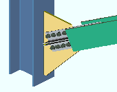
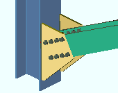
When " Web orientation " is ' Horizontal ' . . .
|
' Web claw angles ' instructs connection design to attempt to connect the brace to the gusset with four angles. The gusset welds to the supporting member. To find an angle, connection design searches the list at Home > Project Settings > Fabricator > Standard Fabricator Connections > Preferred Angle Sizes . If it can't find a suitable angle in that list, it searches the local shape file . |
|
' Flange gussets ' configures connection design to try to create two flange gussets that weld to the supporting member and field bolt to the flanges of the brace. If a supporting column's flange is too narrow, welded clip angles may be used to effectively widen the flange of that column. Click here for an example. |
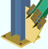
When " Web orientation " is ' Vertical ' . . .
|
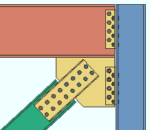
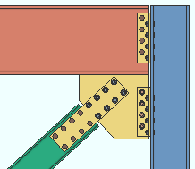
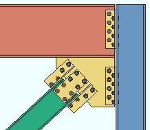
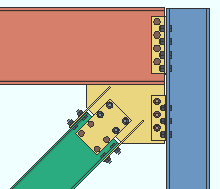
' Standard connection ' instructs connection design to connect the brace to the gusset with flange angles and web connection plates. Additional configuration controls: " Web connection type " and " Flange connection type ." |
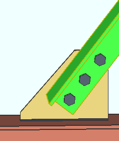
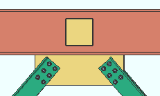
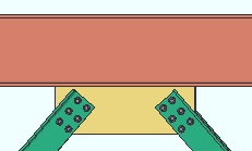
Web connection type: Automatic or None or Web plates or Channels . This " ![]() Connection specifications " option applies when ' Standard connection ' is selected as the " Connection arrangement " for a wide flange vertical brace whose " Web orientation " is ' Vertical '. The option can be found on the Vertical Brace Edit window or at Home > Project Settings > Job > User Defined Connections .
Connection specifications " option applies when ' Standard connection ' is selected as the " Connection arrangement " for a wide flange vertical brace whose " Web orientation " is ' Vertical '. The option can be found on the Vertical Brace Edit window or at Home > Project Settings > Job > User Defined Connections .
|
|
|||||||||
| The vertical brace on the left has a smaller section size and a smaller applied tension load than do the braces in the other two examples. |
' Automatic ' specifies that connection design apply a setup choice ( Home > Project Settings > Job > Design Settings > " Wide flange vertical brace gusset web connection ").
' None ' can get a connection when the " Flange connection type " is set to ' Flange claw angles '. That connection will consist of flange claw angles without a web connection.
' Web plates ' can get a connection when the " Flange connection type " is set to ' Flange claw angles ' or to ' Flange paddle plates ' or to ' None '. The NS and FS web plates connect the web of the web-vertical wide flange vertical brace to the gusset plate.
' Channels ' can get a connection when the " Flange connection type " is set to ' None '. If " Flange connection type " is set to ' Flange claw angles ', connection design fails the connection and emits the failure massage " Incompatible web and flange connection types ." A channel web connection consists of NS and FS channels that connect the web-vertical wide flange vertical brace to the gusset plate.
End connection failure message: WF brace flg is too narrow for connection
End connection failure message: Incompatible web and flange connection types
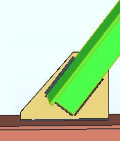
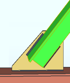
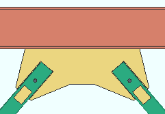
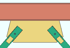
Flange connection type: Automatic or None or Flange claw angles or Flange paddle plates . This " ![]() Connection specifications " option applies when ' Standard connection ' is selected as the " Connection arrangement " for a wide flange vertical brace whose " Web orientation " is ' Vertical '. The option can be found on the Vertical Brace Edit window or at Home > Project Settings > Job > User Defined Connections .
Connection specifications " option applies when ' Standard connection ' is selected as the " Connection arrangement " for a wide flange vertical brace whose " Web orientation " is ' Vertical '. The option can be found on the Vertical Brace Edit window or at Home > Project Settings > Job > User Defined Connections .
|
|
|||||||||
| The left and middle examples have the same " Tension load ." The example on the right has a smaller " Tension load ." |
|
' Flange paddle plates ' can be designed with or without ' Web plates '. |
' Automatic ' specifies that connection design apply the choice made to at Home > Project Settings > Job > Design Settings > " Wide flange vertical brace gusset flange connection ."
' None ' instructs connection design to attempt to design a ' Standard connection ' that does not use claw angles. Web plates and channel web connections can potentially be designed without flange angles.
' Flange claw angles ' with the " Web connection type " set to ' Automatic ' configures connection design to attempt to create a ' Standard connection ' that uses claw angles to connect the wide flange vertical brace's flanges to the gusset plate. The shape of the gusset is adjusted to permit the flange angles to fit. Connection design is able to design web plates with flange angles but cannot design a channel web connection with flange angles. Flange angles can be designed without a web connection.
' Flange paddle plates ' with " Web connection type " set to ' Automatic ' specifies that connection design attempt to design a ' Standard connection ' that uses paddle plates to connect the wide flange vertical brace's flanges to the gusset plate. The shape of the gusset is adjusted to permit the flange angles to fit. Connection design is able to design web plates with flange paddle plates but cannot design a channel web connections with flange paddle plates. Flange paddle plates can be designed without a web connection.
End connection failure message: Incompatible web and flange connection types
End connection failure message: WF brace flg is too narrow for connection
Pipe/tube end-fitting: Welded or Bolted or Paddle plate or Paddle plate (double shear) or Double paddle plate . This " ![]() Connection specifications " option applies when -- under "
Connection specifications " option applies when -- under " ![]() General settings " -- the vertical brace's " Section size " is an HSS or pipe or tube. The option can be found on the Vertical Brace Edit window or at Home > Project Settings > Job > User Defined Connections .
General settings " -- the vertical brace's " Section size " is an HSS or pipe or tube. The option can be found on the Vertical Brace Edit window or at Home > Project Settings > Job > User Defined Connections .
|

|
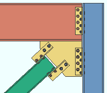
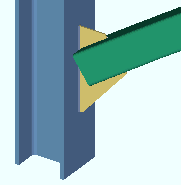
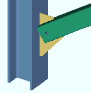
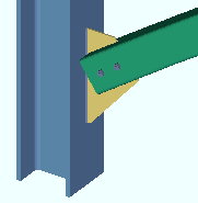
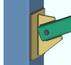
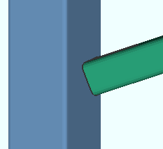
' Welded ' cuts a ' Notch ' in the HSS brace so that it fits around the gusset for field welding. One, two or zero erection field bolts hold the brace into place for field welding. 3D field welds are generated in the model. See: Member Detailing Settings > " Notch length clearance " and " Erection bolts " and Bolt Settings > " HSS welded brace erection bolts ." |
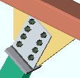
|
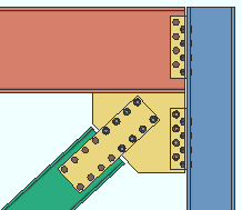
' Bolted ' instructs connection design to create a built-up tee (made of plates) that shop welds to the end of the HSS vertical brace so that the brace can be field bolted to the gusset. |
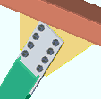
|
' Paddle plate ' configures connection design to ' Notch ' the HSS brace so that the paddle plate can be fitted into the notch and be shop welded to the brace. The paddle plate field bolts to the gusset. |
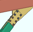
|
' Paddle plate (double shear) ' inserts a paddle plate in the HSS brace. The paddle plate is centered in the notched HSS brace and with respect to the gusset thickness. Connection plates shop bolt to each side of the centered paddle plate and field bolt to both sides of the gusset plate. Click here for an example from the Connection Guide. |
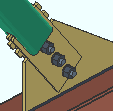
|
' Double paddle plate ' puts paddle plates on both sides of the gusset plate. Spacer plates that are the thickness of the gusset plate are inserted between the paddle plates along the length of the HSS slot. |
'Welded' locks: VBrc to a beam || to a column || to beam & column || shared
'Paddle plate' locks: VBrc to a beam || to a column || to beam & column || shared || to a column & base/cap plate
Reinforcement plate locks: Brace Reinforcement
'Bolted' locks: VBrc to a beam || to a column || to beam & column || shared || to a column & base/cap plate
'Paddle (double shear)' locks: VBrc to a beam || to a column || to beam & column || to a column & base/cap plate
Setup: Total notch width clearance (for ' Welded ' and ' Paddle plate ' and ' Paddle plate (double shear) ')
Setup: HSS double paddle clearance (for ' Double paddle plate ')
Setup: HSS welded brace erection bolts (for ' Welded ')
Advanced Selection: PipeTubeEndFitting
Parametric module: PipeTubeEndFitting
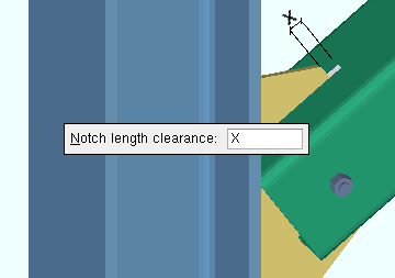
Notch length clearance: The distance (in the primary dimension " Units " or other units ) that the notch extends beyond the gusset plate into the interior of the HSS brace. This option applies when -- here in " ![]() Connection specifications " -- the " Pipe/tube end fitting " is ' Welded ' and -- in "
Connection specifications " -- the " Pipe/tube end fitting " is ' Welded ' and -- in " ![]() General settings " -- the " Section size " for this brace is a HSS rectangular (tube) or HSS round (pipe) section. The option can be found on the Vertical Brace Edit window or at Home > Project Settings > Job > User Defined Connections .
General settings " -- the " Section size " for this brace is a HSS rectangular (tube) or HSS round (pipe) section. The option can be found on the Vertical Brace Edit window or at Home > Project Settings > Job > User Defined Connections .
|
| The " Notch length clearance " (X) for an HSS rectangular vertical brace field welded to the gusset . |
Advanced Selection: NotchLengthClearance
Parametric module: NotchLengthClearance
Erection bolts: Automatic or None or One or Two . This applies when -- here in " ![]() Connection specifications " -- the " Pipe/tube end fitting " is ' Welded ' and -- in "
Connection specifications " -- the " Pipe/tube end fitting " is ' Welded ' and -- in " ![]() General settings " -- the " Section size " for this brace is a HSS rectangular (tube) or HSS round (pipe) section. The option can be found on the Vertical Brace Edit window or at Home > Project Settings > Job > User Defined Connections .
General settings " -- the " Section size " for this brace is a HSS rectangular (tube) or HSS round (pipe) section. The option can be found on the Vertical Brace Edit window or at Home > Project Settings > Job > User Defined Connections .
|
|
|
' Automatic ' specifies that connection design apply a setup choice ( Home > Project Settings > Fabricator > Member Detailing Settings > the " Vertical Braces " tab > " HSS erection bolts ").
' None ' instructs connection design to not generate an erection bolt or the holes that the bolt goes into.
' One ' instructs connection design to createa field erection bolt along with holes for inserting the bolt into.
' Two ' instructs connection design to create two field erection bolts along with holes for inserting the bolts into.
Member Detailing Settings: " HSS erection bolts " and " Hole type for HSS erection bolts "
Bolt Settings: " HSS welded brace erection bolts "
Advanced Selection: ErectionBolts
Parametric module: ErectionBolts
Spacing for two erection bolts: Hole spacing along brace (vbrc to beam)
Spacing for two erection bolts: Hole spacing along brace (vbrc to columns)
Spacing for two erection bolts: Hole spacing along brace (vbrc to beam &column)
Spacing for two erection bolts: Hole spacing along brace (vbrc, 2 point, to a beam)
Spacing for two erection bolts: Hole spacing along brace (vbrc, 2 point, to a column)
Clip end operation: Automatic or Yes or No . This " ![]() Connection specifications " option can apply to a vertical brace whose " Section size " is a W tee (WT), a channel (C or MC), or an angle (L). If the connection is for a " Seismic brace ," the gusset plate will always be clipped, regardless of the choice made here. The option can be found on the Vertical Brace Edit window or at Home > Project Settings > Job > User Defined Connections .
Connection specifications " option can apply to a vertical brace whose " Section size " is a W tee (WT), a channel (C or MC), or an angle (L). If the connection is for a " Seismic brace ," the gusset plate will always be clipped, regardless of the choice made here. The option can be found on the Vertical Brace Edit window or at Home > Project Settings > Job > User Defined Connections .
|
|||||||
|
|||||||
|
' Automatic ' specifies that connection design apply a setup choice ( Home > Project Settings > Fabricator > Standard Fabricator Connections > Standard Gusset Plate Settings > " Clip end operation on W tee brace gusset plates " or " Clip end operation on channel brace gusset plates " or " Clip end operation on angle brace gusset plates ").
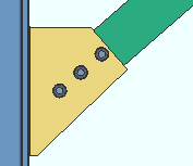
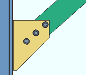
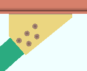
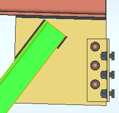
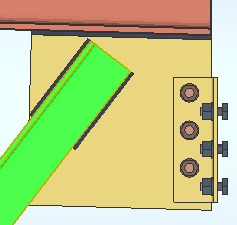
' Yes ' instructs connection design to perform a ' Clip ' operation on the gusset plate to create an edge perpendicular to the vertical brace. In the table below, the names of leaves containing connection design locks are listed in the "Yes" column.
' No ' configures connection design to not perform the ' Clip ' operation, and the gusset comes to a point over the vertical brace. In the table below, the names of leaves containing connection design locks are listed in the "No" column.
Connection design locks:
|
' Yes '
(WT, C, L) |
' No '
(W tee, channel) |
' No '
(angle) |
|
| to a beam | Gusset One Member | Gusset One Member Square | Gusset One Member Square |
| to a column | Gusset One Member | Gusset One Member Square | Gusset One Member Square |
| to a beam & col | Gusset Beam Column | Gusset Beam Column Square | Gusset Beam Column Square |
| shared gusset | Gusset 2 Point | Gusset 2 Point Square | Gusset 2 Point Square |
| to column & plate | Gusset Column Cap | Gusset Column Cap Square | Gusset Column Cap Square |
End connection failure message: Shared brace Clip end-operatiion settings must match
Angle end fitting: Bolted or Welded . A vertical brace can be welded to its gusset plate when -- in " ![]() General settings " -- its " Section size " is an angle and " Double material " is either not checked (
General settings " -- its " Section size " is an angle and " Double material " is either not checked ( ![]() ) or checked (
) or checked ( ![]() ). If "
). If " ![]() Double material " is checked, the " Configuration " must be ' Back to back '. This "
Double material " is checked, the " Configuration " must be ' Back to back '. This " ![]() Connection specifications " option can be found on the Vertical Brace Edit window or at Home > Project Settings > Job > User Defined Connections .
Connection specifications " option can be found on the Vertical Brace Edit window or at Home > Project Settings > Job > User Defined Connections .
|
|
' Bolted ' bolts the angle(s) to the gusset plate.
' Welded ' welds the angle(s) to the gusset plate. The "
Connection specifications " options " Include end welds " and " Balanced welds " configure the weld pattern.
Include end welds: Automatic or Yes or No . This " ![]() Connection specifications " option applies when " Angle end fitting " is set to ' Welded '. The option can be found on the Vertical Brace Edit window or at Home > Project Settings > Job > User Defined Connections .
Connection specifications " option applies when " Angle end fitting " is set to ' Welded '. The option can be found on the Vertical Brace Edit window or at Home > Project Settings > Job > User Defined Connections .
|
|
' Automatic ' applies a setup choice ( Home > Project Settings > Fabricator > Detailing > Member Detailing Settings > the " Vertical Braces " section > " Welded angle end weld ").
' Yes ' welds three sides of the angle to the gusset plate. One weld is placed on the end of the angle. The other two welds run along the length of the angle.
' No ' welds two sides of the angle to the gusset plate. Both welds are along the length of the angle. The end weld is not included.
Balanced welds: Automatic or Yes or No . This " ![]() Connection specifications " option applies when " Angle end fitting " is set to ' Welded '. The option can be found on the Vertical Brace Edit window or at Home > Project Settings > Job > User Defined Connections .
Connection specifications " option applies when " Angle end fitting " is set to ' Welded '. The option can be found on the Vertical Brace Edit window or at Home > Project Settings > Job > User Defined Connections .
|
|
' Automatic ' applies a setup choice ( Home > Project Settings > Fabricator > Detailing > Member Detailing Settings > the " Vertical Braces " section > " Welded angle balanced welds ").
' Yes ' instructs the program to design a weld group that is balanced. A weld group is balanced when its center of resistance aligns with the center of force.
' No ' welds the angle to the gusset using welds of equal length along the length of the brace.
Use HSS column reinforcement plate: Automatic or Yes or No . This " ![]() Connection specifications " option applies when a vertical brace with a gusset plate frames to an HSS rectangular (or tube) column with a thin wall.
Connection specifications " option applies when a vertical brace with a gusset plate frames to an HSS rectangular (or tube) column with a thin wall.
|
|
|
' Automatic ' specifies that connection design apply a setup choice ( Home > Project Settings > Job > Plate Design Settings > " Use HSS column reinforcement plate ").
' Yes ' instructs connection design to weld a reinforcement plate to the face of the HSS rectangular column if such a reinforcement plate is needed to prevent a connection design failure. The vertical brace gusset plate welds to the reinforcement plate.
' No ' configures connection design to not create an HSS column reinforcement plate. The connection may fail with the message " HSS wall strength fails ."
Plate Design Settings: Use HSS column reinforcement plate ( Home > Project Settings > Job > Plate Design Settings )
End connection failure message: HSS wall strength fails
End connection failure message: Braces must have same HSS column reinforcement type
Connection design locks: "Column Reinf Plate " ( Vertical Brace window)
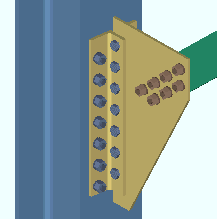
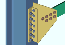
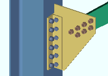
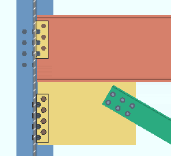
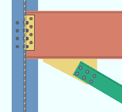
Gusset to supporting member: Automatic (uses setup choice) or Welded (shop welded) or Clip angle (' Bolted ' or ' Welded '). This " ![]() Connection specifications " option applies in the following framing situations:
Connection specifications " option applies in the following framing situations:
| ' Welded ' | ' Clip angle ' | |
| Case 1 : vertical brace to beam only |
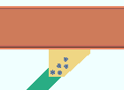
|
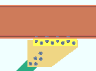
|
| Case 2 : vertical brace to column only |

|

|
| Case 3 : beam on a vbrc to beam & column when a clip angle bolts to the column |
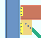
|
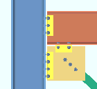
|
| Case 4 : vertical brace to a wide flange vertical brace |

|

|
Special cases: If a member is not wide enough for the clip angles, connection design welds the gusset plate directly to the support. A vertical brace to a column and cap plate is always welded (regardless of the selection made here). For a vertical brace to a beam and column, any beam-to-column connection other than a clip angle causes the gusset to be welded to the beam. For a wide flange vertical brace to a wide flange vertical brace, connection design always uses a clip angle. For 3 point braces , ' Welded ' is the only option that gets a connection.
Advanced Selection: GussetToSupportingMember
Parametric module: GussetToSupportingMember
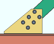
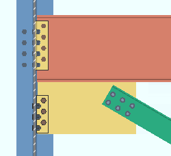
Gusset to beam clips: Match column clip or From setup/conn spec . This " ![]() Connection specifications " option applies when ' Clip angle ' is selected for " Gusset to supporting member " and the vertical brace frames to a beam and column. In such a case, connection design creates the clip angle using the same angle, hole size, bolt size, spacing, etc. as the clip angle on the beam. The option can be found on the Vertical Brace Edit window or at Home > Project Settings > Job > User Defined Connections .
Connection specifications " option applies when ' Clip angle ' is selected for " Gusset to supporting member " and the vertical brace frames to a beam and column. In such a case, connection design creates the clip angle using the same angle, hole size, bolt size, spacing, etc. as the clip angle on the beam. The option can be found on the Vertical Brace Edit window or at Home > Project Settings > Job > User Defined Connections .
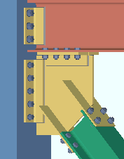
|
A vertical brace to a beam and column. |
' Match column clip ' instructs connection design to attempt to bolt the gusset to the beam using the same clip angle settings that are applied to the clip angle that bolts the gusset to the column.
' From setup/conn spec ' instructs connection design to use the " Clip angle size " and other settings that are set here, in "
Connection specifications ." If those options are set to ' Automatic ', connection design uses the appropriate choices made to Home > Project Settings > Fabricator > Member Detailing Settings > the " Vertical Braces " section. Also, if " Bolt type " or " Bolt diameter " are set to "
Auto " here, in the "
Connection specifications " section, connection design uses the appropriate choices made at Home > Project Settings > Job > Bolt Settings > the " Vertical brace gusset to supporting " section.
Advanced Selection: GussetToBeamClips
Parametric module: GussetToBeamClips
Gusset to clip connection: Automatic or Welded or Bolted . This " ![]() Connection specifications " option sets the method for attaching the clip angle to the gusset plate when ' Clip angle ' is selected for " Gusset to supporting member ." The option can be found on the Vertical Brace Edit window or at Home > Project Settings > Job > User Defined Connections .
Connection specifications " option sets the method for attaching the clip angle to the gusset plate when ' Clip angle ' is selected for " Gusset to supporting member ." The option can be found on the Vertical Brace Edit window or at Home > Project Settings > Job > User Defined Connections .
|
|
' Automatic ' specifies that connection design apply a setup choice ( Home > Project Settings > Job > Member Detailing Settings > the " Vertical Braces " section > " Gusset to clip connection ").
' Welded ' instructs connection design to shop weld the clip angle to the gusset plate.
' Bolted ' configures connection design to, where connection failure can be avoided, shop bolt the clip angle to the gusset plate and leave a half-inch clearance (13 mm) between the gusset and the face of the supporting member. Connection design may change the connection to welded instead of failing the connection.
Connection design locks: "
NS/FS Clip Conn2 " (vbrc to beam) "
NS/FS Clip Conn2 " (vbrc to column) "
NS/FS Clip Conn2 " (vbrc to bm & col)
Advanced Selection: GussetToClipConnection
Parametric module: GussetToClipConnection
Clip angle size: ![]() Auto or user-entered . This "
Auto or user-entered . This " ![]() Connection specifications " option sets the angle material to be used for both the near side and far side clip angles.
Connection specifications " option sets the angle material to be used for both the near side and far side clip angles.
'
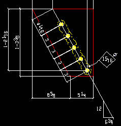
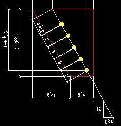
Auto (checked)' instructs connection design to apply a setup choice ( Home > Project Settings > Fabricator > Member Detailing Settings > " Vertical Braces " section > " Clip angle size "). Connection design checks the leg, outstanding leg and thickness to see if the angle works. If that angle doesn't work, connection design tries to find an angle that will work by searching a setup list ( Home > Project Settings > Fabricator > Standard Fabricator Connections > Preferred Angle Sizes ). If none of the angles in that list work, connection design looks for an angle in the local shape file . If no angle works, the " Gusset to clip connection " is changed to ' Welded '.
'
Auto (not checked)' lets you enter the section size. The angle you enter here must exist in the local shape file, or validation does not accept your entry. To enter a section size, you can type in the section size that you want (e.g., ' L4x3x5/16 '), or you can press the "file cabinet" browse button (
) and double-click any section that is on the list of available angles in the local shape file .
Advanced Selection: ClipAngleSizeAuto
Advanced Selection: ClipAngleSizeIndex
Parametric module: ClipAngleSizeAuto
Parametric module: ClipAngleSizeIndex
Attach long leg to: Automatic or Supported or Supporting . This " ![]() Connection specifications " option can be found on the Vertical Brace Edit window or at Home > Project Settings > Job > User Defined Connections .
Connection specifications " option can be found on the Vertical Brace Edit window or at Home > Project Settings > Job > User Defined Connections .
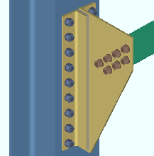
|
In this example, " Attach long leg to " is set to ' Supporting '. The long leg of each of the gusset clip angles bolts to the column. |
' Automatic ' instructs connection design to apply a setup choice ( Home > Project Settings > Fabricator > Member Detailing Settings > " Vertical Braces " section > " Attach long leg to ").
' Supported ' fastens the long leg of the clip angle to the gusset plate.
' Supporting ' fastens the long leg of the clip angle to the supporting beam or column or wide flange vertical brace.
Advanced Selection: AttachLongLegTo
Parametric module: AttachLongLegTo
Hole type supported: ![]() Auto or Standard round or Short slot or Long slot or Oversized or User slot #1 or User slot #2 . The hole type selected here, together with the "
Auto or Standard round or Short slot or Long slot or Oversized or User slot #1 or User slot #2 . The hole type selected here, together with the " ![]() Connection specifications " option " Bolt diameter ," set the diameter of holes for shop bolting the clip angle to the vertical brace gusset plate.
Connection specifications " option " Bolt diameter ," set the diameter of holes for shop bolting the clip angle to the vertical brace gusset plate.
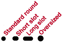
'
Auto ( checked )' instructs connection design to apply a setup choice ( Home > Project Settings > Fabricator > Member Detailing Settings > " Vertical Braces " section > " Hole type supported ").
'
Auto ( not checked )' lets you select any of the above-listed hole types from the menu (
).
Advanced Selection: HoleTypeSupportedAuto
Advanced Selection: HoleTypeSupported
Parametric module: HoleTypeSupportedAuto
Parametric module: HoleTypeSupported
Hole type supporting: ![]() Auto or Standard round or Short slot or Long slot or Oversized or User slot #1 or User slot #2 . The hole type selected here, together with the "
Auto or Standard round or Short slot or Long slot or Oversized or User slot #1 or User slot #2 . The hole type selected here, together with the " ![]() Connection specifications " option " Bolt diameter ," set the diameter of holes for field bolting the outstanding leg of the angle to the supporting beam, column or wide flange vertical brace.
Connection specifications " option " Bolt diameter ," set the diameter of holes for field bolting the outstanding leg of the angle to the supporting beam, column or wide flange vertical brace.

'
Auto ( checked ) ' instructs connection design to apply a setup choice ( Home > Project Settings > Fabricator > Member Detailing Settings > " Vertical Braces " section > " Hole type supporting ").
'
Auto ( not checked )' lets you select any of the above-listed hole types from the list box (
).
Advanced Selection: HoleTypeSupportingAuto
Advanced Selection: HoleTypeSupporting
Parametric module: HoleTypeSupportingAuto
Parametric module: HoleTypeSupporting
Bolt type: ![]() Auto or
Auto or ![]() Auto . This "
Auto . This " ![]() Connection specifications " option sets the bolt type in both legs of the clip angle that fastens the gusset to the supporting member.
Connection specifications " option sets the bolt type in both legs of the clip angle that fastens the gusset to the supporting member.
'
Auto (checked) ' instructs connection design to apply a setup choice ( Home > Project Settings > Job > Bolt Settings > " Bolt type " under " Vertical brace gusset to supporting ").
'
Auto (not checked) ' lets you select a bolt type from the list box (
). Choices in the list box come from Home > Project Settings > Job > Bolt Settings .
Bolt diameter: ![]() Auto or
Auto or ![]() Auto . This "
Auto . This " ![]() Connection specifications " option sets the diameter of bolts in both legs of the clip angle. The bolt diameter entered here, together with the " Hole type supported " or " Hole type supporting ," set the diameter of holes the bolts go into.
Connection specifications " option sets the diameter of bolts in both legs of the clip angle. The bolt diameter entered here, together with the " Hole type supported " or " Hole type supporting ," set the diameter of holes the bolts go into.
| diameter |
|
'
Auto (checked)' instructs connection design to apply a setup choice ( Home > Project Settings > Job > Bolt Settings > " Bolt diameter " [for vertical brace to supporting]).
'
Auto (not checked) ' lets you type in any diameter (inches or mm) or select a bolt diameter from the combo box (
). Diameters listed in the combo box come from Home > Project Settings > Job > Bolt Settings > " Available bolts ."
Setup options tied to bolt diameter: " Vertical edge distance at ends " ( Home > Project Settings > Fabricator > Standard Fabricator Connections > Clip Angle Settings ), " Allow reduced edge distance for 7/8" and 1" bolts " ( Home > Project Settings > Job > Member Detailing Settings > " Vertical Braces " section).
Advanced Selection: BoltDiameterAuto
Advanced Selection: BoltDiameter
Parametric module: BoltDiameterAuto
Parametric module: BoltDiameter
Stagger bolts: Automatic or Yes or No . This " ![]() Connection specifications " option applies to the selected " Clip angle size " as long as the " Gage on supporting member " and " Gage on supported member " are also applied. Also, the " Gusset to clip connection " must be ' Bolted ' (or ' Automatic ' with bolted as the setup choice). The " Stagger bolts " option can be found on the Vertical Brace Edit window or at Home > Project Settings > Job > User Defined Connections .
Connection specifications " option applies to the selected " Clip angle size " as long as the " Gage on supporting member " and " Gage on supported member " are also applied. Also, the " Gusset to clip connection " must be ' Bolted ' (or ' Automatic ' with bolted as the setup choice). The " Stagger bolts " option can be found on the Vertical Brace Edit window or at Home > Project Settings > Job > User Defined Connections .
|
|
' Automatic ' specifies that connection design apply a setup choice ( Home > Project Settings > Fabricator > Detailing > Member Detailing Settings > " Vertical Braces " section > " Stagger bolts ").
' Yes ' instructs connection design to stagger the bolts in the clip angle.
' No ' configures connection design to not stagger the bolts.
Gage on supporting: ![]() Auto or
Auto or ![]() Auto . This "
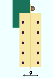
Auto . This " ![]() Connection specifications " option sets the center-to-center dimension between columns of holes on the outstanding legs of the clip angles. Connection design attempts to apply this gage even if it uses a different " Clip angle size " than that which is selected above.
Connection specifications " option sets the center-to-center dimension between columns of holes on the outstanding legs of the clip angles. Connection design attempts to apply this gage even if it uses a different " Clip angle size " than that which is selected above.
|
g = gage on supporting member. The supporting member in this example is a column (not shown). Connection design uses double clip angles for vertical braces to the supporting member. This does not apply to the clip angle to the column for a vertical brace to a beam and column. |
'
Auto (checked) ' specifies that connection design use a setup choice ( Home > Project Settings > Fabricator > Member Detailing Settings > " Vertical Braces " section > " Gage on supporting member ").
'
Auto (not checked) ' lets you type in the center-to-center dimension (in the primary dimension " Units " or other units ).
If the gage entered here doesn't work -- for example, because ' 0 ' is entered -- connection design uses the gage in the local shape file for the supporting member (e.g. " Flange gage " for a wide flange column). If that gage doesn't work, connection design uses the angle gage .
UFM special case design: Automatic or No special case or Special case 2 or Special case 3 . This " ![]() Connection specifications " option can be found on the Vertical Brace Edit window or at Home > Project Settings > Job > User Defined Connections .
Connection specifications " option can be found on the Vertical Brace Edit window or at Home > Project Settings > Job > User Defined Connections .
|
|
|
|
|
' Automatic ' specifies that connection design apply a setup choice ( Home > Project Settings > Job > Design Settings > " UFM special case design ").
' No special case ' instructs connection design to distribute the brace's vertical force to the beam as well as to the gusset-to-column connection. This minimizes the size of the gusset plate, but may result in the beam connection failing under heavily loaded conditions. See The Uniform Force Method , AISC 14th Edition , p 13-3.
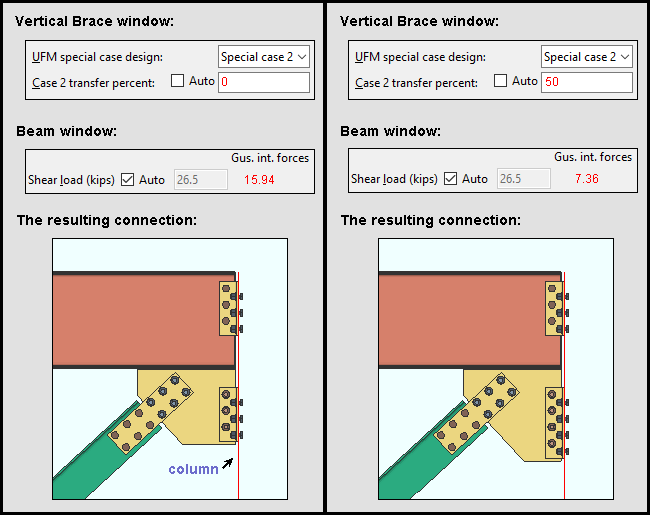
' Special case 2 ' instructs connection design to distribute the brace's vertical force to the gusset-to-column connection instead of to the beam. As a result, the beam's vertical reaction is not increased. This may prevent the beam connection from failing if the beam is highly loaded, but also may add rows to the column connection and thus cause the gusset plate to be larger. See Special Case 2, Minimizing Shear in the Beam-to-Column Connection , AISC 14th Edition , p 13-7. The " Case 2 transfer percent " option (below) lets you specify the percentage of the brace's vertical force that you want distributed to the gusset-to-column connection.
' Special case 3 ' configures connection design to connect the vertical brace to the beam, but not to the column. See Special Case 3, No Gusset-to-Column Web Connection , AISC 14th Edition , p 13-7. Be aware that special case 3 does not apply to gusset-to-column flange connections. For gusset-to-column flange connections, the connection is designed as if ' No special case ' has been selected. Click here for an example (Example 2) from the Connection Guide.
Case 2 transfer percent : ' ![]() Auto ' or '
Auto ' or ' ![]() Auto ' . This "
Auto ' . This " ![]() Connection specifications " option applies when ' Special case 2 ' is selected for " UFM special case design ."
Connection specifications " option applies when ' Special case 2 ' is selected for " UFM special case design ."
'
Auto (checked) ' transfers 100% of the gusset interface " Shear " force to the gusset-to-column connection.
'
Auto (not checked)' lets you enter the percentage of vertical gusset interface forces that you want to be transferred from the beam to the gusset-to-column connection. An entry of ' 100 ' percent would result in an entry of 0.0 to " Gusset Interface Forces " in the " Shear " row on the Beam Edit window since the entire shear component of the forces from the brace would be transferred to the gusset-to-column interface. An entry of ' 50 ' percent would result in half of the force being transferred to the gusset-column connection. An entry of ' 0 ' percent would result in all gusset interface forces from the brace being applied to the beam, thus giving you the same result as you would get by choosing ' No special case ' for " UFM special case design ."
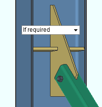
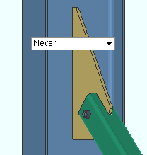
Check supporting member for web stress: If required or Never . The " Supporting member web stress " is reported as a " ![]() Left/Right end limit state " when a vertical brace gusset (single, 2 point or 3 point) is welded to the web of the supporting column or beam. This "
Left/Right end limit state " when a vertical brace gusset (single, 2 point or 3 point) is welded to the web of the supporting column or beam. This " ![]() Connection specifications " option controls whether or not web stress is checked by connection design when it designs a gusset plate. The option can be found on the Vertical Brace Edit window or at Home > Project Settings > Job > Connections > User Defined Connections .
Connection specifications " option controls whether or not web stress is checked by connection design when it designs a gusset plate. The option can be found on the Vertical Brace Edit window or at Home > Project Settings > Job > Connections > User Defined Connections .
|
||
| Connection design may add a web stiffener when ' If required ' is selected. For 2-point or 3-point gusset plates, two stiffeners may be added. |
' If required ' results in design calculations 175 or 359 being a potential cause of connection failure. To prevent such a failure, web stiffeners may be designed with lockable settings shown in the "
Stiffener Plate " leaf. The " Maximum web stiffener thickness " for these stiffeners can be set in Home > Project Settings > Fabricator > Detailing > Member Detailing Settings > the " Vertical Braces " section. The stiffeners can be designed for 2-point, 3-point or single vertical brace gusset plates.
' Never ' results in calculations 175 or 359 still being performed, where applicable, but not ever causing the connection to fail. In the Connection Design Calculations or Expanded Connection Design Calculations , the results of the check is reported with a parenthetical, for-information-only note such as " (For information only, brace force that produces local column web stress of .9Fy (175) 33.0 kips ) "
End connection failure message: Supporting web/flg overstressed by axial load .
Check supporting member for web crippling: If required or For supporting column or For supporting beam or never . This " ![]() Connection specifications " option can be found on the Vertical Brace Edit window or at Home > Project Settings > Job > User Defined Connections .
Connection specifications " option can be found on the Vertical Brace Edit window or at Home > Project Settings > Job > User Defined Connections .
' If required ' results in design calculations 361 being a potential cause of connection failure when applicable.
' For supporting column ' results in calculation 361 being a potential causes of connection failure for the supporting column.
' For supporting beam ' results in calculation 361 being a potential causes of connection failure for the supporting beam.
' Never ' results in load calculations 361 still being performed, where applicable, but not ever resulting in a connection design failure. In the Connection Design Calculations or Expanded Connection Design Calculations , the results of the check are reported with a parenthetical, for-information-only note.
Check supporting member for web shear: This " ![]() Connection specifications " option applies to 2-point vertical braces to a beam or column. The option can be found on the Vertical Brace Edit window or at Home > Project Settings > Job > User Defined Connections . The option has no effect on a " Seismic brace " since the supporting beam or column for 2-point seismic braces is always checked for web shear, regardless of the choice made here.
Connection specifications " option applies to 2-point vertical braces to a beam or column. The option can be found on the Vertical Brace Edit window or at Home > Project Settings > Job > User Defined Connections . The option has no effect on a " Seismic brace " since the supporting beam or column for 2-point seismic braces is always checked for web shear, regardless of the choice made here.
|
||
| Connection design may add beam web doublers for a 2-point vertical brace when ' If required ' is selected. |
' If required ' results in design calculations 442 potentially creating web doublers to strengthen the supporting member's web. That supporting member can be a beam or a column. Connection design locks are maintained in a leaf named "
Web Doublers " that can be found on the Vertical Brace Edit window. By default, the doublers are placed on both sides of the beam's or column's web, but this can be changed by adjusting the " Plate location " in the leaf.
' Never ' results in load calculation 442 not being used to check for web shear.
Check supporting member for flange bending: If required or For supporting column or For supporting beam or never . " Beam flange bending " and/or " Column flange bending " are reported as a " ![]() Left/Right end limit state " for a web-horizontal wide flange vertical brace to a beam and column. This "
Left/Right end limit state " for a web-horizontal wide flange vertical brace to a beam and column. This " ![]() Connection specifications " option affects whether or not that limit state is incorporated as a check within connection design that can potentially cause the vertical brace connection to fail.
Connection specifications " option affects whether or not that limit state is incorporated as a check within connection design that can potentially cause the vertical brace connection to fail.
' If required ' makes design calculation 250 a potential cause of connection failure when applicable.
' For supporting column ' makes calculation 250 a potential causes of connection failure for the supporting column.
' For supporting beam ' makes calculation 250 a potential causes of connection failure for the supporting beam.
' Never ' results in load calculations 250 still being performed, where applicable, but not ever resulting in a connection design failure. In the Connection Design Calculations or Expanded Connection Design Calculations , the results of the check are reported with a parenthetical, for-information-only note such as " For information only --- Beam flange local bending (250) 1053.8 kips ."
AISC seismic 1st ed. 2pt gussets: Automatic or Yes or No . This " ![]() Connection specifications " option applies to the design of 2-point vertical brace gusset plates when " Seismic brace " is set to ' Yes ' (or to ' Automatic ' with "
Connection specifications " option applies to the design of 2-point vertical brace gusset plates when " Seismic brace " is set to ' Yes ' (or to ' Automatic ' with " ![]() Seismic vertical brace gusset design " checked on). The option can be found on the Vertical Brace Edit window or at Home > Project Settings > Job > User Defined Connections .
Seismic vertical brace gusset design " checked on). The option can be found on the Vertical Brace Edit window or at Home > Project Settings > Job > User Defined Connections .
|
|
||
| The 1st edition AISC seismic design manual specifies more cuts for 2-point gusset plates than does later editions of that same manual. |
' Automatic ' specifies that connection design apply a setup choice ( Home > Project Settings > Job > Design Settings > " Use AISC seismic design 1st edition gusset geometry for 2 point gusset design ").
' Yes ' instructs connection design to create a 2-point seismic gusset plate based on the 1st edition of the AISC seismic design manual. Additional locks for adding stiffeners are provided in "
Gusset 2 Point " (HSS) or etc.
' No ' configures connection design to create a 2-point seismic gusset plate based on the 2nd edition of the AISC seismic design manual.
