 Save Standard Detail
Select an area of your current drawing to be copied and saved as a job standard detail.
- Step-By-Step
- Tips and Tricks
- Related Tools
1. Preselect multiple items to enable the Multiple Objects contextual page and click the Save Standard Detail icon found in the Standards section.
Alternative: Invoke Save Standard Detail using the Find Tool by searching the command name and clicking the icon, which is pictured above.
Learn more about alternative methods for launching commands.
2. The status line prompts you to locate the area of clipping boundaries. The Locate-Pan-Return mouse bindings become active, and the Locate contextual page becomes active. Hold down the left mouse button (Locate) and draw a box around the selected items you want to save as a job standard detail. When polygons, bolts, holes, and clouds are only partially inside the clipping boundaries, they will be clipped (removed) from the job standard detail.
Alternative 1: If you did not preselect multiple items in step 1, the status line prompts you to select items to save. Draw an area box around the items you want to save as a job standard detail. You can also select or add more items to your selection by holding Shift and using left-click (Select +). You can remove items from your selection by holding down Ctrl and using left-click (Select -). When you are done selecting items, press Enter or right-click (Menu) and select OK. Then follow step 2.
Alternative 2: Press Esc or right-click (Return) to cancel the command. Right-click (Menu) and select Cancel if you are in the selection phase of Alternative 1.
3. The status line prompts you to locate a reference point. The reference point is used as the insertion point for the job standard detail when it is imported into other drawings using Add Standard Detail. Place your mouse pointer so the point location target snaps to where you want the reference point, then left-click (Locate).
Tip: If you later find that you want to relocate this reference point, you can open the job standard detail and use Verify Reference Point.
Alternative: Press Esc or right-click (Return) to cancel the command.
4. The Area Save window opens. See below for more information about its options. When you are done using this window, click the OK button to save the job standard detail.
Alternative: Press the Cancel button or press Esc to cancel the command.
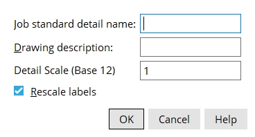
Job standard detail name: The name (up to 61 characters) you want to appear on the selection list of job standard details.
Detail description: The description (up to 22 characters) you want to appear as the Material description in the Drawing Data Panel for the job standard detail you are creating.
Detail Scale (Base 12 or 10): The default scale shown here is the scale of your current drawing. Base 12 indicates the scale is in imperial units (X inch = one foot). Base 10 indicates the scale is in metric units (X mm = 10 mm). Changing the scale causes all graphic elements (except labels if the box for Rescale labels is checked) to automatically be re-sized.
Rescale labels: Applies when a new Detail Scale has been entered. If this box
is checked, labels on the job standard detail are re-sized per the new Detail Scale that was entered above. If the box
is not checked, the labels retain their current scale.

