Graphics found in Modeling Erection Views (topics)
- 3D erection views created in Modeling can be Detailed to create erection view drawings. Many of the 3D graphics shown in Modeling can also be shown on the 2D drawings.
| Area box ( |
Member ends |
| Assemblies (link is to another page) | Member numbers |
| Bolts, 3D | Moment connection (stick form) |
| CNC marks (solids form) | Member orientation indicators (stick) |
| Connection components | Notes ( |
| Construction lines/circles | Noticed points & temporary construction lines |
| Cranes and crane placements | Origin reference point |
| Cross section, wide flange (stick form) | Piecemarks |
| Cross section, pipe (stick form) | Point location target |
| Cross section, channel (stick form) | Reference drawings in Modeling |
| Custom components ( |
Reference model member |
| Custom members | Section size |
| Embed assemblies | Shear plates side indicator (stick form) |
| Grid lines (straight grid lines are views) ( |
Terrain |
| Holes | UCS axes |
| Layout nodes | Welds, 3D |
| Materials (link is to another page) | Work lines (member lines) |
| Members | Work plane highlighting |
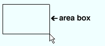
Area box
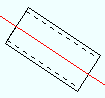
- An area box can be made to appear in Modeling when you hold down the left mouse button in Select Items mode and drag your mouse pointer (
 ) diagonally across the screen. Items within the periphery of the area box are selected or deselected depending on whether you have no key pressed ( Select ) or the Shift key pressed ( Select+ ) or the Ctrl key pressed ( Select- ) or the Ctrl + Shift keys pressed ( Toggle ). An area box can also be used for selection in the Drawing Editor .
|
An area box being drawn from left to right. |
|
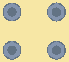
3D bolts
Bolts can be made visible in Modeling erection views when members are displayed in one of the three solid forms .
|
3D bolts can now be added, by users, as bolts or as material bolts . Process and Create Solids automatically generates only bolts, not material bolts. |
Shop and field bolts: By default, when the " Default bolt class " (in Bolt Settings setup) is set to ' Automatic ', shop bolts fasten materials that are parts of the same member, whereas field bolts fasten materials that are parts of different members. This default bolt behavior can be overridden by changing the bolt " Class " on the Bolt Edit window. ' Field ' bolts and ' Shop ' bolts may be displayed in different colors based at Home > Project Settings > Job > Member, Material, Bolt and Weld Colors . Field bolts are not drawn on member details -- only the holes they go into are drawn. Shop bolts are drawn on member details.
Tools for bolts: Bolt Mode , Add Bolts , Add Bolts to Single Ply , Edit Bolt , Erase Bolts , Check Bolt . Add Bolts to Single Ply and Edit Bolt open the Bolt Edit window. The generic Delete tool can be used to erase bolts. Double-click in Select Items mode can be used to edit bolts when either the ' Bolts ' selection filter or ' Default ' is selected. Setting a " Model completed " date on a member prevents bolts from being altered on that member. Material bolts can be added using Add Material or Add Miscellaneous Member . Bolts can be copied using Model > Material > Copy .
Bolts in assemblies: You can save welds and bolts as well as materials when you Model > Assembly Save or in the Assembly Editor ; However, for bolts, if the assembly is going to be added to a main material of a non-miscellaneous member, you may prefer to just let Process and Create Solids match the holes in the assembly to the main material as described in the next paragraph.
For adding bolts to the main material on beams, columns, braces, girts or purlins, you can add a material that has holes in it so that the material's surface is face-to-face with the member main material, then Process and Create Solids . The Process and Create Solids program will automatically match holes and generate bolts through the holes in the material and the matched holes in the member main material. This does not work for miscellaneous members.
Display of bolts: Bolts are displayed only when the members they are associated with are in one of the three solid forms . The display of bolts can be turned on/off using the " Bolts " check box in Display Options . When you zoom out in a view, bolt display is turned off per User and Site Options > Modeling > " Level of detail ."
Setup of bolts: Standard Fabricator Connections lets you set up hole spacing for various system connections . The Bolt Specifications lets you define what types of bolts are selectable on the 3D Bolt Edit window. Home > Project Settings > Job > Bolt Settings and Home > Project Settings > Job > Washer Settings set what kinds of bolts and washers are automatically used to fasten connecting materials when system connections are generated. The default non-moment " Bolt diameter " sets the standard hole size for your current Job. Default Member colors lets you set up different display colors for field bolts and shop bolts . Other setup options include: " All imperial bolt lengths in 1/2 inch increments ," " Add washers to prevent shank-out when needed ," Nut and Washer Schedule (for assigning steel grades to individual nuts and washers).
Status Display: Bolt status
Display Options: Bolts
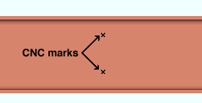
CNC mark
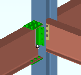
Connection components
|
When the selection filter is ' Connection Components ' or ' Default ' or ' All ', clicking a connection material selects the entire component. Double-clicking a connection material opens the Connection Component Edit window. |
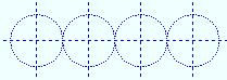
Construction lines/circles
- Construction lines and construction circles are graphic objects that appear in both the Drawing Editor and Modeling . They are dashed lines or dashed circles or dashed ellipses that may be blue or other colors. Finite construction lines are available in Modeling , where they can be added using Finite Construction Line Add .
|
Construction circles can be perfect circles (as shown) or ellipses. |
Display Options: Construction lines
Display Options: Construction circles
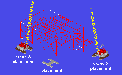
Cranes & crane placements
Licensing:
- Cranes and their placements may be present in your model. Model > Crane options require a license. Without that license, cranes are not functional in SDS2.
|
Each crawler crane in this example has at least one placement. The crane on the left has a second placement. You could move that crane to its second placement if you chose to -- see " Change placement ." Doing so would not affect Lift Information -- it would affect appearances only. |
|
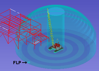
In this example, a crane placement is selected. The "dome" around the crane placement represents the reach of the crane's boom. The center cylinder is the no-lift zone around the crane. The alternating dark and light bands are each 10 ft wide. The furthest laydown point ( |
Adding cranes in Modeling :
Other crane tools:
Display Options: Cranes and Crane Placements
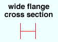
A wide flange cross section , when displayed in stick form , appears as shown below.
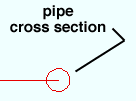
A pipe cross section , when displayed in stick form , appears as shown below.
A channel cross section , when displayed in stick form , appears as shown below.

Custom components can be added to members in Modeling , using Components Add . To distinguish these components from connection components , this documentation refers to them as custom components. The following YouTube video provides a nice overview: Customers' Classroom: SDS2 Components 101 ( ![]() ).
).
|
How they differ: Connection components are member end connections that are generated connection design . Custom components are generated using Python script plugins. |
|
|
This example of an HSS Cap Plates custom component is a " Component " of the vertical brace that it was added to. That means that it can be edited on the Vertical Brace Edit window. HSS Cap Plates custom components can be added to any non-miscellaneous HSS member, not just to vertical braces. A custom component can also be edited on its own window, outside of the member edit window. |
|
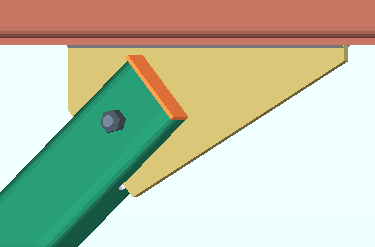
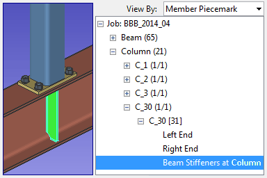
When a custom component is selected in the Model Tree , it is also selected in the model. This example shows a Beam Stiffeners at Column custom component. As the Model Tree shows, the stiffeners are a " Component " of the column. |
You can think of a custom component as being a set of controls for generating materials, cuts, holes, bolts and welds. In most cases those controls (the custom component) are associated with the same member that the materials, cuts, holes, bolts and welds are generated on. In the following table, note that the Safety Holes , Safety Tabs and Beam Stiffeners at Column custom components each perform operations on a member other than the member to which the component is added.
| Custom Component | Member Type |
| Base Plate Shear Key | Select a column with a base plate. The Base Plate Shear Key will become a component of that column. The shear key will be added under that column's base plate. |
| Beam Flange to Flange Connection ( |
Select one or more beams that have another (unselected) beam that crosses them. The custom component field bolts the selected beam(s) flanges to the crossing beam's flange. . |
| Beam Nailer Holes | Select a beam. The component is designed specifically for wide flange or channel beams, but may work with other beam main material types. |
| Beam Stiffeners - Beam ( |
Select the beam you want the stiffeners to be a custom component of. The stiffeners are added to that beam. |
| Beam Stiffeners at Column ( |
Select the column you want the stiffeners to be a component of. The stiffeners are added to the beam under the column. |
| Add CoreBrace Connection
|
Add a connection component to a CoreBrace member |
| E-Z Beam Release | Select one or more wide flange or welded plate wide flange beams. The custom component adds erection lift holes (slots) for the E-Z Beam Release tool, which is manufactured by Freedom Tools, LLC. |
| HSS Cap Plates ( |
Select any non-miscellaneous HSS member. |
| HSS VB Reinforcement Plates | Select a HSS rectangular or TS (tube) vertical brace. |
| Outrigger ( |
Select the wide flange beam you want the outriggers to be a custom component of. The outriggers are added to that beam. |
| Reduced Beam Section | Select the wide flange beam that you want to make "dog bone" flange reduction cuts to. |
| Safety Holes ( |
Select the beam you want the holes to be a custom component of. The holes are added to the supporting column based on the location of the beam. |
| Safety Holes - Column | Select the wide flange column that you want to add the holes to. The holes will become a component of that column. |
| Safety Tabs ( |
Select the beam you want the tabs to be a custom component of. The tabs are added to the supporting column based on the location of the beam. |
| Safety Tabs - Column ( |
Select the column you want the tabs to be a custom component of. The tabs are added to that column. |
| WWF Lifeline Holes | Select the welded plate wide flange beam that you want the lifeline holes to be added to and to be a component of. |
| CMU Opening , Concrete Wall Opening , Reveal , Surface Specific Cover , Thickened Slab | These components add openings or surface features to concrete or CMU members. |
| Additional Bars - Beam , Column Dowel , Dowel Path , Rebar Area Layout , Rebar Run , Rebar System , Repeated Rebar , Spiral Zone , Tie Zone , Tilt-Up Panel Reinforcement , Wall Dowel , Welded Wire Mesh Slab Reinforcement , | These components add reinforcement to concrete and CMU members. |
| Void Space Layout , Void Space Cylinder , Web Penetration with Stiffeners | Voids may be added to members of any type in order to designate cut outs and reduce their weight. The web penetration void with stiffeners may be applied to beams. |
| Base or Cap Plate Stiffeners , Column Stiffener at Beam , Column Stiffeners - Column | Components for applying stiffeners to columns.. |
Setup is available for setting the defaults on an edit window that opens when you add a certain custom component type. Not all custom component types have a setup window. When you choose Home > Project Settings > Job > Plugin Defaults > Component Plugin Defaults , those custom component types that have setup windows are listed on the selection dialog, and you can open the setup window for a particular component type by double-clicking its listing.
To add a custom component, Add Component > select the component you want. Once the custom component has been added to a member, it can be edited on the member edit window or on its own custom component edit window. The materials, etc. that are controlled by the custom component will be generated at the time that the component is added if User and Site Options > Modeling > " Automatically process after modeling operation " is set to ' Process and create solids '.
VIDEO 
The Beam Stiffeners at Column custom component adds beam stiffeners to a beam that is under the column that the custom component belongs to. To edit a custom component, you can do the same thing you would do to edit a connection component . With the selection filter set to ' Default ' or ' All ' or ' Custom Components ' (
), just double-click any material that was generated by that component. This will open the custom component edit window, not the member edit window. You can also edit a custom component by opening the edit window for the member that the custom component was added to. You will find settings for a custom component near the bottom of the member edit window. The materials, etc. that are controlled by the custom component will automatically be regenerated if User and Site Options > Modeling > " Automatically process after modeling operation " is set to ' Process and create solids '.
VIDEO Custom components can be selected and edited in the model when ' All ' or ' Default ' or ' Custom Components ' is the selection filter. This can also be done using the Model Tree . The Safety Holes component can only be selected in the Model Tree . To delete a custom component, select any material or etc. that was generated by the component, then press the Delete key (or choose Edit > Delete ). The component and its materials, etc. will be deleted immediately (without the need to Process and Create Solids ) if User and Site Options > Modeling > " Automatically process after modeling operation " is set to ' Process and create solids '. You can also delete a custom component on its member edit window (e.g., Beam Edit ), by doing a right-click on its listing in the navigation tree (left panel), then choosing " Delete " on the context menu.
VIDEO A beam is edited and " OK " is pressed so that the next beam added includes the components that were on the edited beam. On the newly added beam, the Beam Stiffeners - Beam component is deleted by selecting it then hitting the Delete key. The Safety Holes component is deleted on the Beam Edit window. On another beam, the Safety Holes component is deleted using the Model Tree . To move a custom component, choose Model > Component > Move . How a Move operation behaves depends on the component. Some custom components must be moved to a different member. Others can be moved on the same member. Still others cannot be moved at all. The component's materials, welds, etc. will be moved immediately (without the need to Process and Create Solids ) if User and Site Options > Modeling > " Automatically process after modeling operation " is set to ' Process and create solids '.
VIDEO A Beam Stiffeners - Beam custom component is moved and copied from one beam to other beams. To copy a custom component, choose Model > Component > Copy . Most, but not all, custom components can be copied from one member to another. The component's materials, welds, etc. will be copied immediately (without the need to Process and Create Solids ) if User and Site Options > Modeling > " Automatically process after modeling operation " is set to ' Process and create solids '.
VIDEO A Safety Holes custom component is copied from one beam to two other beams. Since the Safety Holes custom component does not generate material, the component needs to be selected in the Model Tree . Custom components can also be copied when you Member Copy or middle-click ( Repeat ) to add new members. User and Site Options > Site > " Member component items to copy/repeat " > " Custom components " sets whether or not components are copied when you middle-click ( Repeat ). " Copy custom components " on the window that opens for Copy Members controls whether or not components are copied for the Copy Members operation.
A custom component is set to "
Graphical " whenever you make graphical changes to any of its materials, bolts or welds. Graphical changes are changes such as adding a hole to a material, performing a cut or fit operation on a material, or editing or deleting a material, bolt or weld. In other words, graphical changes are those changes that are made to a custom component's materials, etc. outside of its edit window or its member's edit window. Tip: You can use Explode as described below to prevent this behavior.
VIDEO Setting a custom component to " To reduce a component to its constituent subparts, choose Model > Component > Explode . The component is erased, but its constituent parts (materials, welds, bolts) remain individually editable subparts of the original member they were generated on. Since the component will cease to exist, making changes to its parts will not cause it to be made "
VIDEO Exploding a custom component stops it from being a component and makes its constituent materials individually editable using the ' Default ' selection filter. The custom components that ship with SDS2 are Base Plate Shear Key , Beam Nailer Holes , Beam Stiffeners at Column (
Python coding: Like parametrics and custom members , custom components are coded using Python scripts. Consequently, users who are familiar with the Python programming language can develop custom components for use in SDS2. Code for custom components is maintained in the
plugins folder in the data directory for your current version of SDS2. Custom component plugins may also be placed in the
If you make changes to the member, but not the custom component, the custom component will still adapt to the changes you made to the member. For example, a full-depth stiffener added to a beam as a Beam Stiffeners - Beam custom component will adjust to the depth of the beam's " Section size " so long as "
Graphical " (
Custom components in the M odel Tree : To find a custom component in the Model Tree , set " View By " in the Model Tree to either ' Member Number ' or ' Member Piecemark '. The custom component will be listed under the member that it was Added to, after its connection components (labeled " Left End " and " Right End ") and before its submaterial and bolts.
Custom members
|
The handrail shown here is an example of a custom member. It looks and behaves much like regular member, but is actually generated using a Python script. |
Custom member basics:
- Custom members are members that are generated using Python -based plugins. These plugins are found in the
- Plugins for preinstalled custom members include: Hand Rail , Embed (angle and channel), Embed Plate , Anchor Rod , Caged Ladder , Roof Frame (
- Embeds defined in Concrete Setup > Embed Schedule are also custom members.
- Miscellaneous members are custom members. They provide superior functionality and ease-of-use characteristics to the legacy miscellaneous members that they can replace. Their plugins can be found in the
- Setup is available for setting the defaults on an edit window that opens when you add a certain custom member type. Not all custom component types have a setup window. When you choose Home > Project Settings > Job > Plugin Defaults > Member Plugin Defaults , those custom component types that do have setup windows are listed on the selection dialog, and you can open the setup window for a particular custom member type by double-clicking its listing.
- To add one of these members, press F2 then select the member type on the Member Type Selection window.
- The plugins from which SDS2-authored custom members are generated will have been originally installed in the
- The origin reference point for custom member is usually the 1st point that was located when the member was added, although there are exceptions.
- Custom members are not like beams, columns, braces and joists, which can generate connections with design calculations, and which allow you to adjust the loads that are applied to them. They are more like legacy miscellaneous members, except that they can be generated automatically.
- You can Copy and Move... (or Move... ) custom members. You can also Isolate custom members and add preset views. In the Model Tree , when ' Member Piecemark ' is selected for " View By ," custom members other than miscellaneous members are displayed under the ' Custom members ' category. Miscellaneous members are displayed under the ' Miscellaneous ' cagegory.
- You cannot multi-edit custom members.
- " Custom member section sizes " in Display Options lets you turn on/off the display of custom member section sizes in Modeling erection views. " Show section size on custom members " in Detail Erection Views lets you turn on/off the display of custom member section sizes when erection view drawings are auto detailed.
- Member status > Member type (
- To edit a custom member displayed in a solid form , you can double-click its main material . On a handrail, for example, the top rail is its main material and is also its reference line when it is displayed in stick form .
If you get a message like the following when trying to edit a custom member:

Cannot edit member xx of type yy because the plugin is not available.. 

The problem can be fixed by installing the appropriate plugin. Contact whoever sent you the Job and let them know that the plugin is missing. Once the plugin is installed, you will be able to edit the custom member. Also be aware of what it means for a custom member to be "
- Any changes that you make to custom-member materials outside of the custom-member edit window will cause the member to be made "
- For this reason, you should clean up a custom member using Model > Material tools only after you are certain that you will make no more changes on the custom member edit window.
- Although all preinstalled custom members have "
- If you make changes to a non-graphical custom member's materials outside of its edit window, you will get duplicate materials that overlap your outside-of-the-custom-member-edit-window material change whenever you later make a material change using the custom-member edit window.
Status Display: Member status > Member type (
Display Options: Custom member section size
The documentation button gives you access to the manual that you are currently reading -- SDS2 Help -- using a web browser when User and Site Options > General > " Modeling layout style " is set to ' Lightining '.
|
|
|
The documentation button opens SDS2 Help |
Also see: Help browser (chooses web browser that opens whenever you access SDS2 Help)
Embed assemblies Documentation in progress
Grid lines appear as lines, circles or arcs of a circle in Modeling . A grid line may have one of seven " Pen colors " and one of seven " Linetypes ," which means that the grid lines in your model may be somewhat different in appearance than those shown below. Also affecting the appearance of screen shots like those shown below is the option " Scale erection view bubbles " in Display Options .
|
|
|
|
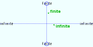
Straight grid lines are also erection views and are labeled with their names. They can be finite or infinite . To see the model from a straight grid line's view, just double-click its name or Open ( Ctrl + o ) and select the view by its name. |
|
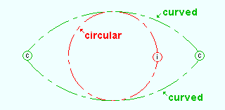
Curved grid lines are full circles or arcs of a circle. They are not elliptical, and they do not have views associated with them. Although you can't detail a curved grid line, the curved grid lines can be made to appear on erection view drawings. |
Both straight and curved grid lines:
- The default color for both straight and curved grid lines is the " Grid line/bubble pen color " that is specified in Home > Project Settings > Fabricator > Detailing > Drawing Presentation > the " Pens " tab. This setup option sets the default color for each new grid line that is added.
- Grid lines, both straight and curved , can be snapped to for point location using Locate options such as INCM and INCL .
- Both straight and curved grid lines can be turned on/off using Display Options based on their " Erection view type " designation of ' Primary ', ' Secondary ', etc.
- " Show grid bubbles on finite erection views " (
- Both straight and curved grid lines are selectable and editable when the ' Grid Lines ' selection filter is active. Double-clicking either of these types of grid lines when the selection filter is ' Grid Lines ' or ' All ' opens the Edit Erection View window.
- To multi-edit straight and/or curved grid lines, the selection filter must be set to ' Grid Lines ' or ' All '. First select the grid lines, then do a right-click and choose " Edit " on the menu .
- To delete straight and/or curved grid lines, the selection filter must be set to ' Grid Lines ' or ' All '. First select the grid lines, then press the Delete key.
- The Delete View tool applies to both straight and curved grid lines , as does selecting ' Erection views ' for the Delete Project Items or Rename Project Items or Copy Project Items utilities.
- An alternative to Delete View is to set the selection filter must be set to ' Grid Lines ' (
Straight grid lines:
- Straight grid lines can be infinite or finite . This is controlled with a check box that is named " Finite " (
- In the model, with ' Default ' the active selection filter , double-click the name of a straight grid line to open the view associated with that grid line. When the ' All ' selection filter is active, then double-clicking the grid line opens the Edit Erection View window, whereas double-clicking the name of the grid line opens the view.
- Tools for adding straight grid lines: Add Grid Line (
- Do not confuse straight grid lines with construction lines , which may look like and do behave like grid lines, but which are not labeled with their names and do not have erection views associated with them.
- Straight grid lines have erection views associated with them. You can open one of these views using Open View (or by double-clicking on the grid line's name). Erection views are permanent features of the Job unless you remove them using Delete View . You can even detail them using Detail Erection Views .
- Straight grid lines can be automatically dimensioned on erection view drawings based on the " Erection view type " (' Primary ', ' Secondary ', etc.) that has been assigned to them. Automatic dimensioning occurs when you Detail Erection Views .
- Straight grid lines can be relocated within the 3D model: Just perform an operation that changes the view's global coordinate position , then save the relocated view under its same name .
- An infinite grid line can be made finite by checking the box for " Finite " (
Curved grid lines:
- Tools for adding curved grid lines: Add Curved Grid, 3 Points (
- " Center of curved grid lines " (
) of a curved grid line . The center of the circle that a curved grid line is an arc of is an exact point in Modeling .
- A curved grid line cannot be auto detailed to create a erection view drawing. However, when you detail an erection view associated with a straight grid line, you can optionally show the curved grid lines on that view. To have the grid lines drawn, choose Detail Erection Views and choose to " Annotate erection views ." Also, the " Erection view type " of a curved grid line must be a choice other than ' Placement only ' for it to be drawn on the erection view drawing. On the erection view drawing, the curved grid line will be an arc .
Display Options: Show grid bubbles on finite erection views
Display Options: Scale erection view bubbles
Display Options: Center of curved grid lines
Holes, 3D are represented in Modeling by black-filled circles on the opposing surfaces of a material.

Important information about 3D holes: A set of hole tools (for 2D holes ) exists in the Drawing Editor . However, it is preferable to add/edit holes in Modeling since changes to holes in Modeling update the model, whereas changes to 2D holes in the Drawing Editor only alter a particular drawing. Also, holes added in Modeling can be CNC downloaded, whereas holes added in the Drawing Editor cannot be CNC downloaded.
Hole tools: Hole Mode , Add Holes , Match Holes , Edit Hole , Erase Holes , Set Reference Point . Add Holes opens the Hole Add window. Edit Hole and the various CNC tools open the Hole Edit window. To edit a hole, double-click the hole in Select Items mode when ' Default ' or ' Holes ' is the selection filter . The generic Delete tool can be used to erase holes, but it does not provide Change Options to remove the holes from like materials Setting a " Model completed " date on a member keeps hole tools from being able to change the holes on that member.
Display of holes: Holes are only displayed when the members they are associated with are displayed in one of the three solid forms . The display of " Holes " can be turned on/off in Display Options . When you zoom out in a view, hole display is turned off per User and Site Options > Modeling > " Level of detail ." Holes also disappear when depth checking causes your view to show the inside of a material's surface.
Hole setup options: " Add bolts when adding holes " for Add Hole . " Show balloon description " tells you the hole number and the member the material is a part of. " Show hole group reference point " applies when the mouse pointer (
Materials must be in a solid form for holes to be displayed. Holes are not displayed when you zoom out too far from a material. Also, holes are only displayed on the surface of a material, not when you are in the material.
Process and Create Solids automatically matches holes to member main material during its Create Solids phase.
A CNC mark is a hole with a diameter of zero.
Status Display: Hole status
Display Options: Holes
Layout nodes can be moved or deleted in Modeling .

|
Layout nodes appear as cubes displayed in the " Primary selection surface color " when you activate a tool such as Move Layout Nodes . |
Layouts are a feature of concrete slabs and concrete walls and welded wire mesh and various other members and components.
Members can be displayed in Modeling in stick form or any of three solid forms .
To select a solid form member with the filter set to ' Default '
|
||||
 |
|
|||
| 1 . Left-click ( Select ) the main material of the member you want. | 2 . The selected member turns the " Primary selection color " (green in this example). | |||
A member is more than just its main material . A member is also the submaterials, bolts and welds that shop attach to that main material. Together these items are transported from the fabricator to the construction site as a single shipping member. Except for the welds, the items that make up a member are listed in the member's bill of material .
As a reference for identification and tracking, members are assigned member piecemarks .
All member piecemarks are automatically tracked. Members that receive the same mark are depicted on a single member detail . For joists , which are not represented on member details, a joist report sorts joists by their member piecemarks.
Member types that incorporate connection design are beams , columns , vertical braces , horizontal braces and joists .
Other member types that may be found in the 3D model are miscellaneous members , legacy miscellaneous members , stairs and custom members .
To see a list of the members that are in your current view in Modeling , refer to the Model Tree . " View by " in the Model Tree can be set to ' Member piecemark ' or ' Member number '.
Status Display: Member status
Status Display: Group member status
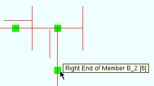
Member ends appear as cubes near the ends of members. In a plan view such as in the example below, you can see only one surface of the cube, and therefore each member end looks like a square.
|
These member ends are selected and are therefore the specified User and Site Options > Modeling > " Primary selection surface color ." When selected, ends become visible even when View > Display Options > " Member ends always displayed " is turned off. |
Display of member ends:
|
Member ends are useful for Move/Stretch and editing member pins:
- Double-clicking a member end opens the Member End Edit window, which lets review/edit the pins that have been applied to that end.
- The selection of member ends is important to Move/Stretch Members or Move/Stretch Members, Include Material . When only one end of a member is selected, the member is stretched, skewed or compacted. When both ends are selected (or the entire member is selected), the member is moved.
- To select a member end, left-click ( Select or Select + ) on it. Or you can draw an area box while in Select Items mode with the ' Default ' or ' All ' filters selected or with the filter for ' Member Ends ' selected.
- Except on very short members, these cubes are placed 1 foot from the exact point of each end of a member. This means that in order to select a member's end by area box, that cube needs to be within the depth checking limits.
- If the box is checked for User and Site Options > Modeling > " Show balloon description ," Modeling identifies the member end (left or right, member piecemark, member number) when you hover the end with your mouse pointer (
- The ' Member Ends ' selection filter lets you select member ends without selecting members.
Display Options: Member ends always displayed
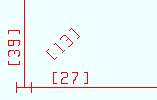
Member numbers [num in brackets] identify members -- including deleted members -- that exist in your current Job .
|
Member numbers are commonly identified in brackets [ ] on edit windows and erection views. Here they are shown on an erection view. |
Every member has a number:
Ways to find a member's number or to select a member by its number:
- View > Display Options > " Member numbers " can be turned on to display member numbers on members in Modeling .
- If View > Display Options > " Piecemarks " are set to be shown, then a member's member number is shown instead of its piecemark if that member has not yet undergone the Create Solids phases of Process and Create Solids .
- Process > Detail Erection Views > press the " Settings " button > the " Annotations " tab > " Show member numbers on erection views " turns on or off the display of member numbers on erection view drawings when those drawings are auto detailed.
- An easy way to find a member's number in the model is to turn on User and Site Options > Modeling > " Show balloon description ." The member's member number will then be shown on any member that you hover your mouse pointer (
- In erection views and on most selection dialogs and reports, a member's number is usually placed in brackets [num], though on some selection dialogs the number is not in brackets.
- In the Report Writer , the data source field for member number is Member.MemberNumber .
- The Advanced Selection attribute is MemberNumber . The Parametric module attribute is MemberNumber .
# Selects members with numbers greater than 45.
m.MemberNumber > 45
- You can employ the " Member number " condition using Status Select to select members by their numbers. Doing so is a good alternative to using Advanced Selection . You can also use that condition to color code or masks members using Status Display .
Status Display: Member status > Member number
Display Options: Member numbers
Member orientation indicators may appear in a plan view or elevation view in Modeling when a member is displayed in stick form . They illustrate the spatial orientation of a member's main material. The following examples show material orientation indicators on braces.
|
|||||||
| The stem of this W tee brace points away from you. | The leg of this angle brace points away from you. | The toes of this channel brace point away from you. | Legs of this back -to- back double angle brace point away. | ||||
Display of member orientation indicators:
Display Options: Member orientation indicators
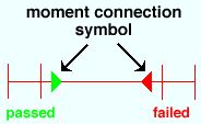
Moment connections are indicated by a triangle on the end of a supported beam. If the triangle is red , the " ![]() Moment " connection has failed. If the triangle is green , the connection has been successfully designed.
Moment " connection has failed. If the triangle is green , the connection has been successfully designed.
|
A yellow triangle (not shown) indicates a beam with a moment connection that has not yet undergone the Create Solids phases of Process & Create Solids . |
|
Display Options: Moment symbols
Notes are for authoring and reviewing comments related to the 3D model or to the project as a whole. To review a note, just double-click on it in Modeling , or use the Note Viewer . Notes are entirely user-configurable and fully contained in your current Job , which means that if you transfer that Job to another network, the notes in that Job will be transferred with the Job.
|
|
|
|
|
To read a note, double-click it, or read it in the Note Viewer . The Note Viewer can even review notes that are not shown in the model. |
|
Hovering a note may show a tool tip ( balloon description ) with the note's " Subject " and other information. |
- Notes are a part of your current Job. This makes them a great tool for communicating information between workstations and across disciplines.
- One or more " Attachments " such as text files, or PDF files, or spread sheets, or graphics files can be added to the comments in a note to provide details about the modeling situation that the note addresses.
- Tools for notes can be found on the Model menu in Modeling . These include: Add Note to Model , Note Viewer , Copy Notes , Move Notes . To delete a note , select it in the model or in the Note Viewer , then hit the Delete key.
- To display notes in the model, you need to check the box for " Notes " in Display Options . Be aware that some notes -- ' Project ' notes -- cannot be displayed in the model. You need to use the Note Viewer to view such notes.
- Tags can be applied to notes to serve as filters (sorting keys) in the Note Viewer so that you can more easily find a particular set of notes within a large database of notes. The tags that are supplied, by default, at Home > Project Settings > Job > Predefined Note Tags are appropriate for use in the steel fabrication industry, but can be added to or changed. For example, you could change the tags to the letters of the alphabet, then file the notes under "A" "B" "C" or etc.
- Before you can add an " Attachment " to a note, you need to first add a " Comment " to the note. The comment might provide information about the attachment, or a comment can be added without an attachment. Since multiple comments can be added to a note, multiple attachments can be added to the note.
- The Note Viewer can show all notes in the database of notes that is maintained in your current Job . Or you can choose to show, in the Note Viewer , only those notes which are of a particular " Type " and/or have a particular " Discipline " and/or " Status " and/or " Custom " tag. You can double-click any note that is shown in the Note Viewer to open that note's Edit Note xxx window. On the Edit Note xxx window, you can change the note, if you so choose.
- Notes should not be confused with Edit Properties "
 Notes ," which are a different animal.
Display Options: Notes
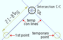
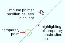
Noticed points & temporary construction lines may be generated during the location of a first or second point. The noticed points and temporary construction lines disappear when the point has been located. The first point that you locate in an operation will persist, as a noticed point, into the second-point location phase of the operation.
|
To create a noticed point, with "
) over the location where you want that point and hover the center of the target with your mouse pointer (
Temporary construction lines may be generated -- at 45° screen coordinate increments -- through any noticed point, including the first point that is located in an operation. These temporary construction lines become visible -- one at a time for most point locators, one or two at a time for INCL -- whenever you are able to locate a point on them. You can locate a point on a temporary construction line using INCL or ONLN or INCM or INCR . Also, you can base off construction lines using BSCL . The temporary construction lines always exist, behind the scenes, at 45° intervals through noticed points, but they only become visible when you can locate a point on them. Optional: Point Location Configuration has an option ( click here ) to turn off the addition of construction lines at 45° increments.
To get a temporary construction line at any angle, locate a point, type @ , then type the angle (a number of degrees). A temporary construction line will be generated through that first point at that angle during second point location using a locator such as ONLN or etc. Another way to get construction lines at any angle is to set the UCS as described below.
UCS considerations: If the UCS (User Coordinate System) is toggled on, and the UCS plane is parallel with the screen axes, the temporary construction lines will align, at 45° increments, with the UCS . When the UCS is toggled off, the temporary construction lines align at 45° screen coordinate increments. To rotate the UCS , use Rotate UCS .
|
For INCL point location, one or two temporary construction lines become visible whenever an INCL point is locatable using them. This example shows two temporary construction lines. |
|
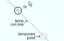
For ONLN point location, a temp construction line may be shown at 45° increments through a noticed point. Note, from this example, that the target ( |
|
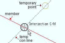
For INCM point location, a temporary construction line may be shown at 45° screen coordinate increments through the noticed point that is closest to the member workline . |
|
For BSCL , just hover your mouse pointer ( |
Key concept: As you can see in all of the above examples, a temporary construction line may be shown at 45° screen coordinate increments through a noticed point.
A temporary construction line disappears temporarily when you move your mouse pointer (
Temporary construction lines disappear permanently when the noticed points which generate them disappear. Noticed points disappear, taking their construction lines with them, when you left-click ( Locate ) a point, or when you end an operation, for example, by doing a right-click ( Return ).
YouTube: Point Location / User Coordiante Syatem, v7.3 (
Origin reference point ( for members/materials ) identifies the 0, 0, 0 material / member coordinate of a material / member when -- in Modeling -- you Rotate Material or Edit Member or when you hover a material with the ' Material ' selection filter selected or when you hover a member with the ' Member ' or ' Default ' selection filter selected.
![]()
A member's origin reference point:
A material's origin reference point:
Piecemarks may be displayed on a member's left end in an erection view. This only applies to member piecemarks , not material marks.
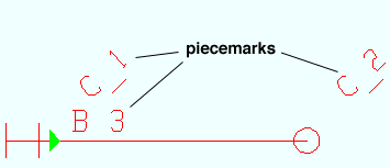
Piecemarks in Modeling:
- View > Display Options > " Member piecemarks " can used in Modeling to turn on/off the display of piecemarks.
- If a member has not yet been assigned a piecemark, the member's member number rather than its piecemark is shown on its left end.
- You can also tell a member's piecemark (along with its member number) by looking at the status line while using Show Sequence .
- A balloon description (optional) tells you a member's piecemark and member number when you hover over that member with your mouse pointer ( ) in Select Items mode.
- Piecemarks can optionally be included or excluded when erection views are Detailed .
- On erection view drawings, piecemarks look like labels, but they are not labels (since you cannot use Label tools to change them). They can be changed on erection view drawings using Evu Cleanup tools.
Piecemarks on erection views in the Drawing Editor:
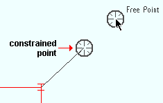
The point location target ( ![]() ) snaps to various on-screen positions as you move your mouse pointer (
) snaps to various on-screen positions as you move your mouse pointer ( ![]() ) while various Locate options are active. The target centers over the location where a point will be located when you left-click ( Locate ). The point location target is used for operations such as Construction Line Add , Add Beam and Add Grid Line .
) while various Locate options are active. The target centers over the location where a point will be located when you left-click ( Locate ). The point location target is used for operations such as Construction Line Add , Add Beam and Add Grid Line .
|
|
An example showing two targets . ANNO is turned off in this example, and therefore no dimensions are shown. The example was created by typing a distance . A similar example could be created using the Offset Controls . |
|
|
|
the ' Fancy ' target |
Tip 1: Look at the X-Y-Z display to determine X, Y, Z global coordinates (in Modeling ) of the snap point where the point location target is at. In the Drawing Editor , the X-Y-Z display shows the drawing coordinates.
Tip 2: When the UCS is on (" Toggle UCS " is gray ), the X-Y-Z display will show X, Y, Z values that indicate the point location target's distance from the UCS origin point. This lets you take measurements from that point by simply referring to the X-Y-Z display -- without having to use the Ruler .
Reference drawings in Modeling
|
This example shows a 2D erection view that was added as a reference drawing to a plan view in Modeling . The grid bubbles and dimension lines (white) along with the callout text (yellow) are elements of the reference drawing. The red member lines are actual members in the model. |
Drawing Editor drawings can be placed in Modeling :
Tools for reference drawings in Modeling :
- Reference Drawing Tools gives you the complete tool set for adding or manipulating a reference drawing.
- The insertion point for a reference drawing can be changed in the Drawing Editor using Verify Reference Point , or it can be changed on the Reference Drawing Tools window (in Modeling ) using the " Set Reference Point " button.
- A " Show " check box is available, on the Reference Drawing Tools window, for each reference drawing that has been placed in the model and can be used to turn on (
- The appearance of a reference drawing in Modeling should match the appearance of its Drawing Editor equivalent, with arcs , lines , circles , clouds , dimensions , images , members of various " styles ," labels of various fonts and all other object types properly rendered.
- Point locators such as INRL , MDPT , INCR , INCL , EXPT , INRM or Auto Point can be used in Modeling , along with the Locate option REFD , to locate points on a reference drawing.
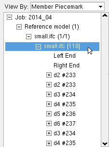
A reference model member is a member type. When a reference model is imported into Modeling , the entire model is attached to a single reference model member that has its piecemark named after the file that the model was imported from. The member is also assigned a " Sequence ." Attached to the reference model member are one or more dummy materials . An IFC reference model member may also have bolts attached to it. A reference model member does not have a stick member line. Model > Member > Move/Stretch or Model > Member > Move/Stretch Include Material can be performed on a reference model member to relocate the reference model's position in Modeling .
|
A reference model member is shown here, selected in the Model Tree . In this example, multiple dummy materials are attached to the reference model member. Selecting in the Model Tree with the selection filter set to ' All ' or ' Reference Models ' also selects the reference model in the model. Deleting a reference model member is generally not a good idea. If you do accidentally delete the member, you can Undelete to get it back. The better way to remove a reference model is to use " Unlink " ( |
A. One identifying characteristics of a reference model is that it is associated with a reference model member . Another identifying characteristic is that it will be listed on the Reference Models window (
Q. How do you import a reference model?
A. Use Import Model to import a DGN or DWG or IGES or STEP file. Or, in Modeling , use Model > Reference Model to import a DGN, DWF, DWG, IGES, STEP or IFC file.
Q. Can I use " Refresh " and " Unlink " on a reference model imported using Import Model ?
A. Yes. It does not matter whether the reference mode was imported via Import Model or by using the " Link to New File " button that can be found Reference Models window in Modeling .
Q. Is a reference model an actual, imported model?
A. Yes. When you import a reference model into Modeling , the information in that model becomes associated with a reference model member that is assigned a member piecemark which is named after the importing DGN, DWF, DWG, IGES, STEP or IFC file. The dummy materials that attach to the reference model member are assigned submaterial marks (d1, d2, etc.).
Q. Why does not " Link to New File " just link to the DGN, DWF, DWG, IGES, STEP or IFC instead of actually importing the model?
A. By truly importing the model instead of just linking to it, the reference model is made more interactive. This means, for example, that you can actually measure the clearance between the reference model and the SDS2 model using the Ruler and various Locate options. You can also use the reference model for reference points when you Add Material or Add Assembly or Material Copy . The dummy materials that are imported can be used to generate Material Construction Lines . You can even move a reference model member using Move/Stretch Members or Move/Stretch Members, Include Material . The down side of importing the reference model in this way is that storing the new member and material information increases the size of the Job.
Q. Are there differences between models imported using " Link to New File " as opposed to Import Model ?
A. Not for DGN, DWG, IGES and STEP files. In some pre-v2018 versions of this software, there were some differences, but now either method imports exactly equivalent reference models.
IFC files, on the other hand, behave in substantially different ways when imported using " Link to New File " as opposed to using Import Model. When imported using " Link to New File ," an IFC model is a reference model. When imported using Import Model , an IFC model is an interactive model.
IFC imported using " Link to New File " Multiple dummy materials may be attached to the reference model member . If bolts are imported, they are imported as bolts. IFC imported via Import Model members are imported as beams, columns, etc. These can be edited in the SDS2 model. The model is not a reference model and will not appear on the Reference Models window. Q. I have several reference models. How can I isolate one particular model from the other models?
A. While in a Modeling view in which the model can be made visible, choose Model > Reference Model to open the Reference Models window, then check the box for "
Q. What happens if I delete or move the file used to create the reference model?
A. Removing or deleting the DGN, DWF, DWG, IGES, STEP or IFC file that was used to create a reference model does not remove the reference model itself. The reference model will persist in Modeling , and all options on the Reference Models window -- with the exception of " Refresh " -- will be operational. On the Reference Models window, red highlighting of the removed file's " Filename " will indicate that the file itself has been deleted (or moved from its original location). To actually remove the reference model itself, you can press the " Unlink " button.
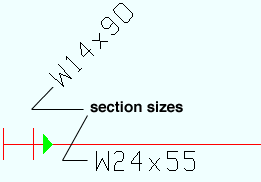
|
In Modeling erection views, section sizes are displayed (or not displayed) per View > Display Options > " Member section sizes ." |
Section sizes can be displayed in Modeling or Drawing Editor erection views:
- The actual printed " Character height " of section sizes can be changed in Home > Project Settings > Fabricator > Detailing > Drawing Presentation > the " Sizes " tab.
- Section sizes can optionally be included or excluded when erection views are Detailed .
- On erection view drawings, section sizes look like labels, but they are not labels (since you cannot use Label tools to change them); they can be changed on erection view drawings using Evu Cleanup tools.
- Members with steel grades that have a " Nonstandard Notation " on their steel grade window at Home > Project Settings > Job may optionally have that nonstandard notation written next to their section size. In a Modeling erection view, the notation appears when " Section sizes " are shown and the " Denote non-standard material " setup option is turned on. To get the annotation on an erection view drawing, you need to check the box for " Denote non-standard material " when you auto detail the erection view.
- A miscellaneous member will display the " Description " of its " Main member material " when "
Shear plate side indicators may be displayed in Modeling on the ends of beams with single-plate shear connections if the box is checked for " Shear tabs " in Display Options ( View > Display Options ). and when those members are displayed in stick form .
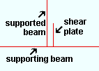
|
The shear plate in this example is on the near side of the left end of the supported beam. |
Also see: Show shear tab location on erection views ( Detail Erection Views window) sets whether the shear plate side indicator is shown on erection plans.
Display Options: Shear tabs
Erection View Cleanup: Left end shear tab symbol
Terrain can be made to appear in Modeling erection views.
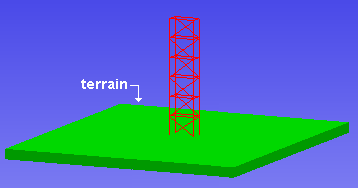
Tip: In your day-to-day work as a detailer, you probably don't want to show terrain. However, when you take screen shots or video captures of your model, you may find that showing the terrain is a good way to showpiece your work.
Display Options: Terrain (to turn the display of terrain on or off)
Setup: User and Site Options > Modeling > " Modeling background color 1 " and " Modeling background color 2 ."
Setup: Top of terrain (global coordinate positioning of the terrain)
Setup: Thickness of terrain
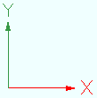
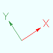
UCS axes ( Modeling and Drawing Editor )
|
A user coordinate system (UCS) is tied to the 3D model in much the same way that the global coordinate system is tied to the 3D model. |
|
The UCS axes rotate to indicate the orientation of a view that you Open . To reorient the axes within a view, you can use a UCS icon such as the " Rotate UCS " icon. |
Turning UCS axes on can be done in a Modeling erection view or a Drawing Editor drawing when you click the " Toggle UCS " icon so that it is gray (
). Click that same " Toggle UCS " icon again, so that it is white (
), and you will turn the UCS axes off.
When UCS axes are on (shown), ORTHO snaps to the UCS axis that is closest to your mouse pointer (
When UCS axes are off (not visible), ORTHO snaps to the X or Y screen axis , whichever is closer.
General information about the user coordinate system:
YouTube: Point Location / User Coordinate System, v7.3 (
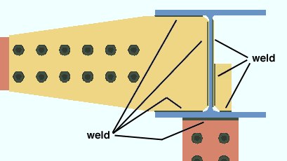
3D shop and field welds
|
3D welds can be made to appear in Modeling when members are displayed in any of the three solid forms . |
Shop and field welds: Welds can be shop welds ("
3D welds can be drawn on erection view drawings: For auto detaling of erection view drawings, there are two options -- " Show 3D field welds " and " Show 3D shop welds " -- that turn on/off the depicting of shop and/or field welds on a erection view drawing.
How welds get into the model: The 3D welds illustrated above were generated automatically during the Create Solids phases of Process and Create Solids . Welds can also be added by users in Modeling using Add Weld . 3D shop welds show up as weld symbols on member details in the Drawing Editor . Field welds, like field bolts, do not appear on member details.
Weld symbols: An alternative to adding 3D welds in Modeling is to add weld symbols to member details in the Drawing Editor using Weld Add . Adding weld symbols in this way does not change the 3D model, but it does provide welding instructions to the shop.
Maintaining user changes to welds: Setting a " Model completed " date on a member prevents welds from being altered on that member.
Copying and Saving: You can save welds and bolts along with materials when you Model > Assembly > Save or when you edit or create a new assembly in the Assembly Editor . Model > Assembly > Add places a copy of the weld that you have saved. Bolts can be copied using Model > Material > Copy .
Status Display: Weld status
Display Options: Welds
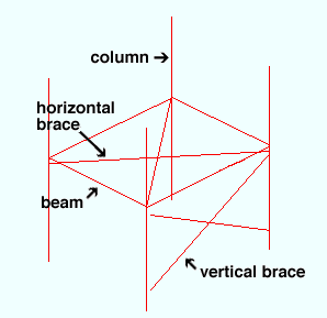
Work lines (member lines)
|
Member lines represent the work lines of members when those members are displayed in stick form . Each end of a member work line is an exact point ( EXPT ) that corresponds to the work point defined when the member was Added . Mid Point ( MDPT ) can be used to locate the midpoint of a member's work line. In Modeling , INRM -- together with REFD -- can find intersections of lines on a reference drawing with member lines in the model. In the Drawing Editor , INRM can be used to find intersections of member lines with lines or circles or arcs. INCM can find intersection of construction lines with members. |
Beam member lines are drawn across the top flange center line of a wide flange or S shape or welded plate wide flange beam. For a channel beam, the work line is at the heel of the top flange of the channel. Most beams are input with their work points at the work lines of other beams or the work lines of columns.
Girt (legacy) and Purlin work lines are oriented the same as beam work lines, with the work line running along the top flange of the member.
Column member lines are drawn through the neutral axis of a wide flange , S shape or welded plate wide flange , HSS round (pipe) or HSS rectangular (tube) column. Columns can frame to beams or be spliced to other columns, but often frame to nothing.
Horizontal brace member lines for W tee or S tee or wide flange or S shape horizontal braces are drawn across the top flange center line. For an angle horizontal brace, the work line is drawn along the leg to gusset per Horizontal Brace Edit > "
Vertical brace member lines are drawn through the neutral axes of wide flange , S shape or welded plate wide flange , HSS round or HSS rectangular braces. For a W tee or S tee vertical brace, the work line is drawn through the top flange center line if the stem is ' Horizontal ' or along the connection bolt line nearest the tee flange if the stem is ' Vertical '. For a single angle vertical brace, the work line is set per Vertical Brace Edit > "
Joist member lines are displayed in Modeling per the choice made to View > Display Options > " Joist outline ."
Stair member lines are displayed in Modeling as a single member line or an outline as a single member line per the choice made to View > Display Options > " Stair outline ."
Display Options: Member lines
Work plane highlighting
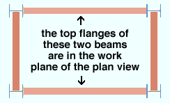
|
The top flanges that are lighter in color are at the elevation of the plan view . The darker beams are at a lower elevation. |
Why is work plane highlighting important?
- Work plane highlighting helps you identify the work plane of a view. Surfaces that are in the work plane of a view are displayed in a lighter color.
The work points of objects added in Modeling may snap to a view's work plane:
- The work plane of a view is the plane that, for example, holes are placed on when you Add Holes .
- For Add Member and Construction Line Add and Add Material operations, INCL points snap to the work plane of the view.
- When you use FRPT as a point locator, the point location target (
- Tools that move the work plane of a view include Snap to Surface , Snap to Farside Surface , Snap to Adjacent Surface , Reference Elevation , Relative Depth , Section View .
- The work plane of a plan view is its Reference Elevation .
Changing the work plane:

