Nonstandard Field Bolts on Erection Views
- General Overview
- Tips and Tricks
- Related Tools
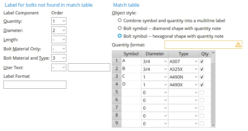
Label for bolts not found in match table
Quantity: The quantity of non-standard field bolts at the connection in an erection view drawing.
Diameter: The diameter of non-standard field bolts at the connection in an erection view drawing.
Length: The length of non-standard field bolts at the connection in an erection view drawing.
Bolt material only: The bolt material of non-standard field bolts at the connection in an erection view drawing. (e.g., A325, A490, F1852N, etc.)
Bolt material and type: Any bolt type that is listed at Home > Project Settings > Job > Bolts, Washers, and Holes > Bolt Specifications can potentially be called out on an erection view detail when a numerical Order has been assigned here. (e.g., A325N, A490SC, F1852N, etc.)
User text: Any combination of up to 16 numbers (1, 2, 3, etc.) and/or letters (a, b, c, etc.) and/or special characters (*, ø, etc.). Special characters can include any of the Latin 1 characters 0160 to 0255. Characters that can be entered in the Drawing Editor as Label text should also be able to be entered here.
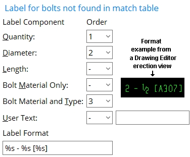
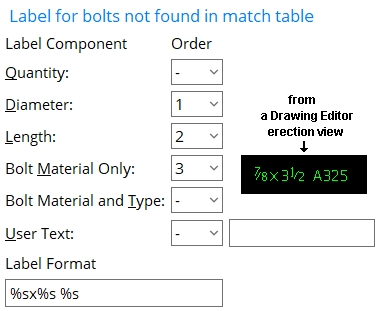
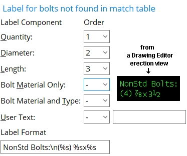
Label format: Sequential information consisting of %s and other characters. Each %s stands for an item that has been assigned a numerical Order. This means, for example, if four items have been assigned a numerical order, four %s should be included in the Label format. The first %s in the Label format stands for the item that has been assigned an Order of 1. The second %s in the Label format stands for the item that has been assigned an Order of 2. Blank spaces are recognized as distinct characters. A line break can be created using \n.
|
The first %s in this example stands for Quantity. The second %s stands for Diameter. The third %s stands for Bolt material and type. Space - [ ] are other characters that are used in this example |
|
The first %s in this example stands for Diameter. The second %s stands for Length. The third %s stands for Bolt material only. X and space are other characters that are used in this example. |
|
In this example, \n (new line) is used to create a line break. Note that the characters "NonStd Bolts" are typed to Label format instead of being entered as user text. |
Match table
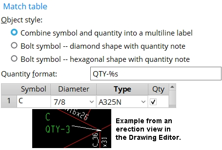
Object style: ![]() Combine symbol and quantity into a multi-line label or
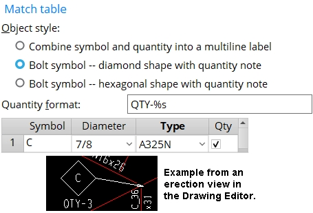
Combine symbol and quantity into a multi-line label or ![]() Bolt symbol -- diamond shape with quantity note or
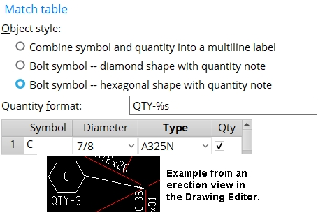
Bolt symbol -- diamond shape with quantity note or ![]() Bolt symbol -- hexagonal shape with quantity note
Bolt symbol -- hexagonal shape with quantity note
|
|
|
Quantity format: This applies to lines in the Match table that have Qty turned on (checked). The %s in the format instructs Erection View Detailing to report the quantity of non-standard field bolts at the connection that is called out in the drawing. Other characters can be included before and after %s.
Also see: The Quantify format that is entered here populates the Note text on a bolt symbol. For a multi-line label, this format populates the second line of the label's Label text.
Symbol: any combination of up to 16 numbers and/or letters and/or special characters. See the examples.
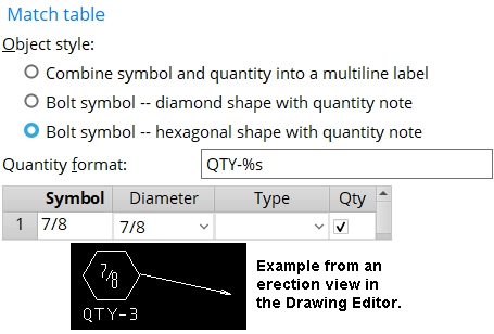
|
numbers are specified in this example. The resulting symbol calls out all groups of 7/8 inch bolts, regardless of their type, so long as the standard Bolt diameter for the project is not 7/8. |
Also see: The Symbol that is entered here populates the Symbol text on a bolt symbol. For a multi-line label, this text populates the first line of the label's Label text.
Diameter: 0 (any diameter) or a specific bolt diameter. You can either type in the diameter of bolt, or select a bolt diameter from the combo box ![]() )
)
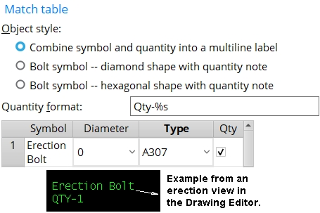
|
0 signifies a bolt of any diameter. When this example is applied to an erection view in a project where the standard Bolt type is something other than an A307, every group of A307 bolts in the erection view is labeled as Erection Bolt regardless of the diameter of bolts in that group. |
Type: blank or A325 or A325N or A325SC or A325X or any other bolt listed in the Bolt Specifications. You cannot type an entry to this field. You need to select the bolt you want from the list box ![]() )
)
|
|
Leaving Type blank results in the bolt type of non-standard bolts being ignored. If you leave the Type blank, you must enter a Bolt diameter.This example finds all groups of 7/8 inch bolts, regardless of their type, so long as the standard Bolt diameter for the project is not 7/8. |

|
An entry such as A325 -- where A325 is the bolt material only -- finds all bolt types made from that bolt material. In this example, A325 will find A325N and A325SC and A325X bolts that are non standard. |
Qty: ![]() or
or ![]() . This applies when a Symbol and Diameter and/or Type have been entered to a particular line on the Match table.
. This applies when a Symbol and Diameter and/or Type have been entered to a particular line on the Match table.
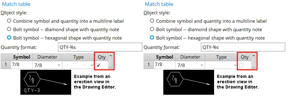
If this box is checked (
), Erection View Detailing calls out the quantity of non standard bolts in bolt groups that match the Diameter and/or Type specified on this line of the Match table. The quantity will be called out based on the Quantity format, which populates the Note text on a bolt symbol. For a multi-line label, the quantity format populates the second line of the label's Label text.
If the box is not checked (
), Erection View Detailing does not call out the quantity for bolt groups specified on this line.


|
|
OK (or the Enter key) closes this screen and applies the settings.
Cancel (or the Esc key) closes this screen without saving any changes.
Reset undoes all changes made to this screen since you first opened it. The screen remains open.
- Non-standard bolts are bolts that are not the standard bolt. Bolt Settings sets the standard bolt to be a bolt that is both the standard Bolt diameter and the standard Bolt type.
- Callouts for non-standard field bolts consist of a pointer and either a label or a bolt symbol. The auto detailing program finds on the erection views the field bolts of members that are field bolted even if the field bolts themselves are not shown.
- Settings applied to the Nonstandard Field Bolts on Erection Views screen are for your current Fabricator. A different set of settings will apply when you Change Fabricator.
- Red or yellow exclamation point icons
 or
or 
- Non-standard field bolts (Detail Erection Views > press Settings)
- Field bolts (the Class of bolt that this window pertains to)
- Bolt diameter (Bolt Settings, sets diameter of the standard bolt)
- Bolt type (Bolt Settings, sets the type of the standard bolt)
- \n (new line) (can be used to create a line break)

