Bolt Symbol Edit Window
- General Overview
- Related Tools
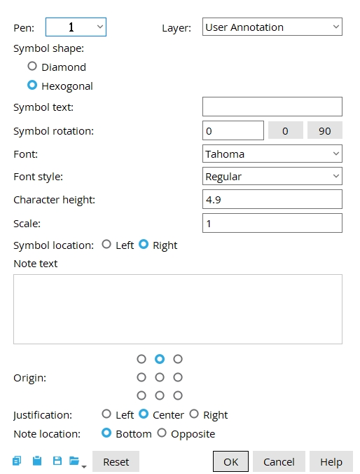
Pen: 1-7. Select the printing pen number (and on-screen display color) of the bolt symbol.
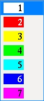
Tip:Line Weights sets the printed thickness for each of the seven pen numbers.
Layer: The drawing layer the bolt symbol is drawn on.
Defaults: For an add operation, the default selection made here is the layer that was selected on the
Layer Panel before you began the operation. For an edit operation, the default selection is the layer that the bolt symbol is currently on.
Symbol shape: ![]() Diamond or
Diamond or ![]() Hexagonal
Hexagonal
|
|
Diamond creates a diamond-shaped bolt symbol.
Symbol text: Any combination of up to 16 numbers and/or letters.
|
Symbol rotation: The number of degrees from 180 to -180 that sets the rotation of the bolt symbol with respect to its exact point . The location of that exact point is shown with a cyan dot ( o ) when a bolt symbol is selected.
|
|
0 degrees orients the symbol horizontally.
A positive number of degrees specifies the amount of counterclockwise rotation from horizontal.
A negative number of degrees specifies the amount of clockwise rotation from horizontal.
Font: Any font that is listed can be selected for the Symbol text and Note text of the bolt symbol.
|
For a TrueType font , such as any of those shown here, set the Width/height ratio to 0.6 to have the font rendered at its native width. |
Font style: The style ( Bold or Bold Italic or Italic or Regular ) of the selected Font. Different fonts may have different styles available to them.
Character height: The height ( in millimeters ) of letters/numbers that make up the characters of the Symbol text and Note text .
|
Font dependencies: This applies to whatever font is selected as the bolt symbol Font , regardless of whether that font is a TrueType font or the SDS2 font.
|
|
|
A number less than 1 reduces the size of the bolt symbol by a factor equal to the number entered.
1 is the default size of the bolt symbol. The font size on such a symbol is controlled by the Character height that is set on this window.
A number greater than 1 increases the size of the bolt symbol by that factor.
Symbol location: ![]() Left or
Left or ![]() Right. The choice made here positions the symbol to the left, right, top or bottom of its exact point . That exact point is shown as a cyan dot ( o ) when a symbol is selected.
Right. The choice made here positions the symbol to the left, right, top or bottom of its exact point . That exact point is shown as a cyan dot ( o ) when a symbol is selected.
|
|


Note text: Blank or a string of characters.
|
Note text is optional. To remove a note, simply delete the Note text characters, leaving the field blank. |
Multi-line text: When your cursor is in the Note text entry area, the Enter key creates a line break, resulting in multi-line note text.
Origin: Lower left or Left center or Upper left or Lower center or Center or Upper center or Lower right or Right center or Upper right . This applies to Note text.
|
This example shows labels, not Note text. When a label is selected you can see the origin ( o ) that the label is positioned with respect to. Note text works the same way,. but you have to infer the position of the origin -- you can't see it. |
Justification: This applies to multi-line Note text.
|
|
|
Note location: ![]() Bottom or
Bottom or ![]() Opposite. This applies to Note text. The choices shown here are not relevant under certain circumstances.
Opposite. This applies to Note text. The choices shown here are not relevant under certain circumstances.
This bolt symbol's note text ( QTY-3 ) is positioned so that its Note location is Bottom.
This bolt symbol's note text ( QTY-3 ) is positioned so that its Note location is Opposite and its Origin is Left center.


|
|
OK (or the Enter key) closes this screen and applies the settings.
Cancel (or the Esc key) closes this screen without saving any changes.
Reset undoes all changes made to this screen since you first opened it. The screen remains open.

