Detail Erection View Defaults window ( Detail Erection Views > press " Settings ")

The Detail Erection View Defaults window :

This window opens when you select erection view(s) for auto detailing then press " Settings ." It controls the auto detailing of those erection views. The settings that you specify on this window are saved with those selected erection views when you press " OK ." Tip: Press the " Default " button to overwrite these settings with choices made in Home > Project Settings > Fabricator > Detail Erection Views Defaults .

Also see :

page 1 | contents | process > detail erection views > press "settings" | top


Appearance Annotations Piecemarks

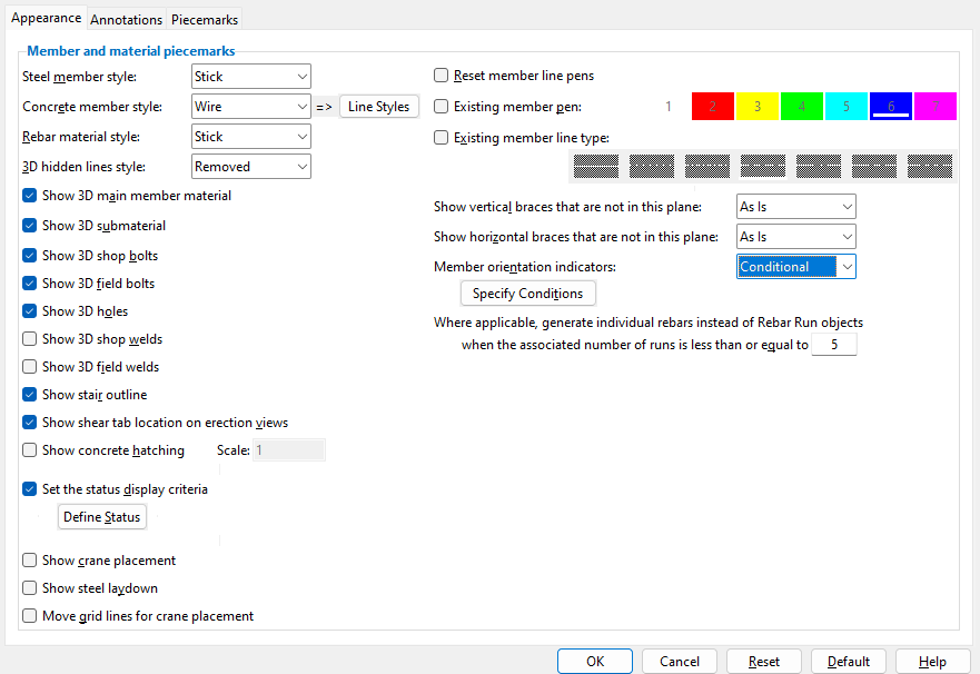
------ Member and material appearance ------

Steel member style: Stick or Wire or Solid or Stick + wire or Stick + solid . These options set how steel is drawn in the particular erection view(s) you are detailing. Piecemarks and section sizes can be shown for any of these options.

' Stick ' causes members in the to-be-detailed erection view(s) to be represented with a single line along the workline of each member. ' Stick ' members use the " Member orientation indicator s " setting that is applied on this window.

' Wire ' causes materials that make up members in the to-be-detailed erection view(s) to be drawn with lines showing their true structural shape.

' Solid ' causes materials that make up members in the to-be-detailed erection view(s) to be drawn to proportion and shaded according to their " Surface finish ."

' Stick + wire ' combines stick form and wire form representations. ' Stick + wire ' members use the " Member orientation indicator s " setting that is applied on this window.

' Stick + solid ' combines stick form and solid form representations.

Defaults: Home > Project Settings > Fabricator > Detail Erection View Defaults sets the choice (' Stick ' or ' Wire ' or ...) that is made here by default when you auto detail an erection view for the first time. Changes made on this window are saved with the erection view drawing(s) you selected before pressing " Settings " to open this window but do not affect the window in Fabricator Setup . To repopulate this window with the defaults from Fabricator Setup , you can press the " Default " button.

Also see:

VIDEO

The way it used to be : Two erection views are detailed with " Member style " set to ' Manually '. In v2020 and newer, the ' Manual ' detailing method has replaced selecting ' Manually '. (Recorded in SDS2 Detailing , v7.3.)

Concrete member style: Hidden or Stick or Wire or Solid or Stick + wire or Stick + solid .

' Hidden ' hides concrete members in the to-be-detailed erection view(s). They are not represented as hidden lines; instead, they are not shown. However, the member's rebar may be shown if the choice made to " Rebar member style " is not also ' Hidden '.

' Stick ' causes concrete members in the to-be-detailed erection view(s) to be represented as single lines or as simple linear layouts, depending on the concrete member type.

' Wire ' causes concrete materials in the to-be-detailed erection view(s) to be drawn with lines showing their true structural shape.

' Solid ' causes concrete materials in the to-be-detailed erection view(s) to be drawn to proportion and shaded.

' Stick + wire ' combines stick form and wire form representations.

' Stick + solid ' combines stick form and solid form representations.

Defaults: Home > Project Settings > Fabricator > Detail Erection View Defaults sets the choice (' Stick ' or ' Wire ' or ...) that is made here by default when you auto detail an erection view for the first time. Changes made on this window are saved with the erection view drawing(s) you selected before pressing " Settings " to open this window but do not affect the window in Fabricator Setup . To repopulate this window with the defaults from Fabricator Setup , you can press the " Default " button.

Line styles (for concrete members): This applies when the " Concrete member style " is ' Wire ' or ' Stick + wire '. When a concrete member type is checked ( ) in the Concrete Member Line Styles table, members of that type will be detailed with the line style selected.

opens a table like the one shown below

Defaults: Home > Project Settings > Fabricator > Detail Erection View Defaults sets the choice of line style that is made here by default when you auto detail an erection view for the first time. Changes made on this window are saved with the erection view drawing(s) you selected before pressing " Settings " to open this window but do not affect the window in Fabricator Setup .

Rebar member style: Hidden or Stick or Wire or Solid or Stick + wire or Stick + solid . This applies when ' Stick ' is not the " Concrete member style ." These options set how rebar is drawn in the particular erection view(s) you are detailing.

In these examples, ' Wire ' is the " Concrete member style ."

' Hidden ' hides the reinforcing bars in the to-be-detailed erection view(s). They are not represented as hidden lines; instead, they are not shown. However, a rebar run symbol may be generated where applicable.

' Stick ' causes reinforcing bars in the to-be-detailed erection view(s) to be represented with a single line along the workline of each bar.

' Wire ' causes rebar shape materials in the to-be-detailed erection view(s) to be drawn with lines showing their true structural shape.

' Solid ' causes rebar shape materials in the to-be-detailed erection view(s) to be drawn to proportion and shaded.

' Stick + wire ' combines stick form and wire form representations.

' Stick + solid ' combines stick form and solid form representations.

Defaults: Home > Project Settings > Fabricator > Detail Erection View Defaults sets the choice (' Stick ' or ' Wire ' or ...) that is made here by default when you auto detail an erection view for the first time. Changes made on this window are saved with the erection view drawing(s) you selected before pressing " Settings " to open this window but do not affect the window in Fabricator Setup . To repopulate this window with the defaults from Fabricator Setup , you can press the " Default " button.

3D hidden lines style: Removed or Dashed or Solid . This applies when ' Wire ' or ' Stick + wire ' is the " Member style ."

Select ' Removed ' if you don't want lines that are covered by other steel in a view.

Select ' Dashed ' if you want hidden lines to appear as dashed lines.

Select ' Solid ' to cause the lines that are covered by other steel to appear as solid lines.

Note: The box for " Show 3D main member material " must be checked if you want to display member main material in solid or wire form using Detail Erection Views [the ' Manual ' method].

Defaults: Home > Project Settings > Fabricator > Detail Erection View Defaults sets the choice (' Removed ' or ' Dashed ' or ' Solid ') that is made here by default when you auto detail an erection view for the first time. Changes made on this window are saved with the erection view drawing(s) you selected before pressing " Settings " to open this window but do not affect the window in Fabricator Setup . To repopulate this window with the defaults from Fabricator Setup , you can press the " Default " button.

Show 3D main member material: or . This applies when ' Wire ' or ' Solid ' or ' Stick + wire ' or ' Stick + solid ' is the " Member style ."

If this box is checked ( ), member main material is shown on the to-be-detailed erection view(s) that you selected to open this window. In the above left example, for instance, the column is shown.

If the box is not checked ( ), member main material will not be drawn on the to-be-detailed erection view(s). In the base plate layout in the above right example, for example, the column is not shown.

Defaults: Home > Project Settings > Fabricator > Detail Erection View Defaults sets the choice ( or ) that is made here by default when you auto detail an erection view for the first time. Changes made on this window are saved with the erection view drawing(s) you selected before pressing " Settings " to open this window but do not affect the window in Fabricator Setup . To repopulate this window with the defaults from Fabricator Setup , you can press the " Default " button.

Show 3D submaterial: or . This applies when ' Wire ' or ' Solid ' or ' Stick + wire ' is the " Member style ."

If this box is checked ( ), connection materials will be drawn on the to-be-detailed erection view(s) that you selected to open this window.

If the box is not checked ( ), connection materials will not be drawn on the to-be-detailed erection view(s).

Note: The box for " Show 3D submaterial " must be checked if you want to manually display submaterial in solid or wire form using Detail Erection Views [the ' Manual ' method].

Defaults: Home > Project Settings > Fabricator > Detail Erection View Defaults sets the choice ( or ) that is made here by default when you auto detail an erection view for the first time. Changes made on this window are saved with the erection view drawing(s) you selected before pressing " Settings " to open this window but do not affect the window in Fabricator Setup . To repopulate this window with the defaults from Fabricator Setup , you can press the " Default " button.

Show 3D shop bolts: or . This applies when ' Wire ' or ' Solid ' or ' Stick + wire ' is the " Member style ."

If this box is checked ( ), shop bolts will be drawn on the to-be-detailed erection view(s) that you selected to open this window.

If the box is not checked ( ), shop holes will not be drawn on the to-be-detailed erection view(s).

Defaults: Home > Project Settings > Fabricator > Detail Erection View Defaults sets the choice ( or ) that is made here by default when you auto detail an erection view for the first time. Changes made on this window are saved with the erection view drawing(s) you selected before pressing " Settings " to open this window but do not affect the window in Fabricator Setup . To repopulate this window with the defaults from Fabricator Setup , you can press the " Default " button.

Show 3D field bolts: or . This applies when ' Wire ' or ' Solid ' or ' Stick + wire ' is the " Member style ."

If this box is checked ( ), field bolts will be drawn on the to-be-detailed erection view(s) that you selected to open this window.

If the box is not checked ( ), field bolts will not be drawn on the to-be-detailed erection view(s).

Defaults: Home > Project Settings > Fabricator > Detail Erection View Defaults sets the choice ( or ) that is made here by default when you auto detail an erection view for the first time. Changes made on this window are saved with the erection view drawing(s) you selected before pressing " Settings " to open this window but do not affect the window in Fabricator Setup . To repopulate this window with the defaults from Fabricator Setup , you can press the " Default " button.

Show 3D holes: or . This applies when ' Wire ' or ' Solid ' or ' Stick + wire ' is the " Member style ."

If this box is checked ( ), holes will be drawn on the to-be-detailed erection view(s) that you selected to open this window. Please note that you do not have to select this option for anchor bolt holes to be dimensioned when " Dimension anchor bolt layout " is selected.

If the box is not checked ( ), holes will not be drawn on the to-be-detailed erection view(s).

Defaults: Home > Project Settings > Fabricator > Detail Erection View Defaults sets the choice ( or ) that is made here by default when you auto detail an erection view for the first time. Changes made on this window are saved with the erection view drawing(s) you selected before pressing " Settings " to open this window but do not affect the window in Fabricator Setup . To repopulate this window with the defaults from Fabricator Setup , you can press the " Default " button.

Show 3D shop welds: or . This applies when ' Wire ' or ' Solid ' or ' Stick + wire ' is the " Member style ."

The gusset plate in this example shop welds to the column and base plate, field welds to the vertical brace.

If this box is checked ( ), shop welds will be drawn on the to-be-detailed erection view(s) that you selected to open this window.

If the box is not checked ( ), shop welds will not be drawn on the to-be-detailed erection view(s).

Definition: A shop weld is a 3D weld that is set to " Field weld " on the Edit Weld window. A weld is automatically a shop weld (" Field weld ") when the weld fastens materials that are parts of the same member.

Defaults: Home > Project Settings > Fabricator > Detail Erection View Defaults sets the choice ( or ) that is made here by default when you auto detail an erection view for the first time. Changes made on this window are saved with the erection view drawing(s) you selected before pressing " Settings " to open this window but do not affect the window in Fabricator Setup . To repopulate this window with the defaults from Fabricator Setup , you can press the " Default " button.

Show 3D field welds: or . This applies when ' Wire ' or ' Solid ' or ' Stick + wire ' is the " Member style ."

The gusset plate in this example shop welds to the column and base plate, field welds to the vertical brace.

If this box is checked ( ), field welds will be drawn on the to-be-detailed erection view(s) that you selected to open this window.

If the box is not checked ( ), field welds will not be drawn on the to-be-detailed erection view(s).

Definition: A field weld is a 3D weld that is set to " Field weld " on the Edit Weld window. A weld is automatically a field weld (" Field weld ") when the weld fastens materials that are associated with two different members. Connection design automatically designs field welds for HSS braces field welded to gusset plates , for welded column splices , for welded moment connections and for shear plates set to be " Attached to " the ' Supported '.

Status Display: Member status > Has field weld .

Defaults: Home > Project Settings > Fabricator > Detail Erection View Defaults sets the choice ( or ) that is made here by default when you auto detail an erection view for the first time. Changes made on this window are saved with the erection view drawing(s) you selected before pressing " Settings " to open this window but do not affect the window in Fabricator Setup . To repopulate this window with the defaults from Fabricator Setup , you can press the " Default " button.

Show stair outline: or . This applies when the " Member style " is ' Stick '.

YouTube video: Stair Member Line
(Recorded in SDS2 Detailing , v2020i)

Show ...
Show ...

If this box is checked ( ), an outline of the stair's stringers, risers, and tread nosings is shown in addition to the stair member line.

If the box is not checked ( ), stairs are represented by the stair member line.

Tip: When " Show stair outline " is checked when you auto detail the erection view, " Member " can later be unchecked during Erection View Cleanup to hide just the stair member line.

Also see: The " Stair outline " option in Display Options , when checked, shows whether or not stringers, risers, and tread nosings are shown on plan views in Modeling .

Defaults: Home > Project Settings > Fabricator > Detail Erection View Defaults sets the choice ( or ) that is made here by default when you auto detail an erection view for the first time. Changes made on this window are saved with the erection view drawing(s) you selected before pressing " Settings " to open this window but do not affect the window in Fabricator Setup . To repopulate this window with the defaults from Fabricator Setup , you can press the " Default " button.

Show shear tab location on erection views: or . This applies to plan view drawings when the " Member style " is ' Stick '.

Show ...
Show ...

If this box is checked ( ), the location of shear plates (shear tabs) is shown using shear plate side indicators on the ends of beams that have such connections.

If the box is not checked ( ), the location of shear plates is not shown.

Also see: The " Shear tabs " option in Display Options sets whether or not shear tab locations are shown on plan views in Modeling .

Defaults: Home > Project Settings > Fabricator > Detail Erection View Defaults sets the choice ( or ) that is made here by default when you auto detail an erection view for the first time. Changes made on this window are saved with the erection view drawing(s) you selected before pressing " Settings " to open this window but do not affect the window in Fabricator Setup . To repopulate this window with the defaults from Fabricator Setup , you can press the " Default " button.

Show concrete hatching: or .

Show ...
Show ...

If this box is checked ( ), concrete hatches (triangles and stipple) are shown on the surface of concrete members. You can edit concrete hatches in the same way as other hatches. Generally, all the visible member surfaces are hatched. For plan views of concrete slabs, hatches are shown in a "defined polygon" on a portion of the top surfaces. Optionally, printing of the polygon can be prevented -- see " Plot defined polygon " on the Hatch Edit window.

If the box is not checked ( ), concrete members are shown without hatch.

Defaults: Home > Project Settings > Fabricator > Detail Erection View Defaults sets the choice ( or ) that is made here by default when you auto detail an erection view for the first time. Changes made on this window are saved with the erection view drawing(s) you selected before pressing " Settings " to open this window but do not affect the window in Fabricator Setup . To repopulate this window with the defaults from Fabricator Setup , you can press the " Default " button.

Scale (for concrete hatching: A positive number specifying the scale of concrete hatches. Smaller numbers generate denser hatches with smaller triangles -- the size of the triangles is in direct proportion to the chosen scale.

Defaults: Home > Project Settings > Fabricator > Detail Erection View Defaults sets the choice (' 1 ' or ' 1.5 ' or ' 2 ', etc.) that is made here by default when you auto detail an erection view for the first time. Changes made on this window are saved with the erection view drawing(s) you selected before pressing " Settings " to open this window but do not affect the window in Fabricator Setup . To repopulate this window with the defaults from Fabricator Setup , you can press the " Default " button.

Set the status display criteria: or . You might use this option to mask existing members or mask by sequence or category. You can also generate erection view drawings that color code status information. This works regardless of the selected " Member style ."

Define Status
opens Status Display

VIDEO Status is set to mask members that are not in a particular sequence when auto detailing an erection view. There was no " Define Status " button when this video was made. (Recorded in SDS2 Detailing , v7.3.)

If this box is checked ( ), you can press the " Define Status " button to open the Status Display window. Options on that window can be set to color code members or materials in the erection view(s) whose " Settings " you are reviewing. You can also mask or isolate members/materials. Status display settings can be saved to a file for the next time you Detail Erection Views .

If the box is not checked ( ), settings on the Status Display window will not affect the auto detailing of the erection view(s) you selected before pressing " Settings " to open this window.

Defaults: Home > Project Settings > Fabricator > Detail Erection View Defaults sets the choice ( or ) that is made here by default when you auto detail an erection view for the first time. Changes made on this window are saved with the erection view drawing(s) you selected before pressing " Settings " to open this window but do not affect the window in Fabricator Setup . To repopulate this window with the defaults from Fabricator Setup , you can press the " Default " button.

Show crane placement: or . This option may not be visible in your version of this program ( SDS2 Detailing ). To have tools and options for cranes turned on, contact an SDS2 sales representative. Crane options are available to you at no extra cost. Just ask for them.

If this box is checked ( ), crane placements that have been placed in Modeling will be shown on those to-be-detailed erection view(s) in which the crane placements are within the depth-checking limits.

If the box is not checked ( ), crane placements will not be shown.

Defaults: Home > Project Settings > Fabricator > Detail Erection View Defaults sets the choice ( or ) that is made here by default when you auto detail an erection view for the first time. Changes made on this window are saved with the erection view drawing(s) you selected before pressing " Settings " to open this window but do not affect the window in Fabricator Setup . To repopulate this window with the defaults from Fabricator Setup , you can press the " Default " button.

Show steel laydown: or . This option is fully independent of " Show crane placement ." You can show a crane placement's furthest laydown point ( ) without showing the crane placement.

If this box is checked ( ), the furthest laydown point ( ) of each placement is shown on those to-be-detailed erection view(s) in which the crane placements are within the depth-checking limits. In addition, the furthest laydown point is labeled as such and is also labeled with the name of the crane placement.

If the box is not checked ( ), the furthest laydown point will not be shown.

Defaults: Home > Project Settings > Fabricator > Detail Erection View Defaults sets the choice ( or ) that is made here by default when you auto detail an erection view for the first time. Changes made on this window are saved with the erection view drawing(s) you selected before pressing " Settings " to open this window but do not affect the window in Fabricator Setup . To repopulate this window with the defaults from Fabricator Setup , you can press the " Default " button.

Move grid lines for crane placement: This applies when " Annotate erection views " is on (checked).

If this box is checked ( ), then grid lines and their associated dimensions will be moved to clear crane placements that appear in the to-be-detailed erection view(s) that you selected to open this window. An exception: grid lines that are set to " Finite " in Modeling will not be moved if " Annotate finite grid lines in place " is on (checked).

If the box is not checked ( ), grid lines and dimensions will be not be moved to clear crane placements.

Defaults: Home > Project Settings > Fabricator > Detail Erection View Defaults sets the choices made on this window that are used, by default, when you auto detail an erection view for the first time.

Reset member line pens: or . This applies when you have already Detailed an erection view once and now want to update it with changes from the 3D model. It applies regardless of the selection made to " Remove drawing annotations ." The " Member style " can be ' Stick ' or ' Stick + wire '.

If this box is checked ( ), the auto detailing program applies the " Member pen color " in Drawing Presentation to all stick member lines shown in the to-be-detailed erection view(s) that you selected to open this window.

If the box is not checked ( ), the " Pen number " that was assigned to member lines during Erection View Cleanup is retained

Defaults: Home > Project Settings > Fabricator > Detail Erection View Defaults sets the choice ( or ) that is made here by default when you auto detail an erection view for the first time. Changes made on this window are saved with the erection view drawing(s) you selected before pressing " Settings " to open this window but do not affect the window in Fabricator Setup . To repopulate this window with the defaults from Fabricator Setup , you can press the " Default " button.

Existing member pen: or . This applies to the lines that are drawn to depict an " Existing member " when the " Member style " is ' Stick ' or ' Wire ' or ' Stick + wire '.

The selected button applies to " Existing ... " members only if " Existing member pen " is checked.

If this box is checked ( ), members that have the status of " Existing ... " will be drawn with the pen number that is selected. You might, for example want to use a narrow pen to draw the existing member, so that when it is Plotted it can be distinguished from non-existing members that are drawn with a thicker pen. Line Weights assigns a particular thickness to each " Pen color ."

If the box is not checked ( ), members that are " Existing ... " will be drawn using the " Member pen color " set in Drawing Presentation , which is the same pen that will be used for drawing all other members.

Defaults: Home > Project Settings > Fabricator > Detail Erection View Defaults sets the choice ( or ) that is made here by default when you auto detail an erection view for the first time. Changes made on this window are saved with the erection view drawing(s) you selected before pressing " Settings " to open this window but do not affect the window in Fabricator Setup . To repopulate this window with the defaults from Fabricator Setup , you can press the " Default " button.

Existing member line type: This applies to the lines that are drawn to depict an " Existing member " when the " Member style " is ' Stick ' or ' Wire ' or ' Stick + wire '.

The selected button applies to " Existing ... " members only if " Existing member line type " is checked.

If this box is checked ( ), members that have the status of " Existing ... " will be drawn with the line type that is selected. You might, for example want to use a dashed line type to draw the existing member, so that when it is Plotted it can be distinguished from non-existing members, which are drawn with solid lines.

If the box is not checked ( ), members that are " Existing ... " will be drawn with solid lines, which is the same way that other members are drawn.

Defaults: Home > Project Settings > Fabricator > Detail Erection View Defaults sets the choice ( or ) that is made here by default when you auto detail an erection view for the first time. Changes made on this window are saved with the erection view drawing(s) you selected before pressing " Settings " to open this window but do not affect the window in Fabricator Setup . To repopulate this window with the defaults from Fabricator Setup , you can press the " Default " button.

Show vertical braces that are not in this plane: Hide or Show or As is . This applies to vertical braces which slope out of a plan view, resulting in part of the brace being shown in the view and part not being shown.

' Hide ' causes vertical braces that slope out of the view to be hidden. For isometric views, ' Hide ' will hide all vertical braces.

' Show ' causes those vertical braces to be shown.

' As is ' causes each vertical brace to be drawn as previously specified using Erection View Cleanup , which can be used to show or hide members.

Note: No matter what choice you make here, Erection View Cleanup can later be used to hide or show vertical braces that are within the depth checking limits of an erection view.

Defaults: Home > Project Settings > Fabricator > Detail Erection View Defaults sets the choice (' Hide ' or ' Show ' or ' As is ') that is made here by default when you auto detail an erection view for the first time. Changes made on this window are saved with the erection view drawing(s) you selected before pressing " Settings " to open this window but do not affect the window in Fabricator Setup . To repopulate this window with the defaults from Fabricator Setup , you can press the " Default " button.

Show horizontal braces that are not in this plane: Hide or Show or As is . This applies to horizontal braces which slope out of an elevation view, resulting in part of the brace being shown in the view and part not being shown.

Select ' Hide ' to cause horizontal braces not in the same plane as the elevation to not be shown on the to-be-detailed erection view(s): For isometric views, ' Hide ' will hide all horizontal braces.

Choose ' Show ' to cause all horizontal braces within the depth checking limits of the view to be drawn on the to-be-detailed erection view(s).

Choose ' As is ' if you have already made modifications in the Drawing Editor to the to-be-detailed erection views (using Erection View Cleanup ) and want each horizontal brace to remain as you previously specified.

Note: No matter what choice you make here, Erection View Cleanup can later be used to hide or show horizontal braces that are within the depth checking limits of an erection view drawing.

Defaults: Home > Project Settings > Fabricator > Detail Erection View Defaults sets the choice (' Hide ' or ' Show ' or ' As is ') that is made here by default when you auto detail an erection view for the first time. Changes made on this window are saved with the erection view drawing(s) you selected before pressing " Settings " to open this window but do not affect the window in Fabricator Setup . To repopulate this window with the defaults from Fabricator Setup , you can press the " Default " button.

Member orientation indicators (MOI): All or None or As is or Conditional . This applies when the " Member style " is ' Stick ' or ' Stick + wire '. For perspectives where the member orientation indicators cannot be drawn at right angles, orientation indicators are never drawn. For erection views detailed using Detail Erection Views [the ' Manual ' method]. erection view detailing applies the choice made to " Member orientation indicators " in the version of the Display Options window that you can open in the Manual Erection View Detailing program.

' All '
' None '
' Conditional '

' All ' causes member orientation indicators (MOI) to be drawn on to-be-detailed plan views and elevation views for members whose " Member style " is ' Stick ' or ' Stick + wire '.

' None ' stops orientation indicators from being drawn on to-be-detailed erection views.

' As is ' applies when you are re-detailing an erection view. If, for example, you have hidden MOI or changed the " MOI scale " during erection view cleanup, then setting this to ' As is ' when you re-detail preserves your erection view cleanup MOI changes. If detailing for the first time, ' As is ' does the same thing as ' None '.

' Conditional ' activates the " Specify Conditions " button, which opens a table on which you can specify the members (by type and material type) for which you want orientation indicators to be drawn.

opens a table like the one shown below

A member type and its associated material type is specified by checking ( ) the appropriate cell on the table. Members that are of a member/material type that is checked will have their member orientation indicators drawn, where possible, on to-be-detailed plan views and elevation views.

Defaults: Home > Project Settings > Fabricator > Detail Erection View Defaults sets the choice (' All ' or ' None ' or ' As is ' or ' Conditional ') that is made here by default when you auto detail an erection view for the first time. Changes made on this window are saved with the erection view drawing(s) you selected before pressing " Settings " to open this window but do not affect the window in Fabricator Setup . To repopulate this window with the defaults from Fabricator Setup , you can press the " Default " button.

Where applicable, generate individual rebars instead of Rebar Run objects
when the associated number of runs is less than or equal to:
The number of rebar in any one direction.

If the ' number ' entered is less than the number of rebar runs, a rebar run symbol is generated.

If the ' number ' entered is greater than or equal to the number of rebar runs, individual rebars are shown in the erection view.
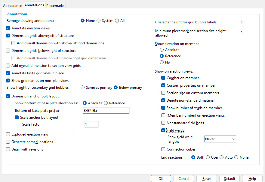
Defaults: Home > Project Settings > Fabricator > Detail Erection View Defaults sets the choices made on this window that are used, by default, when you auto detail an erection view for the first time.

page 1 | contents | process > detail erection views > press "settings" | top


Appearance Annotations Piecemarks

------ Erection view detailing options ------

Remove drawing annotations: None or System or All . This applies when you have already Detailed an erection view once and now want to update it with changes from the 3D model.

Select ' None ' if you want to regenerate only members in the to-be-detailed erection view(s) that you selected to open this window. System-created and user-added annotations will be retained from the last version of the drawing. Warning: If you check this box and check the box for " Annotate erection views, " you will get double system annotations in the resulting erection view drawing.

Select ' System ' if you want to remove all system-created camber annotations, grid lines, elevation annotations, dimensions and grid markers in the to-be-detailed erection view(s). In other words, select ' System ' if you want to retain user-added annotations. User-added annotations that will be retained include objects such as symbols , weld symbols , lines and section views .

Select ' All ' if you want the erection view(s) to be drawn as if they are being detailed for the first time. All user-added drawing layers will be lost, as will any user-added graphics such as sheet items or images or symbols , or user-added lines , or user-added labels , or etc.

Defaults: Home > Project Settings > Fabricator > Detail Erection View Defaults sets the choice (' None ' or ' System ' or ' All ') that is made here by default when you auto detail an erection view for the first time. Changes made on this window are saved with the erection view drawing(s) you selected before pressing " Settings " to open this window but do not affect the window in Fabricator Setup . To repopulate this window with the defaults from Fabricator Setup , you can press the " Default " button.

Annotate erection views: or .

VIDEO " Relative view depth " affects which grid lines and members are shown in an erection view. To get grid lines to show on erection view drawings, the view must be detailed using " Annotate erection views ." (Recorded in SDS2 Detailing , v2015.)

If this box is checked ( ), a label will be generated with the name of the to-be-detailed erection view and/or grid lines will be dimensioned and/or the elevation of a to-be-detailed plan view will be shown (under the erection view's name) and/or the label " C = Denotes camber " will be shown (under the erection view's name). Also: The elevations and names of plan views shown in elevation views will be shown when the box is checked.

If the box is not checked ( ), these extra annotations will not be shown on the to-be-detailed erection views.

Related settings on this window: " Show elevation on member " and " Show grid names on non-plan views " and " Character height for grid bubble labels " and " Show height of secondary grid bubbles " and " Dimension grids above/left of structure " and " Dimension grids below/right of structure " and " Annotate finite grid lines in place " directly affect erection view dimensioning and annotation when the box is checked.

Also see: The erection view type that you assign to erection views in Modeling affects dimensioning.

Tip 1: To annotate an erection view but not to dimension it, turn off (uncheck) the options on this window to " Dimension grids above/left of structure " and " Dimension grids below/right of structure " and keep " Annotate erection views " checked.

Tip 2: To have the annotation " C = Denotes camber " detailed on an erection view drawing, both " Show camber on member " and " Annotate erection views " must be checked (on this window).

Defaults: Home > Project Settings > Fabricator > Detail Erection View Defaults sets the choice ( or ) that is made here by default when you auto detail an erection view for the first time. Changes made on this window are saved with the erection view drawing(s) you selected before pressing " Settings " to open this window but do not affect the window in Fabricator Setup . To repopulate this window with the defaults from Fabricator Setup , you can press the " Default " button.

Dimension grids above/left of structure: or . This option applies when " Annotate erection views " is on (checked). Either choice is compatible with " Annotate finite grid lines in place ."

If this box is checked ( ), then straight grid lines will be dimensioned above and to the left of structural members that appear in the to-be-detailed erection view(s) that you selected to open this window.

If the box is not checked ( ), then dimensions above and to the left of the structure will not be generated in the to-be-detailed erection view(s).

Defaults: Home > Project Settings > Fabricator > Detail Erection View Defaults sets the choice ( or ) that is made here by default when you auto detail an erection view for the first time. Changes made on this window are saved with the erection view drawing(s) you selected before pressing " Settings " to open this window but do not affect the window in Fabricator Setup . To repopulate this window with the defaults from Fabricator Setup , you can press the " Default " button.

Add overall dimension with above/left grid dimensions: or . This applies when " Dimension grids above/left of structure " is on (checked).

The overall dimension in this example is 50-0 , which is the sum of 25-0 and 25-0 . There is no overall dimension on the left side since there are only two grids to be dimensioned on that side.

If this box is checked ( ), then an overall dimension is added where applicable. An overall dimension is applicable when 3 or more grid lines have been dimensioned above or to the left of the depicted structure due to " Dimension grids above/left of structure " having been checked. The overall dimension reports the sum of the dimensions that are above and/or to the left of the structure.

If the box is not checked ( ), an overall dimension is not added.

Defaults: Home > Project Settings > Fabricator > Detail Erection View Defaults sets the choice ( or ) that is made here by default when you auto detail an erection view for the first time. Changes made on this window are saved with the erection view drawing(s) you selected before pressing " Settings " to open this window but do not affect the window in Fabricator Setup . To repopulate this window with the defaults from Fabricator Setup , you can press the " Default " button.

Dimension grids below/right of structure: or . This applies when " Annotate erection views " is on (checked). Either choice is compatible with " Annotate finite grid lines in place ."

If this box is checked ( ), then straight grid lines will be dimensioned below and to the right of structural members that appear in the to-be-detailed erection view(s) that you selected to open this window.

If the box is not checked ( ), then dimensions below and to the right of the structure will not be generated in the to-be-detailed erection view(s).

Defaults: Home > Project Settings > Fabricator > Detail Erection View Defaults sets the choice ( or ) that is made here by default when you auto detail an erection view for the first time. Changes made on this window are saved with the erection view drawing(s) you selected before pressing " Settings " to open this window but do not affect the window in Fabricator Setup . To repopulate this window with the defaults from Fabricator Setup , you can press the " Default " button.

Add overall dimension with below/right grid dimensions: or . This applies when " Dimension grids below/right of structure " is on (checked).

In this example, the overall dimension 50-0 is the sum of the dimensions 25-0 and 25-0 .

If this box is checked ( ), then an overall dimension is added where applicable. An overall dimension is applicable when 3 or more grid lines have been dimensioned below or to the right of the depicted structure due to " Dimension grids below/right of structure " having been checked. The overall dimension reports the sum of the dimensions that are below and/or to the right of the structure.

If the box is not checked ( ), an overall dimension is not added.

Defaults: Home > Project Settings > Fabricator > Detail Erection View Defaults sets the choice ( or ) that is made here by default when you auto detail an erection view for the first time. Changes made on this window are saved with the erection view drawing(s) you selected before pressing " Settings " to open this window but do not affect the window in Fabricator Setup . To repopulate this window with the defaults from Fabricator Setup , you can press the " Default " button.

Add overall dimension to section view grids: or . This applies when " Annotate erection views " is on (checked) and you are detailing an elevation view. An elevation view can be created in Modeling or by using View > Section View in the Drawing Editor .

The overall dimension in this example is 55-0 , which is the sum of 27-6 and 27-6 .

If this box is checked ( ), then an overall dimension is added where applicable. An overall dimension is applicable when 3 or more grid lines have been dimensioned in the elevation view. The overall dimension reports the sum of the dimensions that are below and/or to the right of the structure.

If the box is not checked ( ), an overall dimension is not added.

Defaults: Home > Project Settings > Fabricator > Detail Erection View Defaults sets the choice ( or ) that is made here by default when you auto detail an erection view for the first time. Changes made on this window are saved with the erection view drawing(s) you selected before pressing " Settings " to open this window but do not affect the window in Fabricator Setup . To repopulate this window with the defaults from Fabricator Setup , you can press the " Default " button.

Annotate finite grid lines in place: or . This applies when " Annotate erection views " is on (checked).

VIDEO An erection view depicting a roof frame is auto detailed with "' Annotate finite grid lines in place " turned on, then ' Dimension only ' finite grid lines are added in Modeling and the erection view is auto detailed again. (Recorded in SDS2 Detailing , v2016.)

If this box is checked ( ), then grid lines that are set to " Finite " in Modeling will be drawn similar to the way they are shown in Modeling . This option is compatible with " Dimension grids above/left of structure " and/or " Dimension grids below/right of structure " -- try it , you'll see.

If the box is not checked ( ), finite grid lines will not be drawn in place.

Defaults: Home > Project Settings > Fabricator > Detail Erection View Defaults sets the choice ( or ) that is made here by default when you auto detail an erection view for the first time. Changes made on this window are saved with the erection view drawing(s) you selected before pressing " Settings " to open this window but do not affect the window in Fabricator Setup . To repopulate this window with the defaults from Fabricator Setup , you can press the " Default " button.

Show grid names on non-plan views: or . This applies when " Annotate erection views " is on (checked).

If this box is checked ( ), the names of the erection views will be displayed above the elevations associated with those views.

If the box is not checked ( ), only the elevations of the erection views will be displayed -- not their names.

Defaults: Home > Project Settings > Fabricator > Detail Erection View Defaults sets the choice ( or ) that is made here by default when you auto detail an erection view for the first time. Changes made on this window are saved with the erection view drawing(s) you selected before pressing " Settings " to open this window but do not affect the window in Fabricator Setup . To repopulate this window with the defaults from Fabricator Setup , you can press the " Default " button.

Show height of secondary grid bubbles: Same as primary or Below primary . This applies when " Annotate erection views " is on (checked).

Select ' Same as primary ' if you want the secondary grid markers to be at the same level as the primary grid markers. The actual secondary dimensions (in the example above, 3-0 & 7-0) will continue to be below the primary dimensions.

Select ' Below primary ' if you want the secondary grid markers to be below the primary dimension line (in the example above, the primary dimension line is the 10-0 line).

Defaults: Home > Project Settings > Fabricator > Detail Erection View Defaults sets the choice ( or ) that is made here by default when you auto detail an erection view for the first time. Changes made on this window are saved with the erection view drawing(s) you selected before pressing " Settings " to open this window but do not affect the window in Fabricator Setup . To repopulate this window with the defaults from Fabricator Setup , you can press the " Default " button.

Dimension anchor bolt layout: or . This applies regardless of the choice selected for " Member style ." It does not apply to isometric views . The view being detailed must be a plan view or a partial plan view that shows columns with base plates. Also, the " Hole type " in the base plates must be ' Anchor bolt hole '.

These examples are detailed with ' Wire ' selected with " Show 3D main member material " and " Show 3D holes ."

If this box is checked ( ), the holes in base plates on columns in any plan views that you select to be detailed will be dimensioned.

If the box is not checked ( ), holes in base plates will not be dimensioned on to-be-detailed erection view(s).

Note 1: The box for " Show 3D holes " needs to be checked for holes to be shown -- however, the holes are still dimensioned even if the box is not checked.

Note 2: In order for Detail Erection Views to correctly dimension holes in base plates, the " Hole Type " must be ' Anchor bolt hole '.

Defaults: Home > Project Settings > Fabricator > Detail Erection View Defaults sets the choice ( or ) that is made here by default when you auto detail an erection view for the first time. Changes made on this window are saved with the erection view drawing(s) you selected before pressing " Settings " to open this window but do not affect the window in Fabricator Setup . To repopulate this window with the defaults from Fabricator Setup , you can press the " Default " button.

Also see: Show hidden members

Show bottom of base plate elevation as: Absolute or Reference . This applies when " Dimension anchor bolt layout " is on (checked).

Absolute elevation (37-4) on a partial anchor bolt layout :
Reference elevation (-1-0) on a partial anchor bolt layout :

If ' Absolute ' is selected and " Dimension anchor bolt layout " is on (checked), the resulting drawing notes the true elevation of the bottom surface of each base plate that is at an elevation other than the " Reference Elevation " of the plan view.

If ' Reference ' is selected, the resulting drawing notes the difference between the " Reference Elevation " and the bottom-of-base-plate elevation for each of those same base plates. The value noted is negative (-) if the bottom of the base plate is lower than the elevation of the view.

Defaults: Home > Project Settings > Fabricator > Detail Erection View Defaults sets the choice ( or ) that is made here by default when you auto detail an erection view for the first time. Changes made on this window are saved with the erection view drawing(s) you selected before pressing " Settings " to open this window but do not affect the window in Fabricator Setup . To repopulate this window with the defaults from Fabricator Setup , you can press the " Default " button.

Bottom of base plate prefix: The character string (may include spaces) for noting the elevation of the bottom of base plates on an anchor bolt layout. This prefix is used for each base plate that is at an elevation other than the " Reference Elevation " -- see above . " Dimension anchor bolt layout " must be on (checked) for the prefix to be applied. An explanation of the prefix is provided on the drawing in a note as shown in the example that follows:

Prefix that is entered here :
An explanation of this prefix appears in the note under the drawing name when " Annotate erection views " is checked :
U.N stands for "unless noted." This means that the elevations of base plates whose bottoms are not at 96 feet and 2 inches are noted.

Defaults: Home > Project Settings > Fabricator > Detail Erection View Defaults sets the choice ( or ) that is made here by default when you auto detail an erection view for the first time. Changes made on this window are saved with the erection view drawing(s) you selected before pressing " Settings " to open this window but do not affect the window in Fabricator Setup . To repopulate this window with the defaults from Fabricator Setup , you can press the " Default " button.

Scale anchor bolt layout : or . This applies when " Dimension anchor bolt layout " is on (checked).

" Scale anchor bolt layout " not checked or " Scale factor " = 1:
" Scale anchor bolt layout " is checked and " Scale factor " = 2:

If this box is checked ( ), an anchor bolt layout can be scaled up based on the " Scale factor " that you enter. The centers of columns and the centers of base plates are not affected by the " Scale factor ." Also, dimension labels remain the same. Base plates, hole diameters and column cross sections are depicted per the " Scale factor ."

If the box is not checked ( ), base plates and anchor bolts holes are scaled per the normal " Drawing scale " of the erection view.

Scale factor : A number less than 1 or 1 or a number greater than 1 . This applies when " Scale anchor bolt layout " is checked. The normal " Drawing scale " of the erection view is multiplied by this factor to scale the base plates, their anchor bolt holes, and their columns' cross sections. Dimension labels and other labels remain their same size, and their text is frozen (" Freeze label "). A scale change does not reposition the center of a column or its base plate.

A number less than 1 reduces the size of the base plates, anchor bolt holes and column cross sections by a factor equal to the number entered.

1 gets you the same results that you would get if " Scale anchor bolt layout " were not checked. The difference is that the label text of the anchor bolt dimensions in the new layout is frozen (" Freeze label ").

A number greater than 1 increases the size of the base plates, anchor bolt holes and column cross sections by that factor.

Example: You check the box for " Scale anchor bolt layout " and set the " Scale factor " to 2. In the resulting drawing, the base plates, column cross sections and holes are scaled up to twice their previous size. However, the reported dimensions from the centers of columns to anchor bolt holes remain the same. That is, their dimension " Label text " is the same. Also, that label text is set to frozen (" Freeze label "). If you were to uncheck the box for " Freeze label ," a dimension moved away from then back to the same point would be recalculated to be double its frozen value.

Exploded erection view: or .

If this box is checked ( ), views which show members with defined exploded view positions ( Set in Modeling ) will be detailed so that they depict those members in their exploded positions.

If the box is not checked ( ), members in the to-be-detailed erection views will be shown in their actual (unexploded) locations.

Defaults: Home > Project Settings > Fabricator > Detail Erection View Defaults sets the choice ( or ) that is made here by default when you auto detail an erection view for the first time. Changes made on this window are saved with the erection view drawing(s) you selected before pressing " Settings " to open this window but do not affect the window in Fabricator Setup . To repopulate this window with the defaults from Fabricator Setup , you can press the " Default " button.

Generate named locations: or .

A screen shot of part of an erection view drawing . This is not how the printed drawing would look. The screen shot looks this way because the Mark Named Locations tool caused X's to be shown. Each X marks a named location .

If this box is checked ( ), each resulting erection view drawing will include named locations. These named locations will be invisible unless you use a template development tool such as Mark Named Locations or Nearest Names or Find Property .

If the box is not checked ( ), auto detailing of the erection view(s) will be faster. However, due to higher speeds produced by multi-core detailing, the speed difference may not be obvious.

Defaults: Home > Project Settings > Fabricator > Detail Erection View Defaults sets the choice ( or ) that is made here by default when you auto detail an erection view for the first time. Changes made on this window are saved with the erection view drawing(s) you selected before pressing " Settings " to open this window but do not affect the window in Fabricator Setup . To repopulate this window with the defaults from Fabricator Setup , you can press the " Default " button.

Detail with revisions: This applies to those to-be-detailed erection view(s) that have already been placed on erection sheets. A revision chart is not required for you to get revision information. That information can be maintained in the Sheet Revision Chart Editor without a revision chart. Also, automatic clouding of revision changes can be done without a revision chart.

Drawing: 99-2
is on Sheet: 99-2,
which has revision information.
Original sheet revision: 0
Incremented revision: 1

 
In step 6 of the Detail Erection Views procedure, you will get a message like this one if one of the erection views you detail is on a sheet with revision information.
This revision chart was automatically updated during automatic detailing. Erection view detailing entered the incremented "REV" and the "DATE" because the box for " Locked... " was checked in the revision editor for the sheet that the erection view being detailed was on.
" Detail with revisions " instructs Detail Erection Views to draw clouds (on a revision layer of the erection view drawing) around changes it finds. The character inside the delta symbol indicates the " Sheet revision " level.

If this box is checked ( ), Detail Erection Views clouds changes on the affected erection view drawings by generating the new drawing, then comparing the new drawing with the base drawing , then generating clouds around areas that are different in the new drawing. The clouds and delta symbols are placed on a revision layer which can optionally be printed or not. On the sheet that the erection view drawing appears on, member detailing increments the " Sheet revision " and also adds that revision to the "REV" column of the revision chart along with the "DATE" if the drawing has changed in any way (including a status change) and if the box for " Locked... " is checked in Edit Revision Chart .

If the box is not checked ( ), Detail Erection Views does not add any revision annotations (clouds, etc.) to the detail. It also does not make any changes to the revision chart. Be aware that this does not mean that you can't have a revision chart. It only means that a new line will not automatically be added to that chart during auto detailing.

Steps for automatic revision tracking (one possible procedure):

Cycle 1
1 . " Disable automatic creation of BASE drawings " needs to be turned off in Sheet Revisions setup.
2 . Create a new sheet outline and Revision Chart > Place a revision chart onto it.
3 . Create a new erection sheet using the sheet outline you created.
4 . Detail an erection view and Sheet Items > Add it to the erection sheet that uses the outline you created.
5 . On the new erection sheet, Objects > Revision Chart > Edit , then enter the chart's first line and set it to " Locked... " See the warning below.
6 . Make a change in Modeling that will affect the resulting erection view.
7 . Detail the erection view again, and this time check the box for " Detail with revisions ."
8 . On the erection sheet, you will find that auto detailing clouded the changes to the erection view drawing and added a new revision and date to the revision chart.
Cycle 2
9 . Objects > Revision Chart > Edit the entry that auto detailing made in step 7 above. Set the chart to " Locked... "
10 . Make a change in Modeling that will affect the resulting erection view detail.
11 . Detail the erection view again, and this time check the box for " Detail with revisions ."
12 . On the erection sheet, you will find that auto detailing clouded the changes to the erection view drawing and added a new revision and date to the revision chart.
Note : If " Disable automatic creation of BASE drawings " is turned on, you can still get auto detailing to cloud changes on drawings. However, you will need to manually Create Base Drawing yourself.

delta symbol with a ? inside
Warning : If you don't enter a number or letter to the "REV" cell in the first line of the Sheet Revision Chart Editor before you " Detail with revisions ," Detail Erection Views won't know if it needs to increment the revision using a letter such as A or a number such as 1. The delta symbol will be a "?" instead of a letter or a number. See step 5 in the procedure above.

Defaults: Home > Project Settings > Fabricator > Detail Erection View Defaults sets the choice ( or ) that is made here by default when you auto detail an erection view for the first time. Changes made on this window are saved with the erection view drawing(s) you selected before pressing " Settings " to open this window but do not affect the window in Fabricator Setup . To repopulate this window with the defaults from Fabricator Setup , you can press the " Default " button.

Character height for grid bubble labels: The actual height ( in millimeters ) of grid marker labels. Grid bubbles may be shown when " Annotate erection views " is on (checked) along with " Dimension grids above/left of structure " and/or " Dimension grids below/right of structure " and/or " Annotate finite grid lines in place ."

As you can see in the example above, increasing the character height also increases the diameter of the circles around these labels and the length of the associated dimension extension lines.

Defaults: Home > Project Settings > Fabricator > Detail Erection View Defaults sets the choice ( or ) that is made here by default when you auto detail an erection view for the first time. Changes made on this window are saved with the erection view drawing(s) you selected before pressing " Settings " to open this window but do not affect the window in Fabricator Setup . To repopulate this window with the defaults from Fabricator Setup , you can press the " Default " button.

Minimum piecemark and section size height allowed: The minimum character height ( in millimeters ) of piecemarks and section sizes on drawings when the box is checked for " Check overwriting of piecemarks and section sizes " (on this window). This is also the minimum size that they will be scaled to.

Defaults: Home > Project Settings > Fabricator > Detail Erection View Defaults sets the choice ( or ) that is made here by default when you auto detail an erection view for the first time. Changes made on this window are saved with the erection view drawing(s) you selected before pressing " Settings " to open this window but do not affect the window in Fabricator Setup . To repopulate this window with the defaults from Fabricator Setup , you can press the " Default " button.

Show elevation on member: Absolute or Reference or No . This applies when " Annotate erection views " is on (checked).

Absolute
Reference
No
On plan views , only the elevations of those members whose exact points are at an elevation other than the reference elevation of the plan view will be shown (as in this example). Elevations of all members will be shown on elevation views and isometric views .

If ' Absolute ' is selected, the true elevation of members may be shown on erection view drawings of plan views , elevation views and isometric views . If both ends of the member are at the same elevation and you are using the default Erection View Member Labels setup, the elevation is marked in the middle of the member (unless it would overwrite the section size or camber -- in which case both ends of the member are marked). For a sloping member, the elevation of each of its ends is marked separately.

If ' Reference ' is selected, then members in an erection view drawing of a plan view may be marked with the amount of elevation offset when their exact points are at an elevation other than the reference elevation of the plan view. The offset is marked on each end of sloping members (or on nonsloping beams with camber). The amount of offset is negative (-) if the exact point is lower than the plan view's reference elevation.

If ' No ' is selected, the elevation of member ends that are offset from the reference elevation are not reported on already detailed (or yet-to-be-detailed) erection view drawings. Also, the annotation " Elevation . . . " is not placed on subsequently detailed plan views.

Erection View Cleanup: Left elevation and Right elevation

Disclaimer: The positioning of elevation annotations as described above assumes that the user has not used Home > Project Settings > Fabricator > Erection View Member Labels to change erection view detailing's default behavior with respect to the positioning of elevation annotations.

Defaults: Home > Project Settings > Fabricator > Detail Erection View Defaults sets the choices made on this window that are used, by default, when you auto detail an erection view for the first time.. The choice made for " Show elevation on member " in Fabricator Setup also sets the type of elevation annotation that will be shown in Modeling when " Member end elevations " (in Modeling ) is on.

Camber on member: or . The selection made here affects the display of camber on beams that have camber when those beams are shown.

Camber on member
Camber on member

If this box is checked ( ), then beams with their " Rolling operation " set to ' Camber annotation ' or to ' Camber (Both) ' will have their " Mid-ordinate " value reported as camber on the to-be-detailed erection view(s) that you selected to open this window. Unless the user has specified otherwise in Home > Project Settings > Fabricator > Erection View Member Labels , the camber label is shown at the bottom, center of the beam and causes the section size label to be moved if overwriting would otherwise occur. Checking this option also enables the annotation " C = Denotes camber " to appear on the to-be-detailed erection view(s) when the box for " Annotate erection views " is checked.

If the box is not checked ( ), then the camber of beams will not appear on the to-be-detailed erection view(s). The annotation "C=Denotes camber" will not be placed on those erection views.

Erection View Cleanup: Camber

Defaults: Home > Project Settings > Fabricator > Detail Erection View Defaults sets the choice ( or ) that is made here by default when you auto detail an erection view for the first time. Changes made on this window are saved with the erection view drawing(s) you selected before pressing " Settings " to open this window but do not affect the window in Fabricator Setup . To repopulate this window with the defaults from Fabricator Setup , you can press the " Default " button.

Custom properties on member: or .

Custom properties

Custom properties

If this box is checked ( ), then member custom property values will be shown on appropriate members displayed on the erection view(s) that this window is associated with if you have taken the following steps.

1 (optional) . On the Edit Schema Entry window, check the box for " Add to Erection View Member Labels " for the applicable member schema entry. You can bypass this step and simply type in the " Property name " (instead of selecting it) in step 2.

2 . Select the appropriate " Property name " in Home > Project Settings > Fabricator > Erection View Member Labels and set the location on member stick lines and/or stick cross sections at which you want the custom property label to be applied.

3 . In Modeling , edit for one or multiple members, then press the " Properties " button to open the Edit Properties window. Enter a value for the custom property that you applied a member stick line position for in step 3.

4 . When you Detail Erection Views , press " Settings " and make sure that " Show custom properties on member" is checked ( ) for the erection view(s) that you want the custom property to appear on.

Result: The value you entered in step 3 is printed as a label on members on the erection view drawings generated in step 4.

If the box is not checked ( ), custom properties will not be shown on the to-be-detailed erection view(s) that you selected to open this window.

Schema Add/Edit: Add to Erection View Member Labels (not required)

Setup: Erection View Member Labels (in particular, see " Property name ")

Display Options: Custom properties (display of custom property labels, Modeling )

Erection View Cleanup: Member custom property (display of custom property labels, Drawing Editor )

Defaults: Home > Project Settings > Fabricator > Detail Erection View Defaults sets the choice ( or ) that is made here by default when you auto detail an erection view for the first time. Changes made on this window are saved with the erection view drawing(s) you selected before pressing " Settings " to open this window but do not affect the window in Fabricator Setup . To repopulate this window with the defaults from Fabricator Setup , you can press the " Default " button.

Section size on custom members: or . This applies when the code for the plugin of a custom member includes the GetSectionSize method. If that method has not been appropriately implemented in the plugin, the section size of that custom member will not be able to be displayed.

Section sizes
on custom members


Section sizes
on custom members


The " 14K " section sizes shown in this example are for custom members, BIM joists, which ceased to be distributed in SDS2 programs beginning with v2017.

If this box is checked ( ), then section sizes of custom members that are on erection views will be displayed on the relevant erection view drawings (if the member's " Section size " is tuned on in Erection View Cleanup and the custom member's code includes the GetSectionSize method).

If the box is not checked ( ), then the section sizes of custom members cannot be displayed on erection views whose auto detailing is controlled by this window.

Display Options: " Custom member section sizes " ( Modeling ).

Erection View Cleanup: Section size

Defaults: Home > Project Settings > Fabricator > Detail Erection View Defaults sets the choice ( or ) that is made here by default when you auto detail an erection view for the first time. Changes made on this window are saved with the erection view drawing(s) you selected before pressing " Settings " to open this window but do not affect the window in Fabricator Setup . To repopulate this window with the defaults from Fabricator Setup , you can press the " Default " button.

Denote non-standard material: or . This applies to members whose main material has been assigned a wide flange , plate , tee , channel , angle , pipe or tube steel grade that has a " Nonstandard Notation " entered on its setup table.

Denote ...
Denote ...

If this box is checked ( ), then members on erection views whose auto detailing is controlled by this window are permitted to have a nonstandard notation printed with their section size . Of course, a nonstandard notation must exist in order for it to be printed. A nonstandard notion will exist on members whose " Steel grade " is a grade with a nonstandard notation. A nonstandard notation may be assigned to a steel grade on a material grade window in Job Settings .

If the box is not checked ( ), the nonstandard notation will not be displayed with the section sizes of members on erection views whose auto detailing is controlled by this window.

Erection View Cleanup: Section size

Defaults: Home > Project Settings > Fabricator > Detail Erection View Defaults sets the choices made on this window that are used, by default, when you auto detail an erection view for the first time. The " Denote non-standard material " option in Fabricator Setup also sets whether or not a nonstandard material annotation is shown with a " Section size " in Modeling.

Show number of studs on member: or . This applies to beams on erection view drawings. To get a shear stud count to be shown, you need to enter a " Number of studs " on the Beam Edit window.

Show # ...
Show # ...

If this box is checked ( ) and a " Number of studs " are entered on the Beam Edit window, then Detail Erection Views will include (in parentheses) the number of studs that are entered. The shear stud count will be a part of the section size.

If the box is not checked ( ), the stud count will not be included along with the section size.

Erection View Cleanup: Section size

Defaults: Home > Project Settings > Fabricator > Detail Erection View Defaults sets the choice ( or ) that is made here by default when you auto detail an erection view for the first time. Changes made on this window are saved with the erection view drawing(s) you selected before pressing " Settings " to open this window but do not affect the window in Fabricator Setup . To repopulate this window with the defaults from Fabricator Setup , you can press the " Default " button.

[Member number] on erection views: or .

[Member number] ...


[Member number] ...

If this box is checked ( ), then the erection view detailing program will append [in brackets] the member number for each piecemark that is shown on the to-be-detailed erection view(s) that you selected to open this window.

If the box is not checked ( ), the member number will not be appended to the piecemark..

Erection View Cleanup: Piecemark

Defaults: Home > Project Settings > Fabricator > Detail Erection View Defaults sets the choice ( or ) that is made here by default when you auto detail an erection view for the first time. Changes made on this window are saved with the erection view drawing(s) you selected before pressing " Settings " to open this window but do not affect the window in Fabricator Setup . To repopulate this window with the defaults from Fabricator Setup , you can press the " Default " button.

Non-standard field bolts: or . This applies when appropriate choices have been made to Nonstandard Field Bolts on Erection View Details in Fabricator Setup and non standard field bolts exits in an erection view that your are auto detailing. A field bolt is non-standard when it is not the standard bolt. Bolt Settings sets the standard bolt to be a bolt that is both the standard " Bolt diameter " and the standard " Bolt type ."

Non-standard field bolts


Non-standard field bolts

If this box is checked ( ), non-standard field bolts may be called out on the to-be-detailed erection view(s) that you selected to open this window. Callouts for non-standard field bolts consist of a pointer and either a label or a bolt symbol and can be configured In Home > Project Settings > Fabricator > Nonstandard Field Bolts on Erection View Details . Detail Erection Views finds field bolts of members that are field bolted even when the field bolts themselves are not shown.

If the box is not checked ( ), field bolts are not called out automatically.

Defaults: Home > Project Settings > Fabricator > Detail Erection View Defaults sets the choice ( or ) that is made here by default when you auto detail an erection view for the first time. Changes made on this window are saved with the erection view drawing(s) you selected before pressing " Settings " to open this window but do not affect the window in Fabricator Setup . To repopulate this window with the defaults from Fabricator Setup , you can press the " Default " button.

Field welds: or . This applies to field welds that have been generated during Process and Create Solids . It also applies to field welds that have been user-added in Modeling . Any 3D field weld that exists within an erection view in Modeling can be generated as a weld symbol on a 2D drawing of that erection view. The " Member style " does not affect whether or not field welds can be shown on erection view drawings.

VIDEO

An erection view is auto detailed with " Field welds " turned on and " Show field weld lengths " turned off. The " Settings " button on the Drawing Data window is then used to turn on " Show field weld lengths " for that erection view drawing. The erection view is auto detailed again. (Recorded in SDS2 Detailing , v2018)


Field welds
Field welds
The " Member style " in these examples is ' Wire '. You can also get a weld symbol for ' Stick ' or ' Solid ' or combined styles.

If this box is checked ( ), field welds are called out on the to-be-detailed erection view(s) that you selected to open this window. Callouts for non-standard field bolts consist of one or more pointers and a weld symbol .

If the box is not checked ( ), field welds are not called out automatically.

Note: System connections for which 3D field welds are generated in the model automatically include HSS braces field welded to gusset plates , welded column splices , welded moment connections and shear plates set to be " Attached to " the ' Supported '.

Setup ( Detailing Symbol Settings ): " Combine weld symbols " " Add weld-leader cranks "

Defaults: Home > Project Settings > Fabricator > Detail Erection View Defaults sets the choice ( or ) that is made here by default when you auto detail an erection view for the first time. Changes made on this window are saved with the erection view drawing(s) you selected before pressing " Settings " to open this window but do not affect the window in Fabricator Setup . To repopulate this window with the defaults from Fabricator Setup , you can press the " Default " button.

Show field weld lengths: or . This applies when " Field welds " is turned on (checked).

Show field weld lengths

If this box is checked ( ), weld length will be shown on each field weld symbol that is generated on the to-be-detailed erection view(s) that you selected to open this window.

If the box is not checked ( ), weld length is not shown on the weld symbols.

A similar option for shop welds, Detail Members : The eye button ( or or ) for weld " Length " on the Edit Weld(s) window in Modeling sets whether or not particular welds will have their weld length depicted on their weld symbols when those weld symbols are generated by Detail Members .

Defaults: Home > Project Settings > Fabricator > Detail Erection View Defaults sets the choice ( or ) that is made here by default when you auto detail an erection view for the first time. Changes made on this window are saved with the erection view drawing(s) you selected before pressing " Settings " to open this window but do not affect the window in Fabricator Setup . To repopulate this window with the defaults from Fabricator Setup , you can press the " Default " button.

Connection cubes : or .

... Cubes
... Cubes

If this box is checked ( ), connection cube symbols will be generated for each connection cube that is shown on the to-be-detailed erection view(s) that you selected to open this window.

If the box is not checked ( ), connection cubes will not be shown.

Defaults: Home > Project Settings > Fabricator > Detail Erection View Defaults sets the choice ( or ) that is made here by default when you auto detail an erection view for the first time. Changes made on this window are saved with the erection view drawing(s) you selected before pressing " Settings " to open this window but do not affect the window in Fabricator Setup . To repopulate this window with the defaults from Fabricator Setup , you can press the " Default " button.

End reactions: Both or User or Auto or None .

This shows any end reactions for the member ends on the erection view. If the end reactions are shown, you may see Vertical shear load (Va,v), Horizontal shear load (Va,h), Story shear load (Va,s), Moment load (Ma), Panel zone moment load (Ma,p), Axial loads (Pa), and Tie force (Ty,a). The default nomenclature (shown in paranthesis) can be changed in Erection View Member Labels.

' Both ' results in both end reactions that are user input and have auto checked ( ) (in the Member Edit window) being reported on the erection views.

' User ' results in only those end reactions that have been entered by the user (in the Member Edit window) being reported on the erection views.

' Auto ' results in only those end reactions that have auto checked ( ) (in the Member Edit window) being reported on the erection views.

' None ' results in no end reactions being reported on the erection views.

Defaults: Home > Project Settings > Fabricator > Detail Erection View Defaults sets the choice (' Both ' or ' User ' or ' Auto ' or ' None ') that is made here by default when you auto detail an erection view for the first time. Changes made on this window are saved with the erection view drawing(s) you selected before pressing " Settings " to open this window but do not affect the window in Fabricator Setup . To repopulate this window with the defaults from Fabricator Setup , you can press the " Default " button.

page 1 | contents | process > detail erection views > press "settings" | top


Appearance Annotations Piecemarks

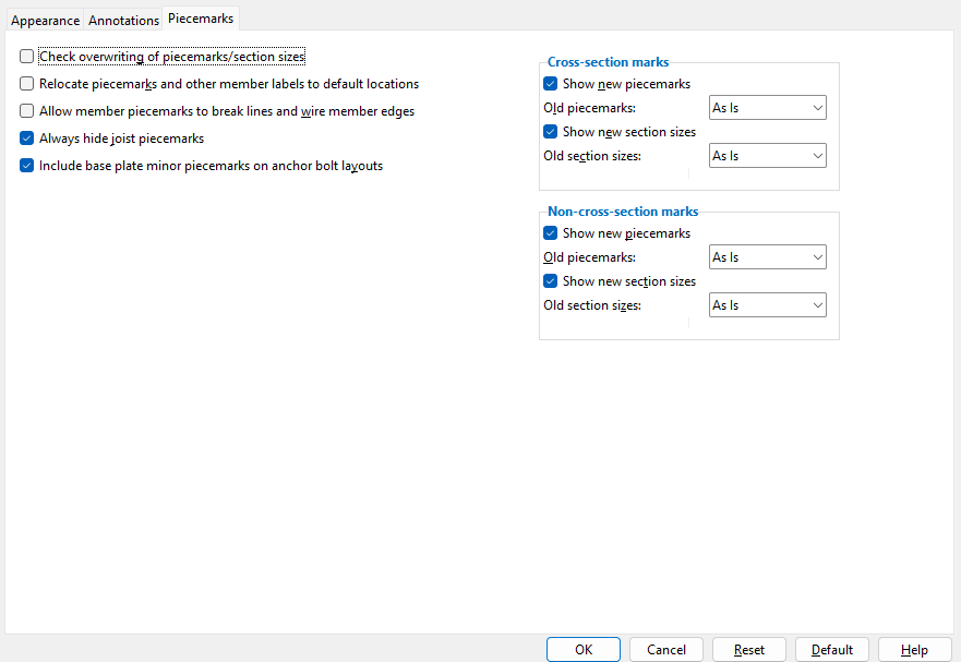
Check overwriting of piecemarks/section sizes: or .

If this box is checked ( ), the auto detailing program will find piecemarks and/or section sizes that overlap and move the marks if possible. If moving the marks does not solve the overwriting, Detail Erection Views will reduce the marks' sizes to no less than the " Minimum mark size allowed ."

If the box is not checked ( ), piecemarks and section sizes will remain in their default locations. You may then want to use Erection View Cleanup operations to manually relocate them yourself.

Defaults: Home > Project Settings > Fabricator > Detail Erection View Defaults sets the choice ( or ) that is made here by default when you auto detail an erection view for the first time. Changes made on this window are saved with the erection view drawing(s) you selected before pressing " Settings " to open this window but do not affect the window in Fabricator Setup . To repopulate this window with the defaults from Fabricator Setup , you can press the " Default " button.

Relocate piecemarks and other member labels to default locations: or . If, in the Drawing Editor , you or other users have not moved any piecemarks and other member labels in the erection views that this window applies to, then it makes no difference whether or not this box is checked.

If this box is checked ( ), then piecemarks, section sizes, camber, left elevation, right elevation, shared elevation and member custom properties that have been relocated in the Drawing Editor (e.g., using Erection View Cleanup ) will automatically be moved back to the location specified in Erection View Member Labels .

If the box is not checked ( ), piecemarks and other member labels that have been relocated in the Drawing Editor will remain in their relocated positions when you detail the erection view(s).

Erection View Cleanup: Piecemark

Note: Changes made to member label locations using Home > Project Settings > Fabricator > Erection View Member Labels will automatically be applied to member labels during automatic detailing of erection views, but not to those labels that were moved (e.g., by dragging them or using Erection View Cleanup ) before the changes were made. If you change settings in Erection View Member Labels and want those settings to be applied to member labels that have been moved, you need to also check this option (" Relocate piecemarks and other member labels to default locations ").

Defaults: Home > Project Settings > Fabricator > Detail Erection View Defaults sets the choice ( or ) that is made here by default when you auto detail an erection view for the first time. Changes made on this window are saved with the erection view drawing(s) you selected before pressing " Settings " to open this window but do not affect the window in Fabricator Setup . To repopulate this window with the defaults from Fabricator Setup , you can press the " Default " button.

Allow member marks to break lines and wire member edges: or .

If this box is checked ( ), a member's piecemark , section size , camber , left end elevation, right end elevation and ABM page-line will be allowed to break lines and wire member edges.

If the box is not checked ( ), piecemarks, section size, camber, left end elevation, right end elevation and page-line numbers will overwrite lines and wire member edges.

Note: To generate members with wire edges, select ' Wire ' or ' Stick+wire ' as the " Steel member style ."

Defaults: Home > Project Settings > Fabricator > Detail Erection View Defaults sets the choice ( or ) that is made here by default when you auto detail an erection view for the first time. Changes made on this window are saved with the erection view drawing(s) you selected before pressing " Settings " to open this window but do not affect the window in Fabricator Setup . To repopulate this window with the defaults from Fabricator Setup , you can press the " Default " button.

Always hide joist piecemarks: or .

If this box is checked ( ), then joist piecemarks will not appear on the erection view(s).

If the box is not checked ( ), joist piecemarks will be allowed to appear on the erection view(s).

Erection View Cleanup: Piecemark

Defaults: Home > Project Settings > Fabricator > Detail Erection View Defaults sets the choice ( or ) that is made here by default when you auto detail an erection view for the first time. Changes made on this window are saved with the erection view drawing(s) you selected before pressing " Settings " to open this window but do not affect the window in Fabricator Setup . To repopulate this window with the defaults from Fabricator Setup , you can press the " Default " button.

Include base plate minor marks on anchor bolt layout: or . This applies when the box is checked for " Dimension anchor bolt layout ,"

Include ...
Include ...

If this box is checked ( ) and the box is checked for " Dimension anchor bolt layout ," auto detailing is instructed to draw an anchor bolt layout that shows the submaterial piecemark on each base plate.

If the box is not checked ( ) during auto detailing of erection views associated with this window, the resulting drawing(s) will not show the submaterial piecemarks of base plates.

Erection View Cleanup: Piecemark

Defaults: Home > Project Settings > Fabricator > Detail Erection View Defaults sets the choice ( or ) that is made here by default when you auto detail an erection view for the first time. Changes made on this window are saved with the erection view drawing(s) you selected before pressing " Settings " to open this window but do not affect the window in Fabricator Setup . To repopulate this window with the defaults from Fabricator Setup , you can press the " Default " button.

------ Cross-section marks ------
( apply to all " Member style " selections )

Show new piecemarks: or . If you are detailing an erection view for the first time, then all cross-section marks are "new." If you are re-detailing a previously detailed erection view, then "new piecemarks" are those piecemarks on the to-be-detailed erection views that do not exist on the current erection view drawing.

If this box is checked ( ), "new" cross-section piecemarks will be shown on the to-be-detailed erection views.

If the box is not checked ( ), "new" cross-section piecemarks will be hidden on the to-be-detailed erection views.

Erection View Cleanup: Piecemark

Defaults: Home > Project Settings > Fabricator > Detail Erection View Defaults sets the choice ( or ) that is made here by default when you auto detail an erection view for the first time. Changes made on this window are saved with the erection view drawing(s) you selected before pressing " Settings " to open this window but do not affect the window in Fabricator Setup . To repopulate this window with the defaults from Fabricator Setup , you can press the " Default " button.

Old piecemarks: Show or Hide or As is . "Old piecemarks" are piecemarks on already detailed erection views that are now to-be-detailed again.

' Show ' causes all "old" cross-section piecemarks to be shown on to-be-detailed erection view(s).

' Hide ' causes all "old" cross-section piecemarks to be hidden on the to-be-detailed erection view(s).

' As is ' causes each cross-section piecemark to be shown or hidden as previously specified by the user (using Erection View Cleanup ) in the Drawing Editor .

Erection View Cleanup: Piecemark

Defaults: Home > Project Settings > Fabricator > Detail Erection View Defaults sets the choice (' Show ' or ' Hide ' or ' As is ') that is made here by default when you auto detail an erection view for the first time. Changes made on this window are saved with the erection view drawing(s) you selected before pressing " Settings " to open this window but do not affect the window in Fabricator Setup . To repopulate this window with the defaults from Fabricator Setup , you can press the " Default " button.

Show new section sizes: or . If you are detailing an erection view for the first time, then all cross-section section sizes are "new." On an erection view that is being re-detailed, new section sizes are those section sizes that are not on the current erection view.

If this box is checked ( ), all "new" cross-section section sizes will be shown on to-be-detailed erection view(s).

If the box is not checked ( ), all "new" cross-section section sizes will be hidden on the to-be-detailed erection view(s).

Erection View Cleanup: Section size

Defaults: Home > Project Settings > Fabricator > Detail Erection View Defaults sets the choice ( or ) that is made here by default when you auto detail an erection view for the first time. Changes made on this window are saved with the erection view drawing(s) you selected before pressing " Settings " to open this window but do not affect the window in Fabricator Setup . To repopulate this window with the defaults from Fabricator Setup , you can press the " Default " button.

Old section sizes: Show or Hide or As is . " Old section sizes " are section sizes on already detailed erection views that are now to-be-detailed again.

' Show ' causes all "old" cross-section section sizes to be shown on to-be-detailed erection view(s).

' Hide ' causes all "old" cross-section section sizes to be hidden on the to-be-detailed erection view(s).

' As is ' causes each cross-section section size to be shown or hidden as previously specified by the user (using Erection View Cleanup ) in the Drawing Editor .

Erection View Cleanup: Section size

Defaults: Home > Project Settings > Fabricator > Detail Erection View Defaults sets the choice (' Show ' or ' Hide ' or ' As is ') that is made here by default when you auto detail an erection view for the first time. Changes made on this window are saved with the erection view drawing(s) you selected before pressing " Settings " to open this window but do not affect the window in Fabricator Setup . To repopulate this window with the defaults from Fabricator Setup , you can press the " Default " button.

------ Non-cross-section marks ------
( apply to all " Member style " selections )

Show new piecemarks: or . If you are detailing an erection view for the first time, then all non cross-section marks are "new." If you are re-detailing an erection view, then " New non cross-section piecemarks " are those piecemarks on the to-be-detailed erection views that are not on the already detailed erection views.

If this box is checked ( ), "new" non cross-section piecemarks will be shown on the to-be-detailed erection views.

If the box is not checked ( ), "new" non cross-section piecemarks will be hidden on the to-be-detailed erection views.

Erection View Cleanup: Piecemark

Defaults: Home > Project Settings > Fabricator > Detail Erection View Defaults sets the choice ( or ) that is made here by default when you auto detail an erection view for the first time. Changes made on this window are saved with the erection view drawing(s) you selected before pressing " Settings " to open this window but do not affect the window in Fabricator Setup . To repopulate this window with the defaults from Fabricator Setup , you can press the " Default " button.

Old piecemarks: Show or Hide or As is . "Old piecemarks" are piecemarks on already detailed erection views that are now to-be-detailed again.

' Show ' causes all "old" non cross-section piecemarks to be shown on to-be-detailed erection view(s).

' Hide ' causes all "old" non cross-section piecemarks to be hidden on the to-be-detailed erection view(s).

' As is ' causes each non cross-section piecemark to be shown or hidden as previously specified by the user (using Erection View Cleanup ) in the Drawing Editor .

Erection View Cleanup: Piecemark

Defaults: Home > Project Settings > Fabricator > Detail Erection View Defaults sets the choice (' Show ' or ' Hide ' or ' As is ') that is made here by default when you auto detail an erection view for the first time. Changes made on this window are saved with the erection view drawing(s) you selected before pressing " Settings " to open this window but do not affect the window in Fabricator Setup . To repopulate this window with the defaults from Fabricator Setup , you can press the " Default " button.

Show new section sizes: or . If you are detailing an erection view for the first time, then all non cross-section section sizes are "new." On an erection view that is being re-detailed, new non cross-section section sizes are those which are not on the already detailed erection view.

If this box is checked ( ), all "new" non cross-section section sizes will be shown on the to-be-detailed erection view(s).

If the box is not checked ( ), all "new" non cross-section section sizes will be hidden on the to-be-detailed erection view(s).

Erection View Cleanup: Section size

Defaults: Home > Project Settings > Fabricator > Detail Erection View Defaults sets the choice ( or ) that is made here by default when you auto detail an erection view for the first time. Changes made on this window are saved with the erection view drawing(s) you selected before pressing " Settings " to open this window but do not affect the window in Fabricator Setup . To repopulate this window with the defaults from Fabricator Setup , you can press the " Default " button.

Old section sizes: Show or Hide or As is . "Old section sizes" are section sizes on already detailed erection views that are now to-be-detailed again.

' Show ' causes all "old" non cross-section section sizes to be shown on to-be-detailed erection view(s).

' Hide ' causes all "old" non cross-section section sizes to be hidden on the to-be-detailed erection view(s).

' As is ' causes each non cross-section section size to be shown or hidden as previously specified by the user (using Erection View Cleanup ) in the Drawing Editor .

Erection View Cleanup: Section size

Defaults: Home > Project Settings > Fabricator > Detail Erection View Defaults sets the choice (' Show ' or ' Hide ' or ' As is ') that is made here by default when you auto detail an erection view for the first time. Changes made on this window are saved with the erection view drawing(s) you selected before pressing " Settings " to open this window but do not affect the window in Fabricator Setup . To repopulate this window with the defaults from Fabricator Setup , you can press the " Default " button.

page 1 | contents | process > detail erection views > press "settings" | top


   To close the Detail Erection View Defaults window :

"OK" (or the Enter key) closes this window. Go to step 2 of Detail Erection Views . In step 2, you choose the erection view(s) that you want to be detailed. The settings that you specified on this window will, when you press " OK ," be stored with whichever erection view(s) you selected before opening this window. This means that the next time you press the " Settings " button to open this window, you will see, on this window, the settings that were last specified for that drawing.

"Cancel" (or the Esc key or the button) closes this window without saving any of the changes that you have made to it.

"Reset" undoes all changes made to this window since you first opened it. The window remains open.

"Default" populates this window with the default settings specified in Home > Project Settings > Fabricator > Detail Erection View Defaults . The window remains open.

page 1 | contents | process > detail erection views > press "settings" | top