Schedule of Minimums for Single-Plate Shear Connections
- General Overview
- Tips and Tricks
- Related Tools
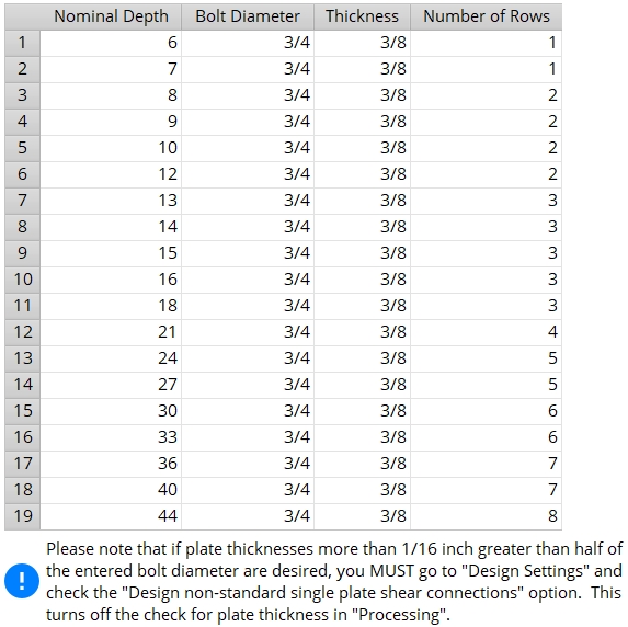
Nominal Depth: The nominal depth of the beam. This applies to beams using wide flange or channel section sizes.
A beam's nominal depth may be different from (although it typically will be close to) the actual depth of the beam. Note: Each section size has a " Nominal depth " associated with it in the local shape file .
Bolt Diameter: The diameter (inches or mm) of the shank of the bolts that attach the shear plate or shear tee or thru plate to the main material of the beam with the particular " Nominal Depth " specified on this row of this table.
diameter 
Effect on connection design: The diameter entered here is the minimum bolt diameter that connection design can use for beam's of the specified nominal depth. Connection design always attempts to use the minimum first.
Thickness: The thickness of shear plate to be used for a beam of particular nominal depth. This applies to single-plate shear connections and thru plates.
Note : For single-plate shear connections, AISC specifies that the plate thickness be less than or equal to one-half the bolt diameter plus 1/16 of an inch. If material that is thicker than this specification is entered to this schedule, then the box for " Design non AISC single-plate shear connections " needs to be checked in order for that material to be applied.
Number of Rows: The minimum number of bolt rows ( 1 to 100 ) that connection design creates for the fastening of the shear plate or tee or thru plate to a beam with the particular " Nominal Depth " specified on this row on the schedule.


|
|
OK (or the Enter key) closes this screen and applies the settings.
Cancel (or the Esc key) closes this screen without saving any changes.
Reset undoes all changes made to this screen since you first opened it. The screen remains open.
- If loading conditions require that a stronger connection be designed, then connection design may increase the bolt diameters or the number of rows.
- Depending on the selected " Connection design method ," connection design may fail shear connections with plate thicknesses more than 1/16 inch greater than half of the bolt diameter unless the box for " Design non-AISC single-plate shear connections " in Design Settings is checked.
- For the " Top of Steel to First Hole " on all types of shear connections, connection design uses the Schedule of Minimums for Structural Members instead of this schedule.
- Red or yellow exclamation point icons
 or
or 
- Standard Shear Plate Settings (additional setup options for shear plates)
- Design non-AISC single-plates (another setup option for shear plates)
- Minimum thickness (moment shear plates, beam splices)
- Setup for shear connections (index)

