 Shapes Properties
The shape file that is selected when this screen opens is the local shape file for your current Job.
- General Overview
- Tips and Tricks
- Related Tools
-
To add a new material to the list, first select the material type, right click and select Add Section. If you have one or more materials selected, right click and select Add Section or Add Section Copy. Selecting Add Section Copy creates an exact copy of the selected section size and all of its values.
-
To delete a material from the list, select one or more cells in the table, right click and select Remove Selected Sections.
Open File: Opens the conf_mtrl folder to allow you to browse to one of the existing shape files. These are used when creating a project.
Browse Jobs: Opens the Select job window so you can edit the shape file of a project other than the one you have open.
Save As: Saves the open shape file with a user assigned name.
New File: Creates a new, empty Shape file.
Copy Shapes: This is used to copy material from one shape file to another.
Filter: As you type in the filter's search field, any section size that contains the text you entered will appear in the list. Click on the section size to automatically browse to the material.
Validation filter:  off
off  on
on
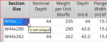
When an entry field in the shape file contains invalid data, warning icons appear next to the affected material type in the Filter's list and on the OK button.
Turn the Validation filter on to display the affected section size(s) in the Filter's list. Select the section size to automatically browse to the material's entry fields and fix the invalid data. Hover your mouse cursor over the warning icon in the entry field to reveal a tooltip explaining its invalid data.
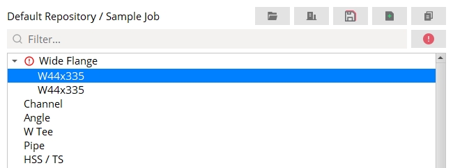
Note: When the Validation filter is enabled, the Filter's search field is disabled.
Material types on this window:
Note 1: You can enter any Section Size name that you like. For example, you can use W or M or HP for section sizes under Wide Flange. Shapes Properties sorts section sizes with the same initial letter together. Modeling in solids form is done per the material type section a section size is under . For example, an S24x100 under the Wide Flange section looks different in Modeling and on drawings than does an S24x100 under the S Shape section.
Note 2: Section sizes of the same type are sorted together per their initial letter (last letter in the alphabet first). For example, W section sizes may be listed first in the Wide Flange section, followed by M then HP section sizes. Sorting for section sizes of the same type is by Nominal Depth (longest first), then Weight per Unit (heaviest first).
Report Writer: MemberMaterial.Material.SubMaterial.MaterialFile.MaterialType
Specifications in the Shapes Properties:
| Material Dimensions |
| Wide Flange || Channel || Angle || Pipe || HSS/TS || W Tee || Joist || Welded Plate Wide Flange || Welded Plate Box || Cold Formed Channel || Cold Formed Z || S Tee || S Shape || Beaded Flat || Round Bar || Clevis || Turnbuckle || Rail |
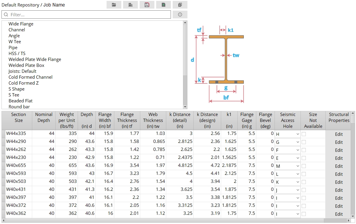
Section Size: The shape designation that conventionally describes the material.
| Naming conventions |
| Wide Flange || Channel || Angle || Pipe || Rail || HSS/TS || W Tee || Joist || Welded Plate Wide Flange || Welded Plate Box || S Tee || S Shape || Cold Formed Channel || Cold Formed Z || Round Bar |
Sorting: Shapes Properties sorts sections with the same initial letters together.
Nominal Depth: This is usually the depth as reported in the section size of the material, though it does not have to be. For example, in the default USA shape file, W18x35, W18x40, W18x65 section sizes all have a nominal depth of 18. Nominal depth may or may not be the actual measured Depth of the channel , pipe , W tee , S tee , S shape or wide flange material.
Nominal depth is used to reference specific section sizes in the Schedule of Minimums for Structural Members , the Schedule of Minimums for Single-Plate Shear Connections and the table for Channel splice section size selection .
For wide flange and channel beams, executing Con Lines Thru Material generates a construction line on the beam web at half of the material's nominal depth.
Weight per Unit (lbs/ft or kg/m): The pounds per foot or kilograms per meter along the longitudinal axis (X material axis) of the material.
This value is used in SDS2 to calculate the actual weights of submaterials and members, so it is important that any value you enter here be accurate.
Moment of Inertia (ix): See Structural Properties.
General Information: Moment of inertia (ix) is one of a number of Structural Properties that may be stored in a shape file. The ix value represents the resistance of material to flexure and torsion. Connection design uses the ix value to, for example, calculate the Moment load when
Auto is selected for that field on the Beam Edit window.
Cross-sectional area: This applies to joist material only. This is the cross-sectional area of the joist, not including the joist diagonals. For a typical joist, this will be the cross-sectional area of the top and bottom chords. The information entered here is not used by SDS2.
k distance (detail) (mm or inches): The distance from the outside face of the flange to the toe of the web fillet on an angle, channel, W tee, S tee, wide flange, or S shape section.
| k = k distance |
|
SDS2 uses this distance for clearance checks to ensure that materials fit together at the construction site. Members in any of the three solid forms and member details will show this distance.
The k distance (detail) is based on the maximum fillet radius as determined from a survey of mills. The default USA shape file ( /.../conf_mtrl/SDS2/usa_mtrl) lists only a few wide flange sections whose k distance (detail) and k distance (design) are different. It does not list any channel or angle sections whose design and detail k distance are different.
Example: Connection design uses the k distance (detail) that is set in the local shape file along with the Maximum amount of allowable k infringement that is entered in Connection Detailing and Fabricator Options to ensure that a connection to a beam web does not impinge too far on the fillet radius.
k distance (design) (mm or inches): Same as k distance (detail), except that this distance is used in connection design. Angle sections do not have an entry field for k distance (design).
| k = k distance |
|
For design and verification purposes, it is the minimum fillet radius that is of interest, and therefore the k distance (design) may, for some sections, be smaller than the k distance (detail).
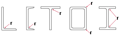
Radius: The distance that defines the amount of curvature of the corners of an angle, channel, W tee, wide flange, or HSS/TS section.
| r = radius |
|
Note: This radius will be applied to the material in the model and reflected consistently across all drawings.
Flange Bevel: The number of degrees that the flange slants on a channel, S shape, S tee, wide flange, or W tee section. Channel, S shape, and S tee shapes are given a Flange Bevel of 9.462 in the default USA shape file. Most wide flange and W tee sections have a Flange Bevel of 0 and therefore are not illustrated in the examples shown below.
| b = flange bevel |
|
Capacity: The nominal strength (Rn) of the clevis or turnbuckle. The value is expressed in kips. Connection design of rod bracing uses this Capacity for evaluating the load-carrying capacity of the clevis or turnbuckle. Rod bracing is designed when the user enters a round bar material as a vertical brace Section size.
Rod brace connection failure message: Clevis/turnbuckle/clevis pin size failure
Rod brace connection failure message: Suitable turnbuckle capacity not found
Rod brace connection failure message: Suitable clevis capacity not found
|
If this box
If the box
is not checked, the section size will appear on the list that you can open with the
file browse button. Also, you can manually type in the section size without getting a warning.
Source Reference: The source shape file that this material originated from. You can change this source (for this material only) by typing in a different source name.
| shape file | SDS2 location | source reference |
| default USA | /conf_mtrl/SDS2/usa_mtrl | SDS2 Pre 7.0 USA |
| default Canadian | /conf_mtrl/SDS2/can_mtrl | SDS2 Pre 7.0 Can |
| default all | /conf_mtrl/SDS2/all_mtr | SDS2 Pre 7.0 All |
Example: You Copy a material from the default Canadian shape file to your local shape file. Later you start up Shapes Properties and look at that material. The Source reference for that particular material will read: SDS2 Pre 7.0 Can.
Seismic Access Hole: None or A or B or C or D or E or F or G or H or I or J or K or L or M. This applies to wide flange material only.
You don't have to manually fill these out yourself: The default USA and default all shape files are both filled out with the appropriate letter designation (A or B or etc.) per Table 1-2 in the AISC Seismic Design Manual. As long as your local shape file is a copy of one of these shape files (because it was entered as the Shape file source when you started your current Job), your Job will be properly set up for the design of a welded moment Seismic ... connection.
How this information is used: The letters (A, B, C, etc.) that may be selected here are also referenced at Home > Project Settings > Job > Seismic Weld Access Holes. When you apply a welded moment Seismic ... connection on a beam with a wide flange Section size with a particular Seismic Access Hole designated in the local shape file, connection design looks at the Seismic Weld Access Holes setup window to determine the size and shape of that access hole. If None is selected here, then connection design does not reference the Seismic Weld Access Hole Configurations setup window, but instead uses the setup values defined for moment connections in Weld Design Settings.
Structural Properties: For a C12x30 section in a usa_mtrl file, if you press the Edit button under the Structural Properties column, a window like that shown below will open. One example of a Structural Property is moment of inertia (ix) . Many Structural Properties are tabulated values which are stored in certain shape files. For shape files that do not have tabulated values stored in them, SDS2 uses the calculated Formula values.
|
This example shows the Structural Properties for a C12x30 section. The values reported in the white column are editable. They are values tabulated from the AISC. The values reported in the Formula column are calculated values. Connection design prefers to use the tabulated values (if they exist). If tabulated values do not exist, connection design uses the calculated Formula values. |
| Tabulated Structural Properties values can be found in the following shape files: usa_mtrl, can_mtrl, all_mtrl, AISC_14thEd_1stPrint, AISC_ASTM_A1085, CISC_10thEd_4thPrint. The |
|
| If you change a shape file specification such as the Depth of a material, the Formula structural properties will be recalculated, but the tabulated values will stay the same, since they are tied to the Section Size. | |
Structural Properties for an HSS 9.625 x 0.500 (an HSS round section):
HSS round sections such as the HSS 9.625 x 0.500 in the example above are found under the Pipe section in Shapes Properties. They can take steel grades that are specified on the Pipe Grades window. The column ASTM A501 appears in the above example (taken from Shapes Properties) because a Production Standard of that name was entered on the Pipe Grades window. The ASTM A1085 and ASTM A500 columns in this example have tabulated values (book values), which are stored in Shapes Properties. The ASTM A501 column has Formula values, which are calculated, not stored The Wall thickness for an HSS 9.625 x 0.500 is 0.5 inch. Since a Production Standard called ASTM A1085 was applied to a steel grade on the Pipe Grades window, the Design Thickness that will be applied when that steel grade is used for an HSS 9.625 x 0.500 section will be 0.5 inch. For an HSS 9.625 x 0.500 with a steel grade using the ASTM A500 or ASTM A501 standard shown in this example, the Design Thickness used would be 0.465 inch.
Structural Properties for an HSS 8 x 6 x 1/2 (an HSS rectangular section):
HSS rectangular sections such as the HSS 8 x 6 x 1/2 in the example above are found under the HSS/TS section in Shapes Properties. They can take the steel grades specified on the HSS / TS Grades window. The column BOGUS 50 appears in the above example (taken from Shapes Properties) because a Production Standard of that name was entered on the HSS / TS Grades window. The ASTM A1085 and ASTM A500 columns in this example have tabulated values (book values), which are stored in Shapes Properties. The BOGUS 50 column only has calculated Formula values, which are calculated, not stored. The Wall thickness for an HSS 8 x 6 x 1/2 is 0.5 inch. Since a Production Standard called ASTM A1085 was applied to a steel grade on the HSS / TS Grades window, the Design Thickness that would be applied if that steel grade were used for an HSS 8 x 6 x 1/2 section would be 0.5 inch. As shown in the example above, an HSS 8 x 6 x 1/2 with a steel grade using the ASTM A500 production standard, the Design Thickness used would be 0.465 inch. For an HSS 8 x 6 x 1/2 with a steel grade using the BOGUS 50 production standard, the Design Thickness used would be 0.25 inch.
OK (or the Enter key) closes this screen and applies the settings.
Cancel (or the Esc key) closes this screen without saving any changes.
Reset undoes all changes made to this screen since you first opened it. The screen remains open.
- Red or yellow exclamation point icons
 or
or 
- Files that are located in conf_mtrl/SDS2/ are the default shape files. These files automatically update when you install a new version of SDS2. Do not edit these files.
- Copy Shapes in Utility Functions can be used to copy material from one shape file to another. It's usually easier and more accurate to Copy Shapes than it is to add it manually.

