The Standard End Plates window ( Fabricator Settings )
| Settings on this window are read-only . They tell you how this window has been set up for the Master Fabricator in a full-featured SDS2 program . |
Also see :
- Standard piecemarks (topic)
- Connection design (automatically uses standard piecemarks where appropriate)
page 1 | contents | home > project settings > fabricator > piecemarking >
A special requirement: Your current Fabricator needs to be the Master Fabricator in order for you to use the following methods to open this window.
Method 1 : Home > Project Settings > Fabricator > Piecemarking > Standard End Plates .
page 1 | contents | home > project settings > fabricator > piecemarking > | top
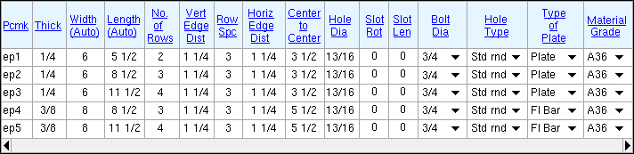
Columns on the Standard End Plates window :
Piecemark: The standard submaterial mark (up to 61 characters) that a full-featured SDS2 program assigns to non-moment end plates whose description matches the entries to this line.
Thickness: The distance (in the primary dimension " Units " or other units ) between the two faces of the plate that have the largest surface area.
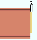
t = thickness of end plate. Setup: The " Minimum thickness " for end plates is set on the End Plate Settings window. If connection design is set to " Use the miscellaneous plates list " when designing end plates, any thickness that is entered here should match a thickness that is in the " Plate Thicknesses " list under the " End Plates " tab on the Plates setup window.
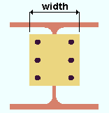
Width: The width of the end plate is automatically calculated from the " Horizontal Edge Distance " and the " Center to Center " hole distance.
Length: The length of the end plate is automatically calculated from the " Vertical Edge Distance ," " Row Spacing " and " No. of Rows ."
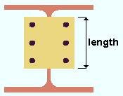
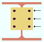
No. of Rows: The number of rows of holes in the end plate. Bolt rows run parallel with the flanges of the supported beam.
|
No. of Rows = ' 3 '. |
Tip: Since an end plate has two hole columns, the number of rows on the end plate is equal to one half of the total number of holes.
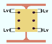
Vertical Edge Distance: The vertical distance (in the primary dimension " Units " or other units ) from the horizontal edge (top or bottom) of the end plate to the center of the nearest hole.
|
Lv = vertical edge distance. |
Setup: Connection design uses the " Vertical edge distance " that is set in End Plate Settings .
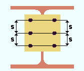
Row Spacing: The vertical distance (in the primary dimension " Units " or other units ) between the centers of any two adjacent rows of holes in the plate.
|
s = row spacing. |
Setup: Connection design uses the " Bolt spacing " that is set for the bolt diameter, in Connection Detailing/Fabricator Options .
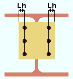
Horizontal Edge Distance: The horizontal distance (in the primary dimension " Units " or other units ) from the vertical edge of the plate to the center of the nearest hole.
|
Lh = horizontal edge distance. |
Setup: Connection design uses the " Horizontal edge distance " in End Plate Settings .
Center to Center: The distance (in the primary dimension " Units " or other units ) between the centers of the columns of holes on the plate.
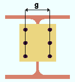
|
g = center-to-center between columns of holes. |
Setup: Connection design uses the " Center to center holes, wide gage " or the " Center to center holes, narrow gage " in End Plate Settings .
Hole Diameter: The diameter of holes (in the appropriate " Units " or other units ) that are in the end plate.
| From TABLE J3.3, AISC Thirteenth Edition , p16.1-105 | ||||
|
Bolt
Diameter |
Standard (Dia.) |
Oversized (Dia.) |
Short-Slot
(Width) |
Long-Slot
(Width) |
| 1/2 | 9/16 | 5/8 | 9/16 | 9/16 |
| 5/8 | 11/16 | 13/16 | 11/16 | 11/16 |
| 3/4 | 13/16 | 15/16 | 13/16 | 13/16 |
| 7/8 | 15/16 | 1 1/16 | 15/16 | 15/16 |
| 1 | 1 1/16 | 1 1/4 | 1 1/16 | 1 1/16 |
| 1 1/8 or > | d + 1/16 | d + 5/16 | d + 1/16 | d + 1/16 |
| From TABLE J3.3M, AISC Thirteenth Edition , p16.1-105 | ||||
|
Bolt
Diameter |
Standard (mm) |
Oversized (mm) |
Short-Slot
(mm) |
Long-Slot
(mm) |
| M16 | 18 | 20 | 18 | 18 |
| M20 | 22 | 24 | 22 | 22 |
| M22 | 24 | 28 | 24 | 24 |
| M24 | 27 | 30 | 27 | 27 |
| M27 | 30 | 35 | 30 | 30 |
| M30 | 33 | 38 | 33 | 33 |
| M36 or > | d + 3 | d + 8 | d + 3 | d + 3 |
Setup: Connection design sets the hole diameters (width for slots) based on the hole type and the bolt diameter (see the above tables). It uses the " Standard hole type " on the End Plates Setup window. For non-moment end plates that are not auto standard, it uses the " NM bolt diameter " on the Beam Edit window. For auto standard end plates, it uses the " NM bolt diameter " on the Auto Standard Connections window.
Slot rotation: A positive or negative value from 90 to -90 degrees. This applies when the " Hole type " is ' Long slot ' or ' Short slot '. Slot rotations can be modeled to a precision of 0.1 degree.
![]()
Slot length: The distance (in the primary dimension " Units " or other units ) between the two points farthest from one another on the perimeter of a slot. This applies when the " Hole type " is ' Long slot ' or ' Short slot '.
| slot length |
|
|
Bolt diameter: The diameter (inches or mm) of the shank of the bolt to be used for connecting the end plate to the supporting member.
| diameter |
|
Hole Type: Standard round or Short slot or Long slot or Oversized round .

Setup: Connection design uses the " Standard hole type " in End Plates Setup for holes in end plates.
Type of Plate: Plate or Flat Bar .
' Plate ' should be selected if no listing on the Preferred Flat Bar Sizes window matches the " Thickness " and " Width " that is entered for this line on this window.
' Flat Bar ' should be selected if the Preferred Flat Bar Sizes window does have a listing that matches the " Thickness " and " Width " that is entered for this line on this window.
Setup: Plate material is used for end plates unless there is a suitable flat bar listed on the Preferred Flat Bar Sizes window.
Material Grade: Any steel grade from Home > Project Settings > Job > Plate Grades . These same steel grades appear in Flat Bar Grades . It does not matter if the " Type of Plate " is a ' Plate ' or a ' Flat Bar '.
Setup: To have as many end plates as possible assigned the " Piecemark " defined on this line, the grade selected here should probably be the " Plate material grade " that is set under the " End Plates " tab on the Plates window. The grade under that tab is used when the " End plate grade " for a connection is set to "
Auto ."
page 1 | contents | home > project settings > fabricator > piecemarking > | top