The End Plate Settings setup window ( Fabricator Settings ) (read-only)
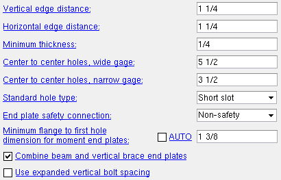
In a full-featured SDS2 program , the settings you can review on this window work in coordination with individual end plate connection specificatons to determine connection design when the " Input connection type ' on the Beam Review window is ' End plate ' or ' Auto standard ' or ' User defined '.
Also see :
- End plate input specs (settings for defining end plates)
- Location (setting for defining a moment end plate)
- Bolt pattern (setting for defining a moment end plate)
- Setup of end plates (various related Job/Fabricator Settings )
home > project settings > fabricator > standard fabricator connections > | classic | top
Method 1 : Home > Project Settings > Fabricator > Standard Fabricator Connections > End Plate Settings .
home > project settings > fabricator > standard fabricator connections > | classic | top
| Note: In a full-featured SDS2 program , end plate connection design checks the " Preferred Flat Bar Sizes " list for available bar stock material. If appropriate material is found, the program uses that flat bar and takes into account the rolled edge when setting the " Horizontal edge distance ." If no appropriate material is found, the program designs a plate with the edge distance recommended in Table J3.4 or J3.4M, AISC Thirteenth Edition , p16.1-107 or 1 1/4 inch (whichever value is greater). |
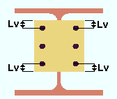
Vertical edge distance: The minimum vertical distance (in the primary dimension " Units " or in other units ) from the horizontal edge (top or bottom) of the end plate to the center of the nearest hole.
|
Lv = vertical edge distance. |
Effect on a full-featured SDS2 program: The minimum vertical edge distance shown here applies in a full-featured SDS2 program to the connection design of end plates. The actual designed vertical edge distance may be greater than the distance shown here.
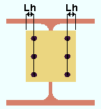
Horizontal edge distance: The minimum horizontal distance (in the appropriate " Units ") from the edge of the plate to the center of the nearest hole (see illustration).
|
Lh = horizontal edge distance. |
Effect on a full-featured SDS2 program: The minimum horizontal edge distance shown here applies in a full-featured SDS2 program to the connection design of end plates. The actual horizontal edge distance may be greater than the distance shown here. This setting does not apply to flat bar "end plate" connections, which use sections from the Preferred Flat Bar Sizes setup window and apply the minimum edge distance at rolled edges as specified in the third column of Table J3.4 or Table J3.4M (p16.1-107) in the ASD/LRFD 13th edition and in other design codes . Connection design uses the Schedule of Minimums for Structural Members to determine the number and spacing of holes on end plates.
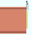
Minimum thickness: The minimum thickness (in the primary dimension " Units " or in other units ) of end plates that a full-featured SDS2 program will use when designing end plate connections.
|
t = thickness of end plate. |
Effect on a full-featured SDS2 program: The minimum thickness shown here applies (in a full-featured SDS2 program , not in Site Planning) to the connection design of end plates. Connection design will use thicker plate material than is shown here if such material is needed to meet AISC guidelines and structural loading criteria.
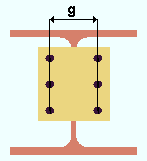
Center to center holes, wide gage: The distance (in the primary dimension " Units " or in other units ) from the center of the column of holes on one side of the web of the supported beam to the column of holes on the other side of the web (see illustration). This distance should be between 5 1/2 and 7 1/2 inches in order for an end plate to be designed.
|
g = gage (center-to-center between columns of holes). |
Effect on a full-featured SDS2 program: The gage shown here applies to the design of an end plates when " Wide Gage " has been specified for that end plate.
Center to center holes, narrow gage: The distance (in the primary dimension " Units " or in other units ) from the center of the column of holes on one side of the web of the supported beam to the column of holes on the other side of the web (see illustration).

|
g = gage (center-to-center between columns of holes). |
Effect on A full-featured SDS2 program: The gage shown here will be applied to the design of an end plate if " Narrow Gage " has been specified user for that end plate.
Standard hole type: Standard round or Short slot or Long slot or Oversized round or User Slot #1 or User Slot #2 .
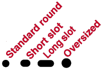
Effect on a full-featured SDS2 program: The hole type shown here applies (in a full-featured SDS2 program , not in Site Planning) during Process and Create Solids to the design of holes in end plates. Connection design determines the specific size and shape of the holes on the end plate according to the hole type that is shown here and the diameter of bolt that is used.
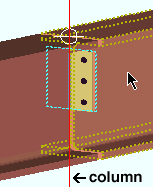
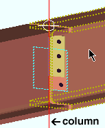
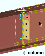
End plate safety connection: Non-safety or Safety-offset or Safety-notch . This applies when two beams with end plates frame to opposite sides of a supporting column web (or a beam web). In such a framing situation, the end plates on the two beams will share bolts.
|
|
|
||||||
| The wide flange column in these illustrations is in stick form ( red ) so that its flange does not cover the end plates that frame to its web. The right beam's end plate is outlined in blue . | ||||||||
' Non-safety ' instructs connection design to create the two end plates so that they share all bolts when " Safety connection " is set to ' Automatic ' on the Beam Review window.
If ' Safety-offset ' is selected and " Safety connection " is set to ' Automatic ' on the Beam Review window, connection design is instructed to vertically offset the end plates with respect to one another so that one row of bolts is not shared by the end plate of the opposing beam.
If ' Safety-notch ' is selected and " Safety connection " is set to ' Automatic ' on the Beam Review window, connection design is instructed to design deeper end plates to accommodate an extra row of bolts and to perform a " Cope " on each plate so that each bolt in the top row of bolts is shared by the column and a different beam. The cut to the plate will be on the far side of the beam that has its end plate specified on its left end ; the plate cut will be on the near side of the other beam (which will have the end plate on its right end).
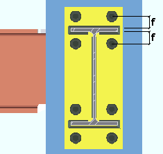
Minimum flange to first hole dimension for moment end plates: Auto or a user-entered dimension . The " Flange to first hole dimension " is from the center of the hole to the nearest face of the flange (top or bottom face, whichever is closer).
|
f = flange to first hole. |
If " Auto " is checked (
), connection design calculates this dimension as the bolt diameter plus 1/2 inch (12.7 mm) plus the flange weld " Weld size " if the flange weld is a fillet weld. If the flange weld is a groove weld with a reinforcement fillet weld, the reinforcement weld size will be used instead of the flange weld (minimum 1st hole dimension = bolt dia + 0.5 inch + reinforcement fillet weld size).
If " Auto " is not checked (
) and a ' distance ' is entered here, connection design uses that distance in its design of the moment end plate only if the distance is greater than the minimum first hole distance. The minimum first hole distance is the value used when "
Auto " is checked.
Combine beam and vertical brace end plates: ![]() or
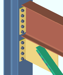
or ![]() . For an angle , W tee or channel vertical brace framing to a beam and column, connection design will create an end plate for the gusset-to-column interface if the beam connects to the column with an end plate. This field tells you what the user of a full-featured SDS2 program has applied as the default for whether or not the end plates will be combined into a single end plate.
. For an angle , W tee or channel vertical brace framing to a beam and column, connection design will create an end plate for the gusset-to-column interface if the beam connects to the column with an end plate. This field tells you what the user of a full-featured SDS2 program has applied as the default for whether or not the end plates will be combined into a single end plate.
|
|
If this box is checked (
) and ' Automatic ' is selected for " Combine beam/vbr end plates ," connection design will create a single end plate to connect both the beam and vertical brace gusset plate to the column.
If the box is not checked (
) and ' Automatic ' is selected for " Combine beam/vbr end plates , connection design will create two separate end plates, one to connect the beam to the column, the other to connect the vertical brace gusset plate to the column.
Use expanded vertical bolt spacing: ![]() or
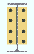
or ![]() . This applies when ' Automatic ' is the choice made to " Use expanded vertical bolt spacing " (on the Beam Review window) for a particular ' Non-moment ' end plate connection.
. This applies when ' Automatic ' is the choice made to " Use expanded vertical bolt spacing " (on the Beam Review window) for a particular ' Non-moment ' end plate connection.
 |
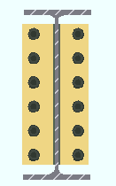 |
If this box is checked (
), connection design in a full-featured SDS2 program will to expand the vertical spacing of bolts to 1.5 times or 2 times the " Bolt spacing " that is set for the bolt diameter in Connection Detailing/Fabricator Options . The program may also adjust to a spacing other than 1.5 or 2 times the standard bolt spacing in order to accommodate piecemarking issues, loading conditions and unusual geometries.
If the box is not checked (
), , connection design in a full-featured SDS2 program will use the " Bolt spacing " that is set for the diameter of bolts that is used in the end plate connection.
A possible application: When an axial load (" Tension " or " Compression ") has been entered on the end of a beam with an end plate connection, expanded vertical bolt spacing can promote uniform loading across the connection bolts.
Another application: Expanded vertical hole spacing can also help to reduce fabrication costs by minimizing the number of rows of bolts in end plates.
home > project settings > fabricator > standard fabricator connections > | classic | top
