 Material Drafting ( Drawing Editor )
Tool summary :
Also see :
- Shorten limit line (place material with respect to)
- Member Isolation (alternative way to add views to details)
- Add Standard Detail (alternative way to add views to details)
- Comment layer (on most drawings, the drawing of the material is added to this type of layer)
- Crane placement drawings (drawing type on which you can add items to non-comment layers)
page 1 | contents | tools > | tools
Example :
Material Drafting can be used to add a top view, bottom view, section view or elevation view of a material.
page 1 | contents | tools > | tools | top
Step-by-step instructions :
The following instructions assume that you are using a 4-button mouse.
1 . Invoke Material Drafting using any one (1) of the following methods:
Method 1 : Click the Material Drafting icon. The icon can be taken from the group named ' Tools ' and placed on a toolbar (classic) or the ribbon (lightning).
Method 2 : If " Drawing Editor layout style " is ' Classic ', you can use the menu system to choose Tools > Material Drafting .
Method 3, 4 or 5 : Material Drafting can also be invoked using a keyboard shortcut , the context menu , or a mode . For the ' Lightning ' layout style, configuration of the interface is done using Customize Interface .
2 . The Material Drafting window opens. On it are the following options:
------ Material information ------
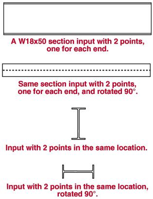
Material: Any section size listed the local shape file (e.g. W18x50). Also, you can enter rectangular plate (e.g. PL3/8x1-0) and flat bar (e.g. FL3/8x1-0), even though these materials are not included in the local shape file. The program does not draw joist section sizes since a joist's actual appearance depends on the manufacturer.
To enter a section : You can type in the section size you want, or you can press the browse button (
) and double-click any section that is on the list of available materials in the local shape file .
Rotation: Any positive or negative (-) angle from 360 to -360 degrees to rotate the material from horizontal (' 0 ' is horizontal). This only applies when ' Section ' is the " View ."
Length: Select ' From points ' if you want the program to measure the length of the material from the points you will input in step 4. Or select ' Material length ' and type in the distance that you want (in the primary dimension " Units " or in other units ). The length that is entered here directly affects the proportions that the section is drawn to.
View: Select ' Section ' if you want a cross-sectional view of the material. Select ' Elevation ' if you want an elevation view of the material. Please note that if you select ' Elevation ', you must in step 4 designate two points at different locations to define the longitudinal axis of the section.
Centering: Select ' Center ' to cause the to-be-added material to be centered over the line you will input in step 4. Select ' Offset ' to cause the material to be offset above or to the right of the line you will input in step 4.
Mirroring: Select ' Mirror image ' to bring the material drawing in as a mirror image of itself. A mirror image is one in which right and left are reversed. Select ' Normal ' to bring the image into your current drawing file in its standard orientation. Mirroring is only relevant for nonsymmetrical sections such as angles.
|
|
| Press the button corresponding to the line type you want to draw the material with. |
Pen number: 1 or 2 or 3 or 4 or 5 or 6 or 7 .

The button that is pressed sets the printing pen number (and also the on-screen display color) of the material. Defaults for Line Weights set printers to draw graphic objects using black lines of specified width. Layer: Any drawing layer (any layer given a " Name ") in your current drawing. This is the layer the material will be drawn on after you press " OK " to close this window. If that layer happens to be hidden (not " Shown "), the material will disappear after the first Redraw . If your current drawing is not a crane placement drawing, non-comment layers on the selection menu for this field will be grayed out. The default selection (
) for this field is the layer that was selected on the layer selection tool before you began this operation.
![]()
![]()
Alternative 1 : Press the " OK " button to continue. Go on to step 3.
Alternative 2 : Press the " Cancel " button to end the Material Drafting operation.
3 . Various Locate options become active, and the status line prompts, "Locate end of material."
3a (optional) : click the Locate icon that you want (if it's not selected already).
3b : Position your mouse pointer (
) so that the point location target (
) snaps to where you want one end of the material and left-click ( Locate ).
4 . Go to step 5 if you selected ' Section ' as the " View ." Otherwise, the status line prompts, "Locate second point."
4a (optional) : Click the Locate icon that you want (if it's not selected already).
4b : Position your mouse pointer (
Note 1: If you locate this second point at the same location as the point located in step 3, you get a cross-sectional view (even if you selected ' Elevation ' as the " View ").
Note 2: If you place this second point at a different location than the point located in step 3 and you selected ' Elevation ' as the " View ", then the line between these two points sets the longitudinal axis of the material. If you selected ' From Points ' for " Length ," then these two points set the actual length of the material.
5 . Locate - +90/-90 - Return mouse bindings become active.
Alternative 1 : Rotate the drawing of the material by clicking +90 or -90 , then left-click ( Locate ) to make the material's position permanent. Go on to step 6.
Alternative 2 : Right-click ( Return ) to go back to step 3 to place the view of the material again.
6 . Locate - Repeat - Return mouse bindings become active. Do one (1) of the following.
Alternative 1 : Follow these instructions beginning with step 3 to input different drawings of the same material designated in step 2.
Alternative 2 : Move your mouse pointer (
Alternative 3 : Right-click ( Return ) if you don't want to add any extra drawings of the material.