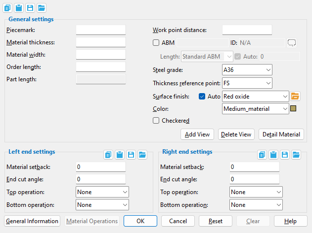
The Rectangular Plate Material window ( Modeling ) (read-only)
Settings on this window are the choices applied to this material using a full-featured SDS2 program . Together with the work points defined when the material was added, these settings fully define the material in the model. Plate material sections are not defined in the local shape file .
Piecemark: The submaterial piecemark (up to 61 characters) for the rectangular plate whose settings you are reviewing.
Also see: Rectangular plate system piecemarks begin with the material mark prefix for " Plate ." For the quantity of rectangular plates that have been assigned this piecemark, refer to the " Current quantity " listed for this material on its General Information window.
Material thickness: The thickness of this plate (in the primary dimension " Units " or in other units or the gage ). This dimension is measured along the material's Z axis .
Gage plate: If, for example, ' 4GA ' is entered here, then this is a gage plate. Allowable gages are any whole number from 3 to 38 . The " Description " for a gage plate follows the format: ' plate type prefix ' + ' numberGA ' + ' x ' + ' width ' (example: PL16GAx15 1/2 ).
Note: How thickness is measured with respect to the elevation is determined by the " Thickness reference point ."
Material width: The width (in the primary dimension " Units " or in other units ) of the rectangular plate being added/edited. This dimension is measured along the plate's Y material axis and will be the same on both its left and right ends. A rectangular plate's width may be longer than its " Material length ."
Order length: The distance measured before end cuts are made (in the primary dimension " Units " or in other units ) from the furthest point on the material's left endto the furthest point on the material's right end. This dimension is measured parallel with the material's longitudinal axis ( X material axis ).
Note: The longitudinal axis of a user-added material is established by how that user added work points. The first point located establishes the material reference point .
Part length: The distance parallel with the X axis of the plate from the furthest point on the plate's left end to the furthest point on the plate's right end. Unlike the " Order length ," this distance is measured after end cuts are made. In most cases, the " Part length " and " Order length " will be exactly the same. One special cases is described below:
The " Part length " and " Order length " are different due to the combination of an " End cut angle " and a " Cope " on the plate.
Work point distance: The distance (in the primary dimension " Units " or in other units ) between the work points of this rectangular plate.
Note: The " Material length " of the rectangular plate will be different from the " Work point distance " if the ends of the plate are cut at an angle (as shown above).
Steel grade: Any grade of steel ( A36 or A572 or etc.) from Steel Grades for Plates & Bar Stock table in Job Options may be shown here as the steel grade for this plate.
Thickness reference point: FS or Center or NS . ' NS ' stands for near side, ' FS ' for far side.
' Center '
' FS '
' NS '
A section view of the same rectangular plate , but with different depth reference points. The view looks perpendicular to the plan view (at 100 ft) in which the rectangular plate was added.
' NS ' sets the near side of the plate at the elevation of the plate's work points.
' Center ' centers the plate's thickness at the elevation of the plate's work points.
' FS ' sets the far side of the plate at the elevation of the plate's work points.
Note: This option does not affect the plate's reference elevation. It positions the plate with respect to that reference elevation.
Surface finish: None or Sandblasted or Red oxide or Yellow zinc or Gray oxide or Blued steel or Galvanized or Duplex Coating or Undefined 1 or Undefined 2 or Undefined 3 or Red oxide 2 or Any user added surface finish. This affects the colors of 'Solid ' members on erection views in the Drawing Editor . This also sets the color when "Output material color " is set to 'Surface finish ' for a VRML Export or a DWG/DXF Export . The "Color " ( not "Surface finish ") sets the color of this material in Modeling .
sand blasted
red oxide
yellow zinc
user surface finish 1
gray oxide
blued steel
galvanized
user surface finish 2
To assign a different surface finish, you can drop-down the current surface finish and select the one you want, or you can press the "file cabinet" browse button ( ) and double-click any surface finish that is on the list.
Auto or .
If this box is checked ( ), the material surface finish follows what is set on the member level.
If the box is not checked ( ), the material surface finish can be changed to whatever is available in the list of surface finishes. If the surface finish changes from what the member level has set, the auto checkbox will be unchecked automatically. When the auto check box is unchecked, the member edit window shows an information tag which notifies the user that an attached material is not following what was set on the member level.
Note 1:Submaterial piecemarkscan be split apart by surface finish. All surface finishes that do not have the 'Break Marks Material' checked on can be applied to any like material with out the material splitting. If the 'Break Marks Material' is checked on then only like materials with that specific surface finish can have the same piecemark, and because the submaterial marks differ so would the member's piecemark.
Note 2:When exporting a KISS file using "model" as the "Data source " surface finish data on the materials are compiled into the KISS download as follows, with a few exceptions (G=galvanized, N= none or sandblasted, P= others). Those exceptions are:
If the box for "Finish" routing in KISS export setup is set to a user routing
If the user has adjusted the Abbreviation for any of the default provided surface finishes
If you are using a user added surface finish
In these cases you will get what is provided in either the User routing, or the abbreviation field. For other exports it will always provide the abbreviation in the 'surface finishes' settings page.
Tip 1: "Surface area" is reported on the General Information window -- and this can be used to estimate the amount of coating required and its cost.
Tip 2: Changing "Steel grade " "Color " and "Surface finish " do not cause the plate to be regenerated. This means that, if you change those settings only, material fit operations such as a Fit Exact may, optionally, be preserved.
Color: The color of the rectangular plate when it is displayed in a solid form . Different colors may be assigned to materials that have the same submaterial piecemark . The color swatch next to the list box ( ) displays the color that is selected.
Setup: The default colors for member main materials and submaterials is set up on the Modeling Colors setup window.
Checkered: or .
If this box is checked ( ), this rectangular plate is a checkered plate, which is a steel plate with raised ribs on its near-side surface to prevent slippage on items such as floors and stair treads. The " Material thickness " of a checkered plate is measured exclusive of the raised pattern. The prefix set for " Checkered " in Member and Material Piecemarking is added to the " Description " on the General Information window and in the member bill of material (for example, PL 3/8x10 becomes CHKD PL 3/8x10 when ' CHKD ' is the " Description " in setup). In a full-featured SDS2 program , the plate will be detailed on the submaterial and the member with a small sample of the checkered pattern.
If the box is not checked ( ), the rectangular plate is considered to have a smooth near-side surface.
Material setback: The positive or negative (-) distance in the primary dimensioning " Units " that the (left or right) end of the rectangular plate is displaced from its work point. A negative material setback makes the rectangular plate longer; a positive material setback makes it shorter.
Note: If the plate has a left/right " End cut angle " of ' 0 ' degrees (which makes it rectangular), the " Material setback " distance is subtracted from the " Work point distance " to give you the actual " Material length ."
End cut angle: Any positive or negative (-) angle greater from 90 to -90 degrees. The angle will be cut along the Y material axis (the width) of the plate.
An angle of ' 0 ' degrees causes the end of the rectangular plate to be square cut.
Assuming that you are viewing the near side of the rectangular plate, a ' positive angle ' is measured counterclockwise from a perpendicular bisector to the workline. A ' negative angle ' is measured clockwise from a perpendicular bisector to the workline.
' None ' designates that no top/bottom cutting operation be performed on this rectangular plate.
' Cope ' designates a 90 degree (L-shaped) cut with a rounded corner.
' Length ' sets the length of the cope along the longitudinal axis (X material axis) from the left/right end of the plate.
' Width ' sets the width of the cope (Y material axis) from the top/bottom of the plate toward its center.
' Clip ' designates a single, linear cut.
A special case: The left end, " Bottom length " allows a negative entry when there is a negative " End cut angle ."
' Length ' sets the length of the clip along the longitudinal axis from the left/right end of the plate. This distance can be negative in the special case shown above (for a shear plate on a sloping welded moment connection).
' Width ' sets the width of the cope from the top/bottom of the plate in toward the plate's center.

) and double-click any surface finish that is on the list.
), the material surface finish follows what is set on the member level.
), the material surface finish can be changed to whatever is available in the list of surface finishes. If the surface finish changes from what the member level has set, the auto checkbox will be unchecked automatically. When the auto check box is unchecked, the member edit window shows an information tag which notifies the user that an attached material is not following what was set on the member level.