The Beam Template Editor ( Job Settings )
- A template that you create/edit in the Beam Template Editor window can be entered to " Template " on the Concrete Beam Edit window.
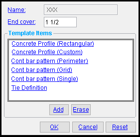 |
To open this window, double-click a template on the Beam Templates window, or on that same window select a template and press " Edit " or press " Add ." One " Template item " (a concrete profile) should always be shown. To add an item to that profile, press the " Add " button. To delete an item, select it and press the " Erase " button. Select a " Template Items " to edit that item. |
-
 opens a window with a list of template items that you can add to the " Template items " list shown above. In order to select " Tie ," you need to first have a bar pattern already on the list of " Template Items ."
Grid cont bar pattern
Perimeter cont bar pattern
Single cont bar pattern
Tie

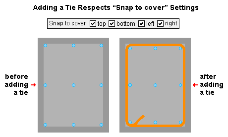
After pressing " Add " then selecting " Tie ," you select the item's shape (its picture), then you are prompted to select the perimeter reinforcing bars that you want the tie to constrain. It is permissible to select the same bar twice. The dimensions of the tie are based on the bars that you select.
-
 deletes the item on the " Template Items " list that you have selected. Be aware that you cannot delete a concrete profile. The " Erase " button is disabled -- grayed out -- when the item selected under " Template Items " is a concrete profile. See " Profile ."
concrete | beam templates | top
" Name " and " End Cover " :
Name: Read only or Blank . The name of the concrete beam template that you are adding or editing.
If " Name " is read-only , this is the name of the " Template " that you selected on the Beam Templates window when you opened this window. It is the name of the template that you are editing.
If " Name " is blank , then you pressed " Add " to open this window, You must type a " Name " in order to complete the creation of the new template.
Tip: If you want to change the name of a template, you can create a template exactly like that template but with the new name that you want by selecting that template (on the Grade Beam Templates window, not this window) then pressing " Save As ."
End cover: The distance (in the primary dimension " Units " or other units ) from the end of the rebar to the left or right end of the concrete beam.

|
| An elevation view of a concrete beam. The " End cover " distance sets back the reinforcing bars from both the left end and right end of the concrete beam. |
The following options can be found in various " Template Items " :
Profile: Rectangular or Custom . This applies when the item selected on the " Templates item " list is a profile. A concrete profile viewed in the Beam Template Editor shows a perspective from the left end of the concrete beam. A concrete beam's left end is established by the 1st work point that was located when that member was added.
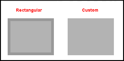
' Rectangular ' gives you options for defining a rectangular or square concrete profile, including a cover. See " Concrete Profile (Rectangular) ."
' Custom ' gives you options for a concrete profile that is a shape that you define by pressing " Edit ." There are no options for defining a cover. See " Concrete Profile (Custom) ."
Rebar size: Any size that has been entered to the Rebar Definitions Setup window under the " Active rebar standard " can be selected here.
Standard: Any standard that has been entered to the Rebar Specifications window can be selected here.
A " Standard " must be selected for a " Cont bar pattern (grid) " or " Cont bar pattern (single) " or " Cont bar pattern (perimeter) " or " Tie definition "
User configuration: If a standard that you want is not available, you can add that standard on the Rebar Specifications window.
Steel grade: Any steel grade that is available in the " Standard " that you have selected can be selected here.
A " Steel grade " must be selected for a " Cont bar pattern (grid) " or " Cont bar pattern (single) " or " Cont bar pattern (perimeter) " or " Tie definition "
User configuration: If a steel grade is not available for selection, selecting a different " Standard " will make that steel grade available if the steel grade you want is in that other standard. If you don't want to change to a different " Standard ," you can open the Rebar Specifications window and add the steel grade you want to the standard that you currently have selected.
Coating: None or a Coating that is available in the " Standard " that you have selected. A " Coating " can be selected for a " Cont bar pattern (grid) " or " Cont bar pattern (single) " or " Cont bar pattern (perimeter) " or " Tie definition "
Select ' None ' if you do not want a coating. Since it is possible to create standards that do not have coatings, it is possible that ' None ' may be your only option.
User configuration: If a coating is not available for selection, selecting a different " Standard " will make that coating available if the coating you want is in that other standard. If you don't want to change to a different " Standard ," you can open the Rebar Specifications window and add the coating you want to the standard that you currently have selected.
Function: Any usage description from the " Beam " section of the Rebar Usage Descriptions window. The " Function " that you enter here is used on the schedules that appear on drawings.
User configuration: To add a " Function " that you can select here, you can type that function to the " Beam " section of the Rebar Usage Descriptions window.
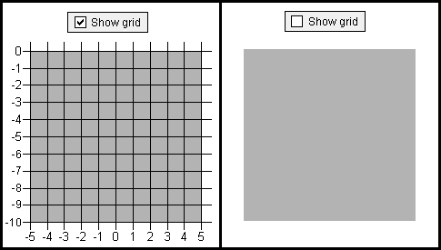
When this box is checked (
), a grid with X-axis and Y-axis rulers overlays the depiction of the template.
When the box is not checked (
), the template is depicted without the grid overlay.
concrete | beam templates | top
------ Concrete Profile (Rectangular) ------
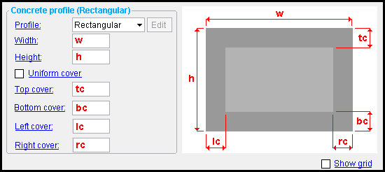
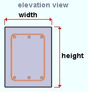
Width: A distance (in the primary dimension " Units " or other units ). When a concrete beam in Modeling that has this template's " Name " entered to " Template " on its Concrete Beam Edit window, then the " Width " entered here is the actual cross-sectional width of that concrete beam.
|
In Modeling , the " Width " of the concrete beam's cross section is horizontal across your computer screen if you are looking at an elevation view of either end of the member. |
Height: A distance (in the primary dimension " Units " or other units ). When a concrete beam in Modeling that has this template's " Name " entered to " Template " on its Concrete Beam Edit window, then the " Height " entered here is the actual cross-sectional height of that concrete beam.

|
In Modeling , the " Height " of the concrete beam's cross section is vertical across your computer screen if you are looking at an elevation view of either end of the member. |
When this box is checked (
), the value you enter to " Top cover " also applies to the bottom, left and right cover.
When the box is not checked (
), you are permitted to enter different concrete thicknesses for the " Top cover " " Bottom cover " " Left cover " and " Right cover ."
Top cover: The concrete thickness (in the primary dimension " Units " or other units ) of the grade beam's top cover.
Bottom cover: The concrete thickness (in the primary dimension " Units " or other units ) of the grade beam's bottom cover.
Left cover: The concrete thickness (in the primary dimension " Units " or other units ) of the grade beam's left cover.
Right cover: The concrete thickness (in the primary dimension " Units " or other units ) of the grade beam's right cover.
concrete | beam templates | top
------ Concrete Profile (Custom) ------

|
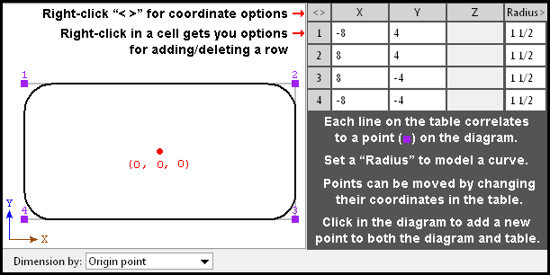
| When the " Profile " is set to ' Custom ', pressing the " Edit " button opens the Co ncrete Profile window, which you can use to edit the concrete profile as described below. |
|
Radius: A distance (in the primary dimension " Units " or other units ) that defines the amount of corner rounding that takes place.
The " Radius " is the radius of a circle. Two lines that are tangent to that circle meet at the located point. The corner's arc ends at the points of tangency of these two lines. 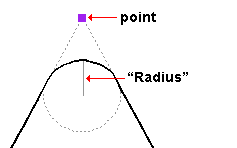
A " Radius " of ' 0 ' designates a sharp corner with no corner rounding.
Increasing the size of the " Radius " moves the edge of the rounded corner back from the corner point. This is because the " Radius " defines a circle that is tangent to both lines to the corner point. The arc of the rounded corner begins and ends at the tangent points.
You can set a different " Radius " for each corner. Clicking on the upper-right corner of the table (" Radius > ") lets you set the radius for each point to be the same value.
Dimension by: Length and angle or Previous point or Origin point . This applies when you hover a point in the diagram with your mouse pointer ( ![]() ), regardless of whether or not you are adding points.
), regardless of whether or not you are adding points.
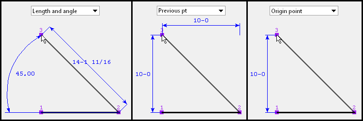
' Length and angle ' shows one or two dimensions and an angle. The dimension(s) are to the point you are hovering. One dimension may be to the previous point, and another dimension may be to the next point. The angle to the point you are hovering may be the included angle between the hovered point and the previous two points. Or it may be the angle between the hovered point and a horizontal or vertical bisector to the previous point.
' Previous point ' shows horizontal and/or vertical dimensions between the point you are hovering and the previous point in the diagram. Dimensions of zero will not be shown.
' Origin point ' shows horizontal and/or vertical dimensions from the origin point (point 1) to the point you are hovering. Dimensions of zero will not be shown.
Adding points: You can click a line in the diagram to add a point. The new point snaps to your mouse pointer until you left-click to locate that point or right-click to cancel. Dimensions are shown as you move your mouse pointer to reposition the snapped-to point. An alternative to clicking in the diagram to add points is to enter the points to the table.
concrete | beam templates | top
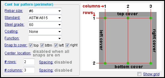
------ Continuous bar pattern (Perimeter) ------
concrete | beam templates | top
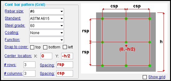
------ Continuous bar pattern (Grid) ------
Snap to cover: A Top and/or Bottom and/or Left and/or Right perimeter constraint to the pattern. The option applies when the concrete profile is rectangular. The option is disabled ( grayed out ) when the " Profile " is ' Custom '. Be aware that when bars snap to the cover the initial placement of those bars is readjusted to compensate for the thickness of the tie when you " Add " a tie.
Top:
or
. When "
Top " is checked, the top row of continuous bars in the grid is constrained to the top cover and the " Center location, Y " is disabled and, in effect, zero. If "
Top " is not checked, the position of the top row can be manipulated using " Row spacing ."
Bottom:
or
. When "
Bottom " is checked, the bottom row of continuous bars in the grid is constrained to the bottom cover. Note that if both "
Bottom " and "
Top " are checked, then the position or all rows is fixed and you cannot change either the " Center location, Y " or the " Row spacing ."
Left:
or
. When "
Left " is checked, the left column of continuous bars in the grid is constrained to the left cover and the " Center location, X " is disabled and, in effect, zero. If "
Left " is not checked, the position of the left column can be manipulated using " Column spacing ."
Right:
or
. When "
Right " is checked, the right column of continuous bars in the grid is constrained to the right cover. Note that if both "
Right " and "
Left " are checked, then the position or all columns is fixed and you cannot change either the " Center location, X " or the " Column spacing ."
Tip: Since " Row spacing " and " Columns spacing " are center-to-center spacings, the math needed to calculate how to use those options to place continuous bars flush with the cover could be tedious. Its usually easier to use these snaps and let the Beam Template Editor calculate the needed spacing for you.
Center location: An X distance and a Y distance from the center, top of the concrete profile. Distances can be entered in the primary dimension " Units " or other units .
"X" is the X distance and can be positive or negative. A value of 0 aligns the horizontal center of the pattern at the center of the concrete profile. Entering a negative X distance moves the horizontal center of the pattern that distance to the left. Entering a positive X distance moves the horizontal center of the pattern that distance to the right.
"Y" is the Y distance and can be positive or negative. A value of 0 aligns the vertical center of the pattern with the top of the concrete profile. A value of -h/2 aligns the vertical center of the pattern at the center of the profile, where h is the " Height " of a rectangular profile. Entering a negative Y distance moves the vertical center of the pattern down. Entering a positive Y distance moves the vertical center of the pattern up.
# rows: The total count (an integer) of continuous bar rows in the grid pattern. Rows run horizontally in the pattern. The " Spacing " between rows runs vertically.
Spacing (rows): The center-to-center distance between rows of continuous bars in the grid pattern. Rows run horizontally in the pattern. The " Spacing " between rows runs vertically.
# columns: The total count (an integer) of continuous bar columns in the grid pattern. Columns run vertically in the pattern. The " Spacing " between columns runs horizontally.
Spacing (columns): The center-to-center distance between columns of continuous bars in the grid pattern. Columns run vertically in the pattern. The " Spacing " between columns runs horizontally.
concrete | beam templates | top
------ Continuous bar pattern (Single) ------
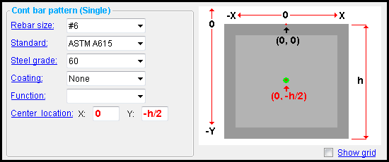
Center location: An X distance and a Y distance from the center, top of the concrete profile. Distances can be entered in the primary dimension " Units " or other units .
"X" is the X distance and can be positive or negative. A value of 0 centers the continuous bar at the horizontal center of the concrete profile. Entering a negative X distance moves the continuous bar that distance to the left. Entering a positive X distance moves the continuous bar that distance to the right.
"Y" is the Y distance and can be positive or negative. A value of 0 aligns the vertical center of the pattern with the top of the concrete profile. A value of -h/2 aligns the vertical center of the pattern at the center of the concrete profile, where h is the " Height " of a rectangular profile. Entering a negative Y distance moves the continuous bar down. Entering a positive Y distance moves the continuous bar up.
concrete | beam templates | top
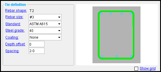
This is the tie definition shape that you selected after you pressed " Add " and selected " Tie ."
To change this shape, you need to select this " Template item " then press " Erase " then press " Add " and select " Tie " and then select a different shape.
concrete | beam templates | top
To close/reset the Beam Template Editor :
"OK" (or the Enter key) closes the Beam Template Editor and reactivates the Beam Templates window. The template edited using this window will be saved to the Job Settings file in your current Job . To apply template changes to a beam that uses that template in the model, you can mark for processing that beam then Process and Create Solids .
"Cancel" (or the Esc key or the
button) closes this window without saving any changes made to it.
"Reset" undoes all changes made to this window since you first opened it. The window remains open.
Also see :
- Beam Templates (the Beam Templates Editor is opened from)
- Concrete Beam Edit (window for editing concrete beams in Modeling )


