Detail View Area
- General Overview
- Tips and Tricks
- Related Tools
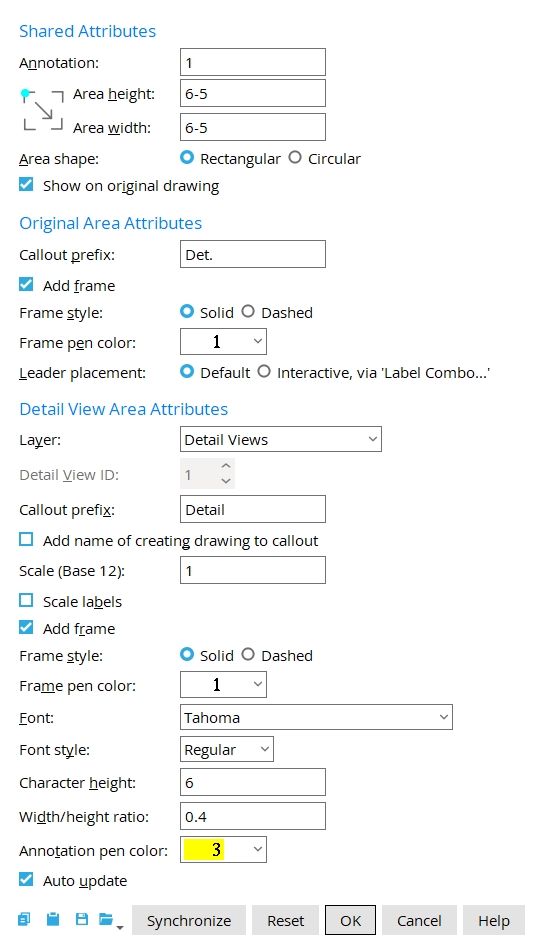
Shared Attributes
Annotation: A unique text string that must be filled out. The text that is entered here is combined with each of the two Callout prefixes into two labels, one for the original area and the other for the detail view area. See Callout prefix for the original area, Callout prefix for the detail view area. The annotation is also used for the file name.
|
Two portions of a member detail are shown in this example. The left side represents the original area, while the right side shows the detail view area. The Callout prefix for the original area is Det. of, and for the detail view area it is Detail of. The Annotation is a52. |
Note: If you open this window after a detail view has been created changing the Annotation text string changes the detail view file name.
Area height: The height of the rectangular area that you defined on the original drawing when you added the detail view. Changing the area height can alter the extents of the image that are shown in the detail view, and can only be done while the view is being created. To edit the viewport after it has been created, open the Detail View Drawing and adjust it there.
Area width: The width of the rectangular area that you defined on the original drawing when you added the detail view. Changing the area width can alter the extents of the image that are shown in the detail view, and can only be done while the view is being created. To edit the viewport after it has been created, open the Detail View Drawing and adjust it there.
Area shape: Rectangular or Circular. This selects the shape of the frame displayed within the original area rectangle that you designated when you added the detail view. It affects both the original area and the detail view area. After the viewport has been created, this cannot be changed.
Show on original drawing: ![]() or
or ![]() .
.
If this box
is checked, the detail view area is shown on the creating drawing.
If this box
is not checked, the detail view area is not shown on the creating drawing. However, its callout remains visible around the original area in the drawing. To place a detail view drawing onto a sheet or other drawing is to use Sheet Item Add and check Detail Views.
Original Area Attributes
Callout prefix: blank or a character string that precedes the Annotation. The Annotation and the Callout prefix are combined in the label that designates the original area. The default character string is Det..
If this box
If this box
Frame style: Solid or Dashed. This is the linetype of the callout frame displayed around the original area. This setting only applies if Add frame ![]() is checked.
is checked.
|
|
If
Solid is selected, the frame is made up of solid lines.
If
Frame pen color: 1-7. Select the printing pen number (and on-screen display color) of the frame.
Leader placement: Default or Interactive, via Label Combo. This setting is enabled only when you first Add the detail view. The option will be disabled ( grayed out ), when you Edit the detail view.
When
When
Detail View Area Attributes
Layer: The drawing layer that the detail view you are adding or editing is placed onto when you press OK to close this window. If that layer happens to be hidden (not marked Show), the detail view disappears after an update.
Defaults: For an Add Detail View operation, the default selection (
) will be the layer Detail Views.
Detail View ID: Read only. The view's number , which is unique within the drawing that you edit.
Callout prefix: blank or a character string that precedes the Annotation. The Annotation and the Callout prefix are combined in the label that designates the detail view area. The default character string is Detail.
Add name of creating detail to callout: ![]() or
or ![]() . The choice made here does not affect the file name of the detail view. It affects the view's callout only.
. The choice made here does not affect the file name of the detail view. It affects the view's callout only.
|
If this box
If this box
Scale (Base 12 or Base 10): The scale you want applied to the detail view area. This scale also becomes the Drawing scale of the detail view drawing that is created in order to create the detail view area. Depending on your choice of Units , the scale is either base 12 or base 10. The default scale that is shown here when you are adding a new detail view to a drawing for the first time is the Scale of the drawing that you are adding the detail view to.
(Base 12) means Imperial dimensioning is being used. Enter the number of inches on your current drawing that you want to represent 1 foot in the shop or construction site.
(Base 10) indicates Metric dimensioning is being used. Enter the number of millimeters on your current drawing that you want to represent 10 mm on the actual materials.
If this box
If this box
If this box
If this box
Frame style: Solid or Dashed. This applies when ![]() Add frame is checked. It sets the line type of the frame displayed around the detail view area.
Add frame is checked. It sets the line type of the frame displayed around the detail view area.
When
When
Frame pen color: 1 or 2 or 3 or 4 or 5 or 6 or 7. This sets the on-screen display color of the frame. No button is pressed if you are editing multiple detail views that have different pen numbers.
Font: Any font that is listed can be selected for the detail view.
|
For a TrueType font , such as any of those shown here, set the Width/height ratio to 0.6 to have the font rendered at its native width. |
Font style: The style ( Bold or Bold Italic or Italic or Regular ) of the selected Font. Different fonts may have different styles available to them.
Character height: The font size ( in millimeters ) of the callout label of the detail view area. This value is independent of the Drawing scale of this drawing. Assuming that the sheet that this drawing will eventually be placed on has a scale of 1:1 and you do not re-scale the detail and the printer does not adjust the scale, this will be the actual height of characters on the plotted sheet.
|
Font dependencies: This applies to whatever font is selected as the detail view Font , regardless of whether that font is a TrueType font or the SDS2 font.
Width/height ratio: The width/height of the characters that make up the make up the callout label of the detail view area.
|
Annotation pen color: 1 or 2 or 3 or 4 or 5 or 6 or 7. No color is selected if you are editing multiple detail views that have different pen numbers.
For a TrueType font, the Pen affects the display color of the text while you are in the Drawing Editor , but does not affect the plotted appearance of the Font so long as all pens in Line Weights are set to print in black.
For the SDS2 Font, the pen color sets the stroke weight (thickness) of the detail view characters. Line Weights assigns a particular thickness to each Pen.
Auto update: ![]() or
or ![]() . This affects the detail view. When the creating detail is auto detailed, the original area is updated to match the model regardless of the choice made here.
. This affects the detail view. When the creating detail is auto detailed, the original area is updated to match the model regardless of the choice made here.
If this box
If this box
Tip: If this is a problem, you can press the Synchronize button to update the detail view area.
Synchronize: applies changes made in the creating drawing to the detail view.
Reset: undoes all changes that you have made in to the Detail View Area window since it was opened. The window remains open.
OK (or Enter ) closes this window and completes the operation.
Cancel (or the Esc key or the ![]() button) closes this window without saving changes you have made.
button) closes this window without saving changes you have made.
Defaults: The settings on this window do not become the defaults for new detail views if you press Cancel to close this window.
- Detail view drawing
- Detail View Add
- Open Detail View Drawing
- Detail Views (a downloadable HOW/2.pdf file)

