 Selection Mode ( Drawing Editor - for preselection )
Tool summary :
Also see :
- Drag and Drop Configuration (controls points snapped to when dragging objects)
- Aperture (also affects points snapped to when dragging certain objects)
- Use mouse wheel ( User Options > the " Interface " tab > )
- Select Item(s) (similar mode for in-tool selection)
- Select One Item (similar mode for in-tool selection)
- Lasso Mode (alternative mode for preselection)
page 1 | contents | selection | drawing editor | top
 Step-by-step instructions :
Select Items is designed for pre-tool selection. First you select items, then you activate the tool that acts on the items. Related modes -- Select Item(s) and Select One Item -- are for in-tool selection (which happens when you start up a tool without having first made an appropriate pre-tool selection).
1 . To activate Select Items mode, use any of the following methods:
Method 1 : Launch the Drawing Editor . Select Items mode mouse bindings are activated automatically.
Method 2 : Click the icon. In classic, the icon can be found on a toolbar. In lightning, the ribbon editor.
Method 3 : Use Mode Return to pop out of your current mode and back into Select Items mode.
2 . While in Select Items mode, the following mouse bindings are available for a 3-button mouse.
- Select (left-click)
- Double-click (left-click)
- Pan (hold down the middle button)
- Menu (right-click to open the context menu)
- Select+ (left-click with Shift pressed)
- Select- (left-click with Ctrl pressed)
- Toggle (left-click with Ctrl+Shift pressed)
- If you have a roller mouse , the roller can be used to zoom in and zoom out from the position of the mouse pointer.
3 . To get out of Select Items mode, invoke any of the other modes that are available in the Drawing Editor . For example, Circle Mode or etc.
page 1 | contents | selection | drawing editor | top
Select (left-click to select; drag to move/stretch)
|
|
|
default bindings ( no key pressed) |
To select objects and perform an operation on them:
1 . In Select Items mode, left-click ( Select ) with the mouse pointer (
) over an object.
2 . The object turns green (cyan if it is already green). The color change indicates that it is selected. The selection count goes to 1.
3 ( optional ): Hold down the Shift key and left-click ( Select+ ) other items to additionally select those items.
4 ( optional ): Press the Ctrl key and left-click ( Select- ) items to deselect them.
5 . Activate any tool that can be used on a group of selected items (e.g., Cut , Copy , Paste , Delete , etc.). Tip: An easy way to activate these tools is to use the context menu .
Tips and tricks for Select:
page 1 | contents | selection | drawing editor | top
Double-click (left-click twice)
|
|
|
default bindings ( no key pressed) |
While in Select Items mode viewing a drawing in the Drawing Editor , you can double-click any editable graphic object in order to edit that object. You can also double-click to edit piecemarks, section sizes, etc. found on an erection plan to open the Erection View Cleanup window.
1 . Place your mouse pointer (
) on an object. The object will be highlighted to indicate that it can be selected.
2 . Double-click ( Select ).
3 . The edit window opens for the object you double-clicked. You can review that object's settings and change them if needed.
To review an auto-detailed material's 3D-model settings, set the selection filter to ' Polygons ' or ' All ', then double-click the material. Or use Review 2D Items .
To review the 3D-model settings of auto-detailed holes and bolts: On a 2D erection view that has been detailed in ' Solid ' or ' Wire ' or ' Stick + wire ', you can double-click those holes or bolts with the selection filter set to ' Default ' or ' Holes ' or ' Bolts '. For other auto-detailed bolts and holes (for example, on member details), Review 2D Items is needed to review their 3D-model settings.
Double-clicking a placed bill of material opens a bill of material edit window , which you can use to edit the layout of that double-clicked bill of material.
Double-clicking a revision chart opens a revision chart edit window , which you can use to edit the layout of that double-clicked revision chart.
Double-clicking the lines of a table opens the Table Edit window, which you can use to edit the content and layout of the double-clicked table.
page 1 | contents | selection | drawing editor | top
Menu (right-click to open the context menu) .
To configure a context menu:
In classic, Modeling or Drawing Editor , choose Load Configuration to set the context menu configuration > choose Settings > Context Menu Editor .
In lightning, Home > Utilites > Customize Interface > select the desired current role configuration > select a role or create a new role > click
next to " Shortcut menu configuration " to choose the context menu configuration > press " Edit "
|
|
|
default bindings ( no key pressed) |
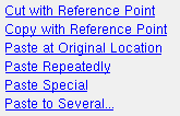
Following is the default context menu (with all items shown) that you get when you right-click in the drawing area in the Drawing Editor . Some options on this context menu are visible only when there is a particular selection or when an item is hovered with your mouse pointer (
).
 |
""""""" E dit Other and Select Other are built-in cascade menus. Template Rules and Tiles " and " Special " are custom cascade menus. For labels , " Edit Other " lets you edit all labels with the same text. Click here and here for examples of the context menu being used in the Drawing Editor . |
 |
The " Special " cascade menu. |
 |
The " Template Rules " cascade menu. |
 |
The " Tiles " cascade menu. |
page 1 | contents | selection | drawing editor | top
Select+ (left button on a 3-button mouse with Shift pressed)
|
|
|
default bindings ( Shift key pressed) |
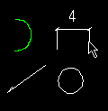
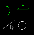
| Hold down Shift and left-click to select more than one item one at a time. | |
|
|
| 1 . Place your mouse pointer ( |
2 . The item turns green (cyan if green already). You can then select more items using Select+ . |
Tips and tricks for Select+:
page 1 | contents | selection | drawing editor | top
Select- ( left button with Ctrl pressed )
|
|
|
default bindings ( Ctrl key pressed) |
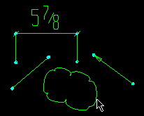
| Select- to deselect an object. | |
|
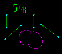 |
| 1 . Hold down the Ctrl key and left-click ( Select- ) an object that is currently selected. | 2 . The object is deselected (no longer green). |
Tips and tricks for Select-:
page 1 | contents | selection | drawing editor | top
Toggle ( left button with Ctrl+Shift pressed )
|
|
|
default bindings ( Ctrl+Shift key pressed) |
| Toggle to deselect an object. | |

|
 |
| 1 . Hold down the Ctrl+Shift keys and left-click ( Toggle ) a selected object. | 2 . The object is deselected (no longer green). |
Tips and tricks for Toggle:
page 1 | contents | selection | drawing editor | top
To select/deselect objects by area :
| Selection Versus Deselection: An area box drawn using Select or Select + can only be used to select items. An area box drawn using Select- can only deselect items that are already selected. An area box drawn using Toggle inverts the selection state of items so that previously selected items are deselected and previously unselected items are selected. |
| Hold down the left mouse button and drag (with or without Shift or Ctrl pressed) to select/deselect multiple items by area. | |
| Selection filters affect what types of objects are selected or deselected by the area box . |

|
| Also see: When " Point selection by area box " is set to ' Directional ', an area box may select or deselect more objects when drawn from right to left. | |
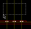
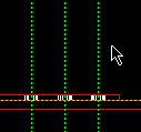
| Draw the area box from right to left to select construction lines or user-named viewports by area. | |
|
|
| 1 . Hold down the left mouse button ( Select ) and drag your mouse pointer ( |
2 . All construction lines within the area box are selected. |
| Note: User and Site Options > General > " Point selection by area box " must be set to ' Directional ' for this to work. Also, the selection filter for ' Construction Lines ' must be selected. User-named viewports can be selected (on the original drawing) with the ' Default ' or ' All ' or ' Viewports ' selection filters. | |
page 1 | contents | selection | drawing editor | top
Dragging objects in Select Items mode :
| Tip: While dragging selected items, you can press the Esc key to cancel. The selected items revert to their original location. |
The mouse pointer shows the directional constraint of dragging:
|
|
1-way mouse pointer | Hold down the left mouse button ( Select ) while over an item. The mouse pointer becomes 2-way or 4-way to show the item has been grabbed. |
|
|
2-way mouse pointer (horizontal, vertical or diagonal) | While still holding down the left mouse button ( Select ), drag the 2-way pointer to stretch or move the object under it in either of two directions. Certain types of objects snap to Drag and Drop Configuration points. |
|
|
4-way mouse pointer | While still holding down the left mouse button ( Select ), drag the 4-way pointer to move or stretch the object under it freely in any direction or in any of four directions. |
To move arcs , circles , clouds , holes , bolts , labels , a member's piecemark , etc:
| Dragging a label (or arc, circle, cloud). | ||
 |

|

|
|
1 . Press the left mouse button ( Select ) to grab
the object. |
2 . Drag the object to a new location. | 3 . Release the mouse button when the object is where you want it. |
Note: You cannot stretch arcs or circles or holes or bolts by dragging them -- they can only be moved. You can stretch clouds and material polygons using Move/Stretch or by dragging their end points .
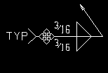
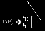
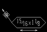
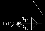
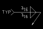
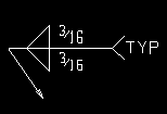
To move a weld or hole symbol or label combo or bolt symbol and stretch or break off its attached pointer:
|
|
Drag the symbol to stretch the attached pointer (or line). |
|

|
Drag the pointer to move it and the symbol as a single object. |

|
|
Hold down the Shift key to break a symbol off the pointer. |
|
|
Dragging a weld symbol to opposite its pointer flips " Symbol rotation " 180 degrees. |
To change a pointer's curvature:
|
|||||
| Hold down the Shift key and drag the middle of the pointer to straighten the pointer or change its " Pointer curve ." |
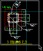
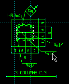
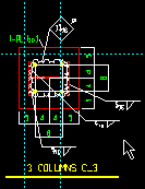
| Drag a group of selected objects to move them. | ||
|
|
|
| 1 . Select the objects. In this example, by area box . | 2 . Grab anywhere on the group then drag the group to a new location. | 3 . Release the mouse button, then click in space to deselect the objects. |
To move/stretch pointers or lines :
| A special case: Lines that are a part of polygons (e.g., material lines) cannot be moved/stretched as described below. They need to be moved/stretched using Move/Stretch . To move a polygon, you need to select the entire polygon. To stretch a polygon, you need to select end points . |
|
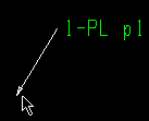
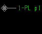
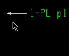
Drag either end of a pointer (or line)
to stretch the object. |
||
|
|
|
| 1 . Press the left mouse button ( Select ) to grab
the end of the pointer. |
2 . Drag the end of the pointer to a new location. | 3 . Release the mouse button when the pointer is stretched the way you want it. |
|
Drag the interior of a pointer (or line)
to move the object. |
||

|

|

|
| 1 . Press the left mouse button ( Select ) to grab
the interior of the pointer. |
2 . Drag the pointer to a new location. | 3 . Release the mouse button when the pointer is where you want it. |
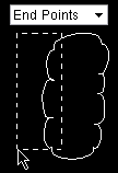
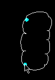
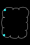
To stretch a cloud or material polygon :
| Warning! Clouds stretched at an angle may be difficult to Shorten . Clouds should approximate rectangles. |
| Drag the end points for one side of a cloud or material polygon to stretch the item. | ||
|
|
|
| 1 . Select the cloud's end points by area box with the selection filter set to ' End Points ' or ' Default '. | 2 . Drag the selected points to a new location. Tip : let the end point change color before you grab it. | 3 . Release the mouse button when the cloud is stretched the way you want it. |
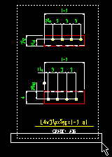
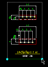
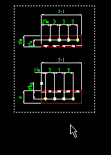
To adjust a viewport by dragging end points :
| Note: If this is done to a sheet item , a custom viewport is created, and the original viewport is not changed. If this is done to the original drawing, the viewport is changed on all sheet items that are linked to that drawing. |
| With the selection filter set to ' Default ' or ' End points ' and " Viewports " on: | ||
|
|
|
| 1 . Draw an area box (or Shift and click) to select two end points . | 2 . Grab one end point and drag it. | 3 . The viewport is now ' Custom '. Undo if you don't like the result. |
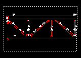
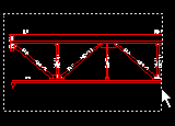
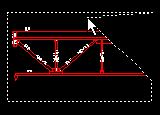
Drag the perimeter of a viewport to give it a new shape:
| Note: If this is done to the sheet item , a custom viewport is created, and the original viewport is not changed. If this is done to the original drawing, the viewport is changed on all sheet items that are linked to that drawing. |
| With the selection filter set to ' Default ' and " Viewports " on: | ||
|
|
|
| 1 . The default (' Extents ') viewport is rectangular, with end points at the four corners. | 2 . Click on the viewport to add a new point. | 3 . Drag the point in any direction to change the shape of the viewport. Undo as needed. |
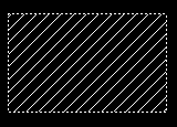
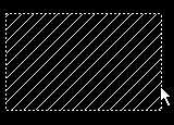
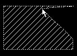
Drag a defined polygon for hatching to give it a new shape:
| Note: This doesn't work with any polygon. It only works when the polygon has been defined using Objects > Hatch > Add Define Polygon . |
| With the selection filter set to '' Default : | ||
|
|
|
| 1 . The defined polygon shape is rectangular. | 2 . Click a polygon side to add a new point. | 3 . Drag the point in any direction to change the shape of the polygon. |
To drag parts of dimensions :
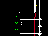
| Drag a dimension line to stretch chain dimensions. | ||
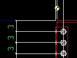
| Note: The leg snaps to Drag and Drop Configuration points within the " Aperture " range of the mouse pointer. Outside the " Aperture " you get a free point. If you grab the dimension label instead of the dimension line or hold down the Ctrl key, the chain moves freely. | ||
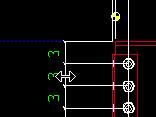
| Press the left mouse button ( Select ) to grab a dimension line in a chain of dimensions and move the entire chain. |
|
|
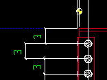
| If you hold down the Shift key before grabbing the dimension line ( Select+ ), you will move only the one dimension line. |
|
|
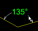
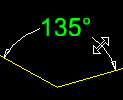
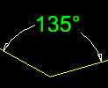
| Dragging an angle dimension line (the line with arrows) | ||
 |
|
|
| 1 . Grab the dimension line of the angle dimension. | 2 . Drag the angle dimension laterally. | 3 . The dimension line is resized. Degrees stay the same. |
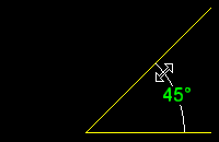
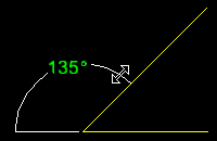
| Dragging an angle dimension line to a different quadrant | |
 |
|
| 1 . Grab the dimension line and drag it to a different quadrant. | 2 . The dimension label is recalculated. . |
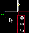
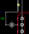
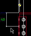
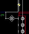
| Drag a dim leg to change the dimension or leg length. | |||
| Note: The leg snaps to Drag and Drop Configuration points within the " Aperture " range of the mouse pointer. Outside the " Aperture " you get a free point. " Freeze label " is not checked in these examples. Also see this note . | |||
|
|
|
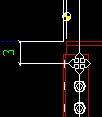
To change the dimension size , press the left mouse button ( Select ) to grab the foot of a dimension leg and drag it parallel with the dimension line. |
|
|

|
To change the leg length , press the left mouse button ( Select ) to grab a dimension leg and drag it perpendicular to the dimension line. |
To move a dimension label or angle dimension label or arc dimension label:
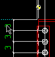
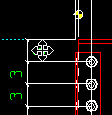
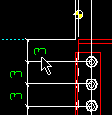
| Hold the Shift key and drag the dim label to move it. | ||
|
|
|
| 1 . Hold down Shift and press the left mouse button ( Select+ ) to grab the dimension label. | 2 . Drag the dimension label freely in any direction. | 3 . Release the mouse button when the dimension label is where you want it. |
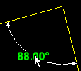
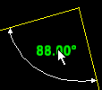
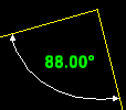
| Same as above, but with an angle dimension label. | ||
 |
|
|
| 1 . Hold down Shift and press the left mouse button ( Select ) to grab the dimension label. | 2 . Drag the dimension label to a new location. | 3 . Release the mouse button when the dimension label is where you want it. |
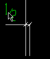
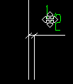
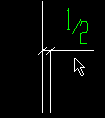
| Drag a dimension label to stretch/create a tail or change its side. | ||
|
 |
|
| 1 . Press the left mouse button ( Select ) to grab
a dimension label. |
2 . Drag the label to stretch the dimension tail or change its side. | 3 . Release the mouse button. |
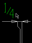
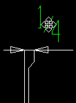
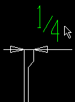
| Drag a dimension label to change the expansion offset side. | ||
|
|
|
| 1 . Press the left mouse button ( Select ) to grab
a dimension label. |
2 . Drag the dimension label to change the expansion offset side. | 3 . Release the mouse button. |
To stretch/move a bevel symbol :
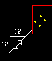
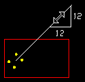
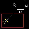
| Drag a bevel symbol to stretch its tail or flip its side. If the bevel symbol has no tail, the bevel symbol can only be moved, not stretched, and you must use its edit window to flip it. | ||
|
|
|
|
1 . Press the left mouse button ( Select ) to grab
the triangle of the bevel symbol along the bevel line. |
2 . Drag the bevel symbol. In this example, the user flips the symbol with respect to the bevel line. | 3 . Release the mouse button. Note that the tail's end point has remained fixed. |
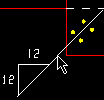
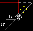
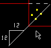
Drag a bevel symbol's tail to move the symbol. On a bevel symbol with a tail, you must grab the tail to move it. If there is no tail, grab anywhere. |
||
|
 |
|
|
1 . Press the left mouse button ( Select ) to grab
the tail of the bevel symbol. |
2 . Drag the bevel symbol in any direction. | 3 . Release the mouse button. |
To move a construction line or construction circle :
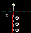
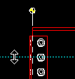
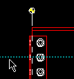
| Drag a construction line to move it. (the construction line snaps to Drag and Drop Configuration points within the " Aperture " range of the mouse pointer) |
||
|
|
|
| 1 . With ' All ' or ' Construction Lines ' the selection filter , press the left mouse button ( Select ) to grab a construction line. | 2 . As you drag the construction line, it snaps to Drag and Drop Configuration points. | 3 . Release the mouse button when the construction line is where you want it. |
|
||
| With ' Construction Circles ' the selection filter , grab the edge of a construction circle . The exact point at the center of the construction circle snaps to Drag and Drop Configuration points within the " Aperture " range as you drag the construction circle across your computer screen. |
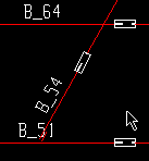
To move a MOI (Member Orientation Indicator):
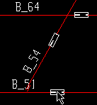
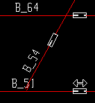
| Drag an MOI to move it. | ||
|
|
|
| 1 . With ' Default ' or ' Members ' the selection filter , press the left mouse button ( Select ) to grab the MOI. | 2 . As you drag the MOI, the 2-way mouse pointer shows the directional constraint. | 3 . Release the mouse button when the MOI is where you want it. |
Move an image by dragging its center:
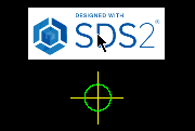
|
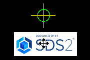
|
| 1 . With ' Default ' or ' All ' the selection filter , press the left mouse button ( Select ) to grab the middle of the image. | 2 . A 4-way pointer shows you can drag the image in any direction. Release the mouse button when the image is where you want it. |
Re-size an image by dragging its border:
|
In this example, " Keep display ratio " is checked ( |
|

|

|
| 1 . With ' Default ' or ' All ' the selection filter , press the left mouse button ( Select ) and grab the edge of the image. | 2 . A 2-way pointer is shown at the edge of the image that you are dragging. Release the mouse button when the image is re-sized the way you want it. |
page 1 | contents | selection | drawing editor | top
