Crane Limits and Appearance
- Step-By-Step
- Tips and Tricks
- Related Tools
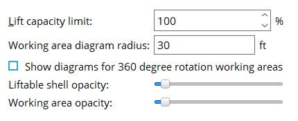
Lift capacity limit: The percentage that is the default Capacity limit for a crane that is newly added using Add Crawler Crane or Add Tower Crane.
Example: You enter 90% as the Lift capacity limit here. You then do an Add Crawler Crane and, on the Crane Placement window, press the Lift Config button. On the Lift Configuration window for the new crawler crane, you find that the Capacity limit is 90%. You can change that Capacity limit if you so choose.
Working area diagram radius: The radius of the working area shown on a crane placement's working area diagram. A working area is a configuration of a truck or crawler crane's lower works that determines its quadrants of operation. A working area diagram shows these quadrants extended to the radius that you choose.
|
||
| A working area diagram radius is measured from the center of a crane placement. |


Note 1: Some working areas consist of a single 360 degree quadrant. Such diagrams are visible only when Show diagram for 360 degree rotation working areas is checked (
).
Note 2: When the project's primary dimension Units are imperial (that is, set to Imperial (ft-in) or Imperial (inches-sixteenths) or etc.), this radius is expressed in feet. When the primary dimension Units are set to Metric, this radius is expressed in meters. In either case, the radius is always expressed as a whole or decimal number.
Note 3: A truck crane's quadrants are defined under Working Areas on the Truck Crane Specification window. A crawler crane's quadrants are defined under Working Areas on the Crawler Crane Specification window. Working Area on the Lift Configuration window lets you define the quadrant of operation that is to be used for a particular lift. Working areas are not configured for tower cranes; consequently, working area diagrams are never shown for their placements.
Show diagram for 360 degree rotation working areas: ![]() or
or ![]() . This applies to truck or crawler crane placements with a single 360 degree quadrant.
. This applies to truck or crawler crane placements with a single 360 degree quadrant.
|
||
| "Show diagram" has no effect on placements of cranes that have two or more quadrants in their working areas. |


If this box is checked (
If the box is not checked (
), no working area diagram is shown for placements of cranes that that have a single 360 degree quadrant.
Liftable shell opacity: Any level from 0 (transparent) to 100 (opaque). The liftable shell is the dome that is displayed when you left-click a crane in your Modeling view.
|
|
|
the slider sets the level |
|
||
| The "dome" around the crane placement represents the reach of the crane's boom. The center cylinder is the no-lift zone around the crane. The alternating dark and light bands are each 10 ft in width. |

Working area opacity: Any level from 0 (transparent) to 100 (opaque). This applies to working area diagrams shown for truck and crawler crane placements.
|
|
|
the slider sets the level |
|
||
| When a working area is opaque, member main and member connection material cannot be seen through it. |


|
|
OK (or the Enter key) closes this screen and applies the settings.
Cancel (or the Esc key) closes this screen without saving any changes.
Reset undoes all changes made to this screen since you first opened it. The screen remains open.
- Red or yellow exclamation point icons
 or
or 
- Settings applied to the Crane Limits and Appearance screen are for your current Fabricator. A different set of settings will apply when you Change Fabricator.

