 Add Tower Crane ( Modeling )
Tool summary :
Also see :
- Tower Crane (window that Add Tower Crane opens)
- Add/Edit Tower Crane Specification (before adding a tower crane)
- Edit Crane (to edit a crane after it has been added)
- Copy Crane (an alternative way to add a new crane)
page 1 | contents | model > crane > | cranes | cranes (index) | tower crane window
 Add Tower Crane (step-by-step instructions) :
You should be in a plan view in Modeling at the elevation you want to add the crane to. Use Edit Tower Crane Specification to confirm that the crane that you want to add is available. If it is not, you should first create a new specification that matches the actual manufacturer's specifications.
1 . Invoke Add Tower Crane using any one (1) of the following methods:
Method 1 : Click the Add Tower Crane icon, which is pictured above. The icon can be taken from the group named ' Model -- Cranes ' and placed on a toolbar (classic) or the ribbon (lightning).
Method 2 : If " Modeling layout style " is ' Classic ', you can use the menu system to choose Model > Cranes > Add Tower Crane .
Method 3, 4 or 5 : Add Tower Crane can also be configured to be invoked using a keyboard shortcut , the context menu , or a mode . Using the default context menu, for example, you can right-click ( Menu ) and choose Add ... .
2 . The Select tower crane specification window opens. On it is a list of tower crane specification files.
Alternative 1 : Select a tower crane specification that exactly matches the actual crane that will be used at the construction site, then press the " Open " button. Go to step 3.
Alternative 2 : If you can't find a crane specification that exactly matches, press the " Cancel " button to end this operation. Use Add/Edit Tower Crane Specification to create a specification that matches the actual crane that will be used.
3 . The Tower Crane window opens.
3a : Give the crane you are adding a " Name " and make other entries as needed. Press the " OK " button to continue.
4 . The Crane Placement window opens.

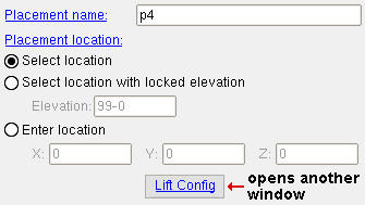
4a : Enter an " Placement name " and choose the method you want to employ to designate the " Placement location ". Press the " OK " button to continue.
Regarding the " Lift Config " button: If you pressed the " Lift Config " button on the Tower Crane window, then the settings that you applied to the version of the Lift Configuration window which appeared at that time are the default settings (the "
AUTO" settings) for the version of the Lift Configuration window that appears when you press " Lift Config " on the Crane Placement window.
5 (if applicable) : If, for " Placement location " in the previous step, you selected " Select location " or " Select location with located elevation ", you will be prompted (by the status line ), to " Locate crane placement ". Skip this step if you selected ' Enter location ' in the previous step.
5a : Optionally select a Locate option (e.g. INCL ), then move your mouse pointer (
) so that the point location target (
) snaps to the point where you want the crane and its crane placement to be centered, then left-click ( Locate ).
Tip: The X, Y, Z display tells you the coordinates of a point.
Note: After the crane has been added, you can Edit the crane placement and change the " Placement location " if you so choose.
6 . The status line prompts, " Choose footing orientation ."
|
|
|
mouse bindings |

|
The model's footing orientation does not affect the Lift Information of any lifts that you later add to the placement. |
6a : Move your mouse pointer (
) so that the point location target (
) snaps to any point along an axis which you want to be parallel with the " Length " of the pad, then left-click ( Locate ).
Note: After the crane has been added, you can Edit the crane placement and " Change footing orientation " if you so choose.
7 . The status line prompts, " Locate furthest laydown point ". The furthest laydown point is used as the pick point when Show Liftable Members evaluates liftability at the pick point. It is the default pick point " Location " for any member lift or load lift (user-defined lift) or multi-lift that you later assign to the crane placement that you are adding along with this crane.
|
|
|
mouse bindings |

|
When a crane placement is selected, the furthest laydown point for that placement is identified with a |
7a : Move your mouse pointer (
) so that the point location target (
) snaps to the point you want, then left-click ( Locate ).
Note: After the crane has been added, you can Edit the crane placement and " Change furthest laydown point " if you so choose.
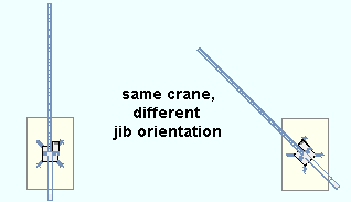
8 . The status line prompts, " Choose jib orientation ". This sets how the jib of the crane will be pictured in the model. It does not affect Lift Information .
|
|
|
mouse bindings |

|
Jib orientation does not affect the Lift Information of any lifts that you later add to the placement -- it is for appearances only. |
8a : Move your mouse pointer (
) so that the point location target (
) snaps to any point along an axis that you want the jib to be oriented with respect to, then left-click ( Locate ).
Note: After the crane has been added, you can Edit the crane and " Change jib orientation " if you so choose.
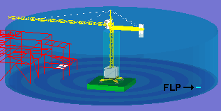
9 . The tower crane and crane placement are now added in the model, centered at the point you located in step 5 or entered in step 4 (if you chose ' Enter location ' for " Placement location ").
Note: A crane can have multiple crane placements . You can move a tower crane to a different placement if you Edit the crane and choose to " Change placement ". Moving a crane to a different placement will not affect Lift Information . It only affects where the crane is shown in the model. Lift Information is calculated based on the position of the crane placement, not on the position of the crane.
page 1 | contents | model > crane > | cranes | cranes (index) | tower crane window | top


