Splice Plate (beam-to-beam) ("  Connection specifications " and more)
On this page :
- Information:
- Connection specifications:
- Locks:
Setup of beam splice plate connections :
- Top of Steel to First Hole ( Schedule of Minimums )
- Schedule of Minimums (bolt diameters/ number of bolt rows)
- Bolt spacing (vertical spacing between rows, per bolt diameter)
- Amount of allowable k infringement (placement)
- Plates (setup window sets default grade by connection type)
- Available bolt sizes (when connection design increments diameters)
- Field clearance (non-autostandard)
Also see :
- Status Display ( Connection type > Splice )
user defined | beam | system
General info about beam splice connections :
user defined | beam | system | top
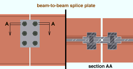
Illustrations of splice plate connections :

user defined | beam | system | top
------ " ![]() Connection specifications " for beam ' Splice plate ' connections ------
Connection specifications " for beam ' Splice plate ' connections ------
|
" |
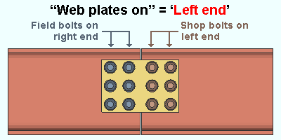
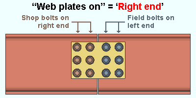
Web plates on: Left end or Right end or Both members .
|
|
In a full-featured SDS2 program . . .
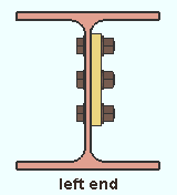
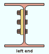
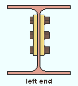
' Left end ' specifies that connection design shop bolt the splice plate(s) to the beam whose left end is being connected by the web splice connection. ' Left end ' is automatically selected for both beams when you select it for one of the beams being spliced. The " Web plate side " option is enabled.
' Right end ' instructs connection design to shop bolt the splice plate(s) to the beam whose right end is being connected by the web splice. The " Web plate side " option is enabled.
' Both members ' designs near- and far-side splice plates (two plates) and disables ( grays out ) the " Web plate side " option. One splice plate ships with the one beam, the other with the other beam, and all bolts on both beams are field bolts.
Web plate side: Near or Far or Both . This applies when -- here in " ![]() Connection specifications " -- " Web plates on " is set to ' Left end ' or ' Right end '.
Connection specifications " -- " Web plates on " is set to ' Left end ' or ' Right end '.
|
|
|
In a full-featured SDS2 program . . .
' Near ' bolts the one web splice plate to the near side of both beams.
' Far ' bolts the one one web splice plate to the far side of both beams.
' Both ' generates splice plates on both sides of the beam. The splice plates shop bolt to the left end of the one beam or the right end of the other beam depending on the choice made to " Web plates on ."
Splice plate grade: Auto or select a material grade .
In a full-featured SDS2 program . . .
'
Auto (checked) ' specifies that connection design enter the " Plate material grade " from Home > Project Settings > Fabricator > Standard Fabricator Connections > Preferred Plate Sizes > the " Splice Plates " section.
'
Auto (not checked) ' lets a user in that full-featured SDS2 program select a steel grade on the list box (
). Choices shown in that list box come from Home > Project Settings > Job > Plate Grades .
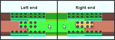
Flange plates on: Left end or Right end . This " ![]() Connection specifications " option applies to beam splice connections when the " Moment type " is set to ' Bolted ' in this beam's "
Connection specifications " option applies to beam splice connections when the " Moment type " is set to ' Bolted ' in this beam's " ![]() Moment " leaf.
Moment " leaf.
|
| This example shows inner flange plates as well as top and bottom moment flange plates. |
In a full-featured SDS2 program . . .
' Left end ' specifies that the flange plates shop bolt to the beam whose left end is being spliced. This choice needs to be made on only one of the beams. The ends of both beams that are being spliced automatically have " Flange plates on " set to ' Left end ' when ' Left end ' is the choice for one of the beams.
' Right end ' specifies that the flange plates shop bolt to the beam whose right end is being spliced. Making this change on one of the beams being spliced automatically applies that same choice to the other beam that is being spliced.
user defined | beam | system | top
Connection design locks for beam splices :
Connection design locks for beam splices may appear, under a leaf with one of the below-listed names, on the Beam Review window, or on a Connection Component window. The locks can also appear on the User Defined Connections window.
| Connection Design Locks (" Input connection type " = ' Splice plate ') |
|
| Leaf Name | Situation |
| Web Plate | These locks become available on the Beam Edit window when ' Splice plate ' is the " Input connection type " for the appropriate end of each of two end-to-end beams. Web splices may be designed with or without top/bottom moment flange plates. |
| Web Fill Plate | These locks are, by default, filled out with values of ' 0 ' if the two beams being spliced have equal web thicknesses. |
| Moment Flange Plate | These locks become available when bolted moment flange plates are specified for a beam splice connection. In other words, when the " Connection material " is ' Plate '. |
user defined | beam | system | top
