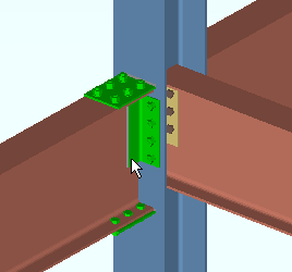
Connection Component window (read-only)
 |
The Connection Component window contains reviewable settings for system connections , which are connections that have been created by connection design in a full-featured SDS2 program. In SDS2 Site Planning, the settings on this window are read-only. |
| Note : The [ Left end ] banner shown above will read [ Right end ] if the component is on the right end of a member. A column's bottom end is its left end. Settings shown on this window exactly match equivalent settings that are shown on the left or right end of the member review window. | |
page 1 | contents | edit | top
To open the Connection Component window :

|
Method 1 : With the ' Default ' or ' Connection Components ' or ' All ' filter selected, double-click a system connection material to open the Connection Component window for that connection. |

|
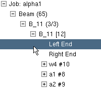
Method 2 : In the Model Tree , with " View By " set to ' Member Piecemark ' or ' Member Number ', double-click a member's ' Left End ' or ' Right End '. The connection component window opens for the system connection on that end of the member. |
page 1 | contents | edit | top
|
|
|
|
" Locked" or "Unlocked " |
||
" Locked " ( ![]() ) or " Unlocked " (
) or " Unlocked " ( ![]() ):
):
indicates that, in a full-featured SDS2 program , all options are disabled (grayed out) here, on the Connection Component window, and also on the member window, thus preventing users from making changes to the end connection. To preserve the connection, users of that program are also prevented from manually editing or cutting or deleting connection materials associated with this connection component. Process and Create Solids will not change the connection.
indicates that a user of a full-featured SDS2 program is allowed to edit the settings on this window.
Status Display: Approval and modeling > Member end locked
page 1 | contents | edit | top
![]() Information ----------------------------------------------------------------------
Information ----------------------------------------------------------------------
If you are editing multiple connection components and the members those components belong to have different connection failed or connection-changed messages, a banner like the following is displayed:
| Multiple failed and/or changed connection messages |
The " Connection design locks set " banner notifies you that at least one setting in the connection is locked (
):
| Connection design locks set. |
|
Search: Connection design locks set
Status Display: Search > Connection design locks set
A red connection failed message like that shown below indicates a connection failure . Along with the message, you will find a ![]() button for context-sensitive help about the message.
button for context-sensitive help about the message.
| Beam web shear capacity failed |
|
Connection failure messages by member type:
|
launches your " Help browser " and gives you context-sensitive help about a connection failed message . If there is no connection failed message, this button will not be shown. A connection failed message may be generated, for example, due to "
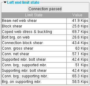
Left/Right End Limit State " analysis having revealed that a connection cannot carry the load that the connection's member is subjected to. The various limit states associated with a connection are tested during connection design .
A green " Connection changed ... " banner indicates that, in order to make the connection work, connection design has deviated from the connection specifications that were entered by the user in a full-featured SDS2 program .
| Conn changed. Possibly: Angle vs Plate |
Search: Connections Changed by System .
Connection: Force and/or Graphical.
![]()
' Force ' indicates a failed connection has been forced to be designed in a full-featured SDS2 program . The Connection Design Calculations report (and Expanded Connection Design Calculations ) will include a warning notifying the reader that the connection has been forced.
' Graphical ' indicates that the connection is graphical and, therefore, will not be changed during connection design in a full-featured SDS2 program . The Connection Design Calculations report (and Expanded Connection Design Calculations ) will include the warning " GRAPHICAL CONNECTION -- STRENGTH CALCULATIONS NOT GENERATED ."
Status Display: Search > Graphical connections
page 1 | contents | edit | top
![]() End Preparations ---------------------------------------------------------------
End Preparations ---------------------------------------------------------------
Top flange operation : ' None ' or ' Cope plain ' or ' Cope field weld #3 (Standard) ' or ' Cope shop weld #3 (Standard) ' or ' Cut flange width ' or ' Cut flange flush ' or ' Clip flange ' or ' Notch Top/Bottom ' or ' Notch near side/far side ' or ' Cope field weld #1 (FEMA) ' or ' Cope shop weld #1 (FEMA) ' or ' Clip web ' or ' Seismic cope field weld ' or ' Seismic cope shop weld '.
page 1 | contents | edit | top
|
Some examples of the connection design lock sections that you might see on the Connection Component window for a beam connection. |
"
Show images " when checked, displays drawings that depict the dimensions that are controlled by connection design locks .
"
NS Clip " and "
FS Clip " and "
Beam Web Doubler " and "
Web Extension Plate " in the above example are leaves for connection design locks.
Links to connection design lock documentation:
More links (by connection type):
page 1 | contents | edit | top
Left/Right End Limit State ----------------------------------------------------

The limit states for a clip angle connection on the left end of a beam. The values shown represent the strength capacity of the connection or of the supported member (this beam) or of the supporting member. In this example, the connection passes.
To close the Connection Component window :


" Edit Member " closes this read-only window and opens the member review window associated with the connection component that you are reviewing.
" OK " (or the Enter key) closes the Connection Component window.