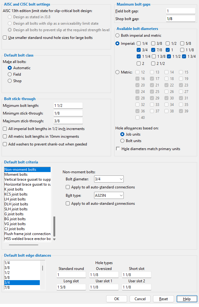
The Bolt Settings window ( Job Settings )
- Job Settings that you can review on this read-only window apply in a full-featured SDS2 program to the design of connections when Auto has been selected for either moment or non-moment bolts. Connection design references the information that this window is populated with to determine which bolt sizes are available to design a connection that stands up to loading conditions.
Also see :
- Bolt Specifications (sets available bolt grades)
- Connection design (settings on this window are applied during)
page 1 | contents | home > project settings > job > bolts, washers, and holes > | classic | top
Method 1 : Home > Project Settings > Job > Bolts, Washers, and Holes > Bolt Settings .
Methods 2, 3 & 4 : In Modeling or the Drawing Editor , choose Settings > Job Settings > Bolt Settings (classic), or use a keyboard shortcut , or click the icon.
page 1 | contents | home > project settings > job > bolts, washers, and holes > | classic | top
------ Default bolt criteria ------
Bolt diameter: The diameter of bolts for fastening non-moment connection materials to structural members.
diameter 
Note 1: The selection shown here influences connection design in a full-featured SDS2 program and also sets which holes will be identified on details when the box for " Show nonstandard hole sizes on detail drawings " is checked.
Note 2: Connection design determines the minimum bolt diameter for the creation of a non-moment, non-auto-standard connection other than a brace gusset plate from the value that is entered here or, if applicable, from the " Bolt Diameter " entered for structural members or from the " Bolt Diameter " entered for single-plate shear connections (it uses whichever value is largest). If the program finds that it needs to use a bolt diameter larger than the minimum so that the connection will withstand the stress of heavy loading, it uses one of the " Available imperial bolt sizes " or " Available metric bolt sizes ."
Note 3: Connection design calculates hole diameter from the input bolt diameter per the selected " Connection design method ." For AISC design codes, this calculation is per AISC Table J3.3 or Table J3.3M ( Thirteenth Edition , p. 16.1-105).
Apply to all auto-standard connections: Not applicable to an SDS2 review station since its state is always not checked (
).
In full-featured SDS2 programs, users can check this option to cause the bolt diameter that user enters to the line above to override non-moment bolt diameters set for individual auto standard connections . After the user closes this window, the state of this check box reverts to not checked.
Bolt type: A325N or A325SC or A325X or etc. This is the default non-moment bolt for fastening non-moment connection materials to structural members. Any bolt type in the User Defined Bolt Specifications may be entered here. On member windows such as the Beam Review window, the " Bolt type " selected here is automatically used in the design of non-moment connections when the " NM bolt type " is set to "
Auto ."
Apply to all auto-standard connections: Not applicable to an SDS2 review station since its state is always not checked (
In full-featured SDS2 programs, users can check this option to cause the bolt type that user enters to the line above to override the non-moment bolt types set for individual auto standard connections . After the user closes this window, the state of this check box reverts to not checked.
Bolt diameter: The default diameter (inches or mm) of the shanks of the bolts to be used for ' Bolted ' moment flange plates and angles, moment flange splice plates, and moment end plates. In other words, this sets the "
Moment " leaf on the Beam Review window.
diameter Bolt type: A325N or A325SC or A325X or etc. The default bolt for moment flange plates and angles, moment flange splice plates, and moment end plates. In other words, this sets the "
In a full-featured SDS2 program, any bolt type that has been entered to the User Defined Bolt Specifications may be entered to this field.
Vertical brace gusset to supporting :
Bolt diameter: The diameter of bolts in both legs of the clip angle that fastens the vertical brace gusset to the supporting member. This applies when " Bolt diameter " is set to "
diameter
Bolt type: A325N or A325SC or A325X or etc. The selection made here is the default bolt type for fastening the clip angle to both the gusset and to the supporting member. This applies when the " Bolt type " is set to "
Horizontal brace gusset to supporting :
Bolt diameter: The diameter of bolts in both legs of the clip angle that fastens the horizontal brace gusset to the supporting member. This applies when " Bolt diameter " is set to "
diameter
Bolt type: A325N or A325SC or A325X or etc. The selection made here is the default bolt type for fastening the clip angle to both the gusset and to the supporting beam. This applies when the " Bolt type " is set to "
| diameter |
|
Bolt diameter: Any diameter from the " Available bolts " list. This diameter applies in a full-featured SDS2 program when, on the Joist Review window, a K joist has been entered as the " Section size " and the box for "
Bolt type: A325N or A325SC or A325X or etc. This bolt type applies in a full-featured SDS2 program when, on the Joist Review window, a K joist has been entered as the " Section size " and the box for "
| diameter |
|
Bolt diameter: Any diameter from the " Available bolts " list. This diameter applies in a full-featured SDS2 program when, on the Joist Review window, a LH or DLH joist has been entered as the " Section size " and the box for "
Bolt type: A325N or A325SC or A325X or etc. This bolt type applies in a full-featured SDS2 program when, on the Joist Review window, a LH or DLH joist has been entered as the " Section size " and "
| diameter |
|
Bolt diameter: Any diameter from the " Available bolts " list. This diameter applies in a full-featured SDS2 program when, on the Joist Review window, a joist girder has been entered as the " Section size " and "
Bolt type: A325N or A325SC or A325X or etc. This bolt type applies in a full-featured SDS2 program when, on the Joist Review window, a joist girder has been entered as the " Section size " and "
Flush framed joist connections:
Bolt diameter: The diameter (inches or mm) of bolts to be used when a joist " Input connection type " is ' Flush framed shear ' or ' Flush framed clip angle ' and when the box for "
diameter 
Example: If you enter, on this window, one bolt diameter for " K joist bolts " and a different bolt diameter for " Flush framed joist connections ," the actual auto bolt diameter that is applied by connection design will depend on the connection type. If the end connection is a bearing connection or seated connection, the auto bolt diameter will be the bolt diameter for " K joist bolts ." If the end connection is a flush framed connection, the auto bolt diameter will be the choice made here, under " Flush framed joist connections ."
Bolt type: A325N or A325SC or A325X or etc. The default type to be applied when a joist " Input connection type " is ' Flush framed shear ' or ' Flush framed clip ' and the box for "
HSS welded brace erector bolts:
Bolt diameter: The diameter (inches or mm) of erection bolts that connection design will create when an HSS vertical brace " Pipe/tube end-fitting " or HSS horizontal brace " Pipe/tube end fitting " is set to ' Welded ' and the " NM bolt diameter " (vertical brace) or " NM bolt diameter " (horizontal brace) is set to "
| diameter |
|
Bolt type: A307 or etc. The choice made here is applied, by connection design, when an HSS vertical brace " Pipe/tube end-fitting " or HSS horizontal brace " Pipe/tube end fitting " is set to ' Welded ' and the " NM bolt type " (vertical brace) or " NM bolt type " (horizontal brace) is set to "
page 1 | contents | home > project settings > job > bolts, washers, and holes > | classic | top
------ Default bolt class ------
Make all bolts: Automatic or Field or Shop .
If ' Automatic ' is selected, then connection design in a full-featured SDS2 program will determine the class of bolts based on the following criteria: If the bolt fastens together materials that are submaterials of the same member, that bolt will be a shop bolt. If the bolt fastens together materials that are submaterials of different members, then that bolt will be a field bolt.
If ' Field ' is selected, then connection design will assign ' Field ' as the " Bolt class " to all bolts that fasten to that member.
If ' Shop ' is selected, connection design will assign ' Shop ' as the " Bolt class " to all bolts that fasten to that member.
page 1 | contents | home > project settings > job > bolts, washers, and holes > | classic | top
------ Maximum bolt gaps ------
Field bolt gap: The maximum gap (in the primary dimension " Units " or in other units ) allowed between materials with matching holes that are bolted together with field bolts when holes are matched in a full-featured SDS2 program .
Shop bolt gap: The maximum gap (in the primary dimension " Units " or in other units ) allowed between materials with matching holes that are bolted together with shop bolts when holes are matched in a full-featured SDS2 program .
page 1 | contents | home > project settings > job > bolts, washers, and holes > | classic | top
------ Bolt stick-through ------
Minimum bolt length: The minimum length (in the primary dimension " Units " or in other units ) of bolt to be used in this Job. Head thickness is not included in the calculation of bolt length because head thickness may vary among bolt manufacturers.
| length |
|
Effect on a full-featured SDS2 program: Connection design in a full-featured SDS2 program will not generate bolts that are shorter than the length shown here. This can prevent bolts that are too short from being used in the current Job.
Minimum stick-through: The minimum distance (in the primary dimension " Units " or in other units ) a bolt in this Job will stick through the nut after it has been inserted through the holes in the materials.
s = stick through
![]()
Maximum stick-through: The maximum distance (in the primary dimension " Units " or in other units ) a bolt in this Job will stick through the nut after it has been inserted through the holes in the materials.
s = stick through
![]()
Imperial bolts in 1/2 inch increments: ![]() or
or ![]() .
.
If this box is checked (
If the box is not checked (
Metric bolt lengths in 10 mm increments: ![]() or
or ![]() .
.
If this box is checked (
If the box is not checked (
Add washers to prevent shank-out: ![]() or
or ![]() . Thread length on bolts is set for imperial A325 and A490 bolt sizes per AISC Table C-2.1 ( Thirteenth Edition , p. 16.2-10).
. Thread length on bolts is set for imperial A325 and A490 bolt sizes per AISC Table C-2.1 ( Thirteenth Edition , p. 16.2-10).
If this box is checked (
If the box is not checked (
page 1 | contents | home > project settings > job > bolts, washers, and holes > | classic | top
------ Available bolt diameters ------
Both imperial & metric or Imperial or Metric : The type of bolts which will be used when connection design determines that bolt diameters need to be incremented upward in order to design connections that stand up to the load. The selection shown here also sets which bolt diameters are selectable in the combo boxes ( ![]() ) for " Bolt Diameter " fields.
) for " Bolt Diameter " fields.
' Both ... ' lets the user in a full-featured SDS2 program select both " Available imperial bolt sizes " and " Available metric bolt sizes " in the same Job.
' Imperial ' instructs connection design to use only " Available imperial bolt sizes " when it increments connection bolt sizes to meet loading conditions. This is commonly the selection when ' Imperial ' primary dimensioning " Units " are used.
' Metric ' instructs connection design to use only " Available metric bolt sizes " when it increments connection bolt sizes to meet loading conditions. This is commonly the selection when ' Metric ' primary dimensioning " Units " are used.
Imperial bolts: None or 1/4 and/or 3/8 and/or 1/2 and/or 5/8 and/or 3/4 and/or 7/8 and/or 1 and/or 1 1/8 and/or 1 1/4 and/or 1 3/8 and/or 1 1/2 and/or 1 3/4 and/or 2 and/or 2 1/2 . This option is only valid if ' Imperial ' or ' Both ' is selected above.
When a bolt size is checked (
) for " Bolt Diameter " in Modeling .
Metric bolts: None or selected diameters from 12 mm to 40 mm . This option is only valid if ' Metric ' or ' Both ' is selected above.
When a bolt size is checked (
Hole allowances based on: Job units or Bolt units . In a full-featured SDS2 program, this controls the increment that is used for sizing holes based on a bolt's diameter. The imperial increment is 1/16 inch. The metric increment is 2 mm. See Table J3.3 and Table J3.3M, AISC Fourteenth Edition , pp 16.1-120 and 16.1-121.
|
In a full-featured SDS2 program . . .
' Job units ' results in the 1/16 inch increment being used for all bolts (imperial or metric) when the primary dimension " Units " is ' Imperial'. When the units is ' Metric ', the increment of 2 mm is used for all bolts. Metric bolts that are used in a Job where the primary dimension units is ' Imperial ' will always have their holes sized less than than the 2 mm increment for metric since 1/16 inch is equal to 1.5875 mm.
' Bolt units ' results in the 1/16 inch or 2 mm increment being used based on whether the bolt is an imperial bolt or a metric bolt. If the bolts are imperial bolts, the 1/16 inch increment is used. If the bolts are metric bolts, the 2 mm increment is used. Be aware that when the primary dimension " Units " is ' Metric ', conversion to mm and rounding can cause the hole size for certain imperial bolt sizes to be 1 mm smaller than you might expect given the 2 mm metric increment.
Hole diameters match primary units: ![]() or
or ![]() . This affects the hole diameters that connection design generates in a full-featured SDS2 program for bolts that have diameters in units other than the primary dimension " Units ."
. This affects the hole diameters that connection design generates in a full-featured SDS2 program for bolts that have diameters in units other than the primary dimension " Units ."
| " Units " = ' Metric (mm) ' | |||||
|
|
||||
If this box is checked (
If the box is not checked (
page 1 | contents | home > project settings > job > bolts, washers, and holes > | classic | top
------ AISC and CISC bolt settings------
AISC 13th edition limit state for slip-critical bolt design: This applies when ' ASD13 ' or ' LRFD13 ' is the " Connection design method " and the " Connection Method " assigned to a bolt under the " AISC 13th " tab in the Bolt Specifications is ' Slip Critical '. Refer to the AISC 13th Edition , Section J3.8. Connection design uses equation J3-4 on pg 16.1-109 for slip-critical bolt design.
' Design as stated in J3.8 ' instructs connection design to design slip-critical bolts for serviceability when a bolt fastens through a standard round hole or through a slot that is transverse to the load, but to design for strength on a bolt through an oversized hole or a slot parallel to the load.
' Design all bolts with slip as a serviceability limit state ' instructs connection design to design all slip-critical bolts for serviceability.
' Design all bolts to prevent slip at the required strength level ' instructs connection design to design all slip-critical bolts for strength.
Use smaller standard round hole sizes for lage bolts:
![]() or
or ![]() . This applies when ' ASD15 ' or ' LRFD15 ' is the " Connection design method " ; the bolt diameter ( d ) is 1 inch or greater; and the " Hole type " is set to ' Standard round ', ' Short slot ',
. This applies when ' ASD15 ' or ' LRFD15 ' is the " Connection design method " ; the bolt diameter ( d ) is 1 inch or greater; and the " Hole type " is set to ' Standard round ', ' Short slot ',
' Long slot ', or ' Erection pin hole '. The AISC 15th edition increased the standard hole diameter for large bolts (1 inch diameter and greater) from d +1/16 inch to d +1/8 inch (ref. Table J3.3). This setting allows you to use an AISC 15th edition " Connection design method " with d +1/16 inch standard hole diameter for large bolts. This setting is disabled when " Available bolt diameters " is set to ' Metric ' because the metric standard hole diameters did not change in the AISC 15th edition.
If this box is checked (
), the standard hole diameter for large bolts follows the AISC 14th edition at d +1/16 inch instead of the AISC 15th edition at d +1/8 inch.
If the box is not checked (
page 1 | contents | home > project settings > job > bolts, washers, and holes > | classic | top
------ Default bolt edge distances ------
Bolt diameter: 1/4 or 3/8 or 1/2 or 10 or 11 or 12 or any other selected bolt diameter. When you select a bolt diameter, you get entry fields for setting the minimum edge distance per hole type.
|
| " User slot #1 " and " User slot #2 " are slots that are defined by users (or by default) in Project Settings . |
page 1 | contents | home > project settings > job > bolts, washers, and holes > | classic | top