"  Stiffener Plate " connection design locks
| Beam stiffeners above or below a column with a base/cap plate to a beam are designed per " |
|
|||
| " ( the column must frame to a beam )  |
|
||
Connection Guide: click here for related screen shots.
User Defined Connections: Settings that are locked (
) in a user defined connection file will automatically be locked on a member edit window for which that file is the " Input connection type ." You can, if you so choose, manually lock additional settings on the member edit window, and your changes will be retained, through multiple processes, so long as you do not change to a different connection then switch back to the original user defined connection.
Column Edit: To change a setting, first set it to locked (
). Related settings that are unlocked (
) may be updated, and the "
Left/Right end limit state " calculations will be updated. Settings that are locked (
) will not be changed by connection design , even if doing so might prevent a connection failure.
Connection design locks :
| Locks not dimensioned or called out on the drawing are marked ( not depicted ). |
![]() Stiffener Plate
Stiffener Plate
NS & FS plates, top & bottom
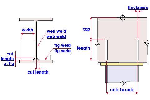
Plate length ( length ): The length of any one of the stiffener plate's vertical edges. See the example . Assuming that the setup option " Align transverse stiffeners for base/cap plate connection with " is set to ' Column ', this distance is measured parallel with the column's work line.
Plate width ( width ): The length of the horizontal edge of the stiffener plate. See the example . Assuming that the setup option " Align transverse stiffeners for base/cap plate connection with " is set to ' Beam ', this distance is measured perpendicular to the beam's depth and parallel with the beam's work line. " Width rounding precision " at Home > Project Settings > Job > Design > Plate Design Settings gives you control over the " Plate width " that is calculated when this option is unlocked (
).
Plate thickness ( thickness ): The " Material thickness " of the stiffener plate. See the example .
Corner clip/cope length ( cut length ): The distance (parallel with the plate width ) between the beginning and the end of the clip or cope cut. See the example .
Corner clip/cope length at flange ( cut length at flg ): The distance (parallel with the plate length ) between the beginning and the end of the clip or cope cut. See the example .
Plate to web weld ( web weld ): The weld size for shop welding the stiffener plate to the web of the supported beam. See the example .
Plate to flange weld ( flg weld ): The weld size for shop welding the stiffener plate to the flange of the supported beam. See the example .
Top location ( top ): The positive (+) or negative (-) distance from the work point of the column to the top edge of the stiffener plate. See the example . ' 0 ' aligns the top edge of the stiffener horizontally with the work point. A positive (+) distance places the top edge of the stiffener that distance above the work point of the column. A negative (-) distance places the top edge of the stiffener that distance below the work point.
Center-to-center distance ( cntr to cntr ): The horizontal distance (center to center) between two stiffeners on the same side (near side or far side) of the beam web. See the example .
Pairs ( not depicted ): 0, 1 or 2. The number of pairs of beam stiffeners. In the above example , the " Pairs of beam stiffeners " is ' 2 '. ' 0 ' removes the beam stiffeners when you next Process and Create Solids . ' 1 ' instructs connection design to create a single pair of beam stiffeners (one on the near side of the beam web, the other on the far side of the beam web). Each stiffener is centered with respect to the work line of the column. ' 2 ' instructs connection design to create two pairs of beam stiffeners (two on the near side of the beam web, two on the far side of the beam web).


