User Base/Cap Plate ("  Connection specifications " and more)
Also see :
- Base/Cap Plate Schedule ( Home > Project Settings > Job for user base/cap plates)
- Setup of user base/cap plates (index)
- Change base/cap plate weld pattern ( Change Options )
- Connection guide (examples of user base/cap plates)
- User defined user base/cap plates (settings)
- Auto standard user base/cap plates
- Status Display ( Connection type > Column base or cap plate )
Design restrictions for user base/cap plates :
------"  Connection specifications " for ' User base/cap plate ' connections ------
| A column's " |
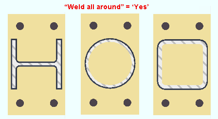
Weld all around: Automatic or No or Yes .
|
Wide flange and HSS round and HSS rectangular columns are shown in this example. HSS round columns are always welded all around, even if you set " Weld all around " to ' No ' and, for example, set " Flange welds " to ' One side '. |

|
Weld symbol "weld all around." |
' Automatic ' welds the column to the user base/cap plate per choices made to " Weld all around " and " Type " (fillet or square groove) and " Size " on the Base/Cap Plate Schedule screen for the relevant plate schedule number. For example, on a column whose user base/cap plate " Plate schedule number " is set to ' 3 ', the " Weld all around " and " Type " and " Size " settings are those settings that are set for line 3 on the Base/Cap Plate Schedule . The " Type " specified in the Base/Cap Plate Schedule can be ' Fillet ' or ' Square groove '.
' No ' prevents a column other than an HSS round or pipe column from being welded all around to the column plate.
' Yes ' welds all around the column to the column plate. The weld will be a fillet type weld. The weld size will be greater than or equal to the " Minimum for job " and less than or equal to the " Maximum for non-strength connections ," which are set at Home > Project Settings > Job > Weld Design Settings .
Connection design locks: "
Column Plate Welds " (
)
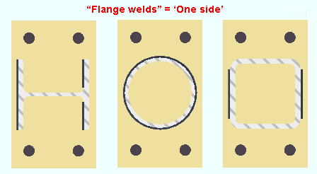
Flange welds: Automatic or None or One side or Both sides .
|
Notice that the HSS round column (middle) behaves as if it had been set to weld all around.. |
|
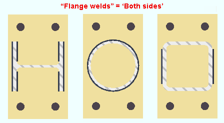
The wide flange column (left) gets one result when ' One side ' is selected, a different result when ' Both sides ' are selected. For the HSS round column (middle) and HSS rectangular column (right), selecting ' One side ' or ' Both sides ' results in the same pattern. |
' Automatic ' welds the column to the user base/cap plate based on choices made to " Flange welds " and " Type " (fillet or square groove or bevel groove) and " Size " on the Base/Cap Plate Schedule screen for the relevant plate schedule number. If the " Type " is ' Bevel groove ', then the specified flange preps will be generated.
' None ' prevents flange welds from being generated.
' One side ' results is a total of three welds on a wide flange column, two on the inner flange faces of one flange, the third on an outer flange face of the other flange. For an HSS rectangular column, only the outer faces of the column's "flanges" are welded to the column plate. The weld will be a fillet weld.
' Both sides ' gives results that are different than ' One side ' only if the column is a flanged shape such as wide flange. For a wide flange column, ' Both sides ' results in the inner faces and outer faces of both flanges being welded to the column plate. The weld will be a fillet weld.
For both ' One side ' and ' Both sides ', the weld will be a fillet type weld. The weld size will be greater than or equal to the " Minimum for job " and less than or equal to the " Maximum for non-strength connections ," which are set at Home > Project Settings > Job > Weld Design Settings .
Connection design locks: "
Column Plate Welds " (
)
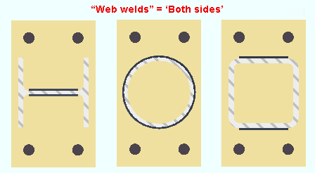
Web welds: Automatic or None or Both sides .
|
The wide flange column (left) and HSS rectangular column (right) get similar weld patterns. The HSS round column (middle) gets a pattern that is similar to the " Weld all around " pattern. |
' Automatic ' welds the column to the user base/cap plate per choices made to " Web welds " and " Type " (fillet or square groove) and " Size " on the Base/Cap Plate Weld screen for the relevant plate schedule number. The weld may be a square groove or fillet weld.
' None ' prevents web welds from being generated.
' Both sides ' gives different results depending on the column material type. See the illustration shown above. The weld will be a fillet type weld. The weld size will be greater than or equal to the " Minimum for job " and less than or equal to the " Maximum for non-strength connections ," which are set at Home > Project Settings > Job > Weld Design Settings . The weld will be a fillet weld.
Connection design locks: "
Column Plate Welds " (
)
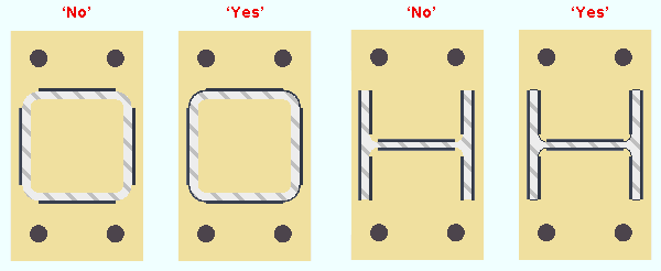
Seal welds: Automatic or No or Yes .
|

|
Seal weld symbol |
' Automatic ' welds the column to the user base/cap plate per choices made to " Seal welds " and " Size " on the Base/Cap Plate Schedule screen for the relevant plate schedule number.
' No ' prevents seal welds from being generated.
' Yes ' adds seal weld to thickness edges and fillets of a wide flange column. For an HSS column, ' Yes ' adds seal weld to HSS corners. " Seal weld size " at Home > Project Settings > Job > Weld Design Settings sets the weld size for the seal welds.
Connection design locks: "
Column Plate Welds " (
)
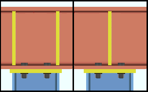
Use transverse beam stiffener: Automatic or As needed or Always or Never . This " ![]() Connection specifications " option applies when a user base/cap plate connects to a beam flange.
Connection specifications " option applies when a user base/cap plate connects to a beam flange.
|
|
' Automatic ' specifies that connection design apply a setup choice ( Home > Project Settings > Job > Design > Design Settings > " Design transverse stiffeners for base/cap plate connection ").
' As needed ' instructs connection design to create one pair of full-depth transverse beam stiffeners (one on the beam's near side, one far side), when the " Load is large enough that the supporting wide flange beam's web capacity is exceeded and stiffeners are required." Two pairs of stiffeners are created when the " Load " is sufficiently large. The two pairs of stiffeners align with the flanges of the column. A single pair of stiffeners is centered with respect to the column work line.
' Always ' instructs connection design to create at least one pair of full-depth transverse beam stiffeners (one on the beam's near side, one far side), regardless of the " Load ." Two pairs of stiffeners are created when the " Load " is sufficiently large. The two pairs of stiffeners align with the flanges of the column. A single pair of stiffeners is centered with respect to the column work line.
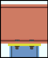
' Never ' instructs connection design to not create full-depth transverse beam stiffeners, even if they are required by connection design. A red banner will appear in "
Information " that reads "Beam web design checks removed by user". This message will also appear in the column's design calculation.
Advanced Selection: UseTransverseBeamStiffener
Parametric module: UseTransverseBeamStiffener
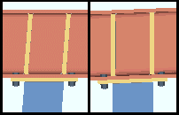
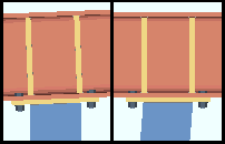
Align stiffeners with: Automatic or Column or Beam . This " ![]() Connection specifications " option applies when the user base/cap plate bolts to the flange of a beam.
Connection specifications " option applies when the user base/cap plate bolts to the flange of a beam.
|
|
' Automatic ' specifies that connection design apply a setup choice ( Home > Project Settings > Job > Design > Plate Design Settings > " Align transverse stiffeners for base/cap plate connection with ").
' Column ' instructs connection design to create transverse beam stiffeners that are parallel with the work line (stick form work line) of the column.
' Beam ' configures connection design to create transverse beam stiffeners that are perpendicular to the workline of the beam. The stiffeners are normal to the beam, regardless of the slope of the beam or column.
Use extended stiffeners: Automatic or Yes or No . This " ![]() Connection specifications " option can apply when a column's user base plate frames to the top flange of a beam. It may also apply when a user cap plate frames to the bottom flange of a beam.
Connection specifications " option can apply when a column's user base plate frames to the top flange of a beam. It may also apply when a user cap plate frames to the bottom flange of a beam.
|
|
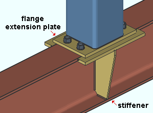
A connection similar to this one may be designed when ' Yes ' or ' Automatic ' is selected for " Use extended stiffeners ." The flange extension plates extend the effective flange width of the beam. NS and FS beam stiffeners are tapered to fit to the flange extension plates. The flange extensions are designed for erection purposes, not as structural supports. |
' Automatic ' specifies that connection design look at the Home > Project Settings > Fabricator > Standard Fabricator Connections > Extended Flange Plate Settings > " Plate overhang tolerance " to determine whether or not to design a connection. If the setup value is less than or equal to the actual base/cap plate overhang in the model, then a connection will be designed. If the setup value is greater than the overhang, a connection is not designed.
' Yes ' instructs connection design to attempt to design flange extension plates and stiffeners. If it is determined that such a connection should not be designed, for example, because of interference with another member, connection design locks are populated with null values (e.g., distances of ' 0 ') in leaves named "
Bottom extension plate " or "
Top extension plate " and "
Stiffener Plate ."
' No ' results in no flange extension plates and beam stiffeners.
Note 1: Tapered stiffeners (as opposed to rectangular stiffeners) can be designed only when the option to " Clip beam stiffener " is on (checked) in Extended Flange Plate Settings .
Note 2: If stiffeners are not needed, setting " Use transverse beam stiffener " to ' No ' may cause them not to be designed.
Setup: Fabricator Setup > Standard Fabricator Connections > Extended Flange Plate Settings .
Connection design locks: "
Bottom extension plate " or "
Top extension plate " and "
Stiffener Plate "
Connection Guide: Beam flange extension plates with tapered stiffeners
Connection design locks for user base/cap plates :
Connection design locks for user base/cap plates may appear, under a leaf with one of the below-listed names, on the Column Edit window, or on a Connection Component window. The locks can also appear on the User Defined Connections window.
| Connection Design Locks
(" Input connection type " = ' User base/cap plate ') |
|
| Leaf Name | Situation |
| Column Plate | Locks under this leaf apply to the bottom end of a column over a supporting beam or joist. Or they apply to the top of a column under a beam or joist. |
| Column Plate | Column does not frame to a beam or joist. |
| Stiffener Plate | Base/cap plate under/over a beam. Fields are zero if beam stiffeners are not needed. |
| Column Plate Welds
( |
You can turn on/off welds for each face of a column that can potentially be welded to the base/cap plate. |
| Left/Right/Top/Bottom Base Plate Extension
( |
Let you add or adjust extensions to a user base cap plate. Making changes to these locks does not affect the Base/Cap Plate Schedule . |
| Top / Bottom Extension Plate (to a beam) | Connection design locks in this leaf let you add or adjust flange extension plates to a beam. |
