"  Column Plate " connection design locks
| An auto base/cap plate to a beam or joist is designed per " |
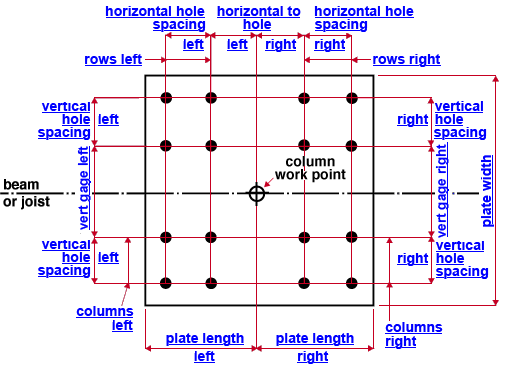
- In the general case (top example), the column work point divides the auto base/cap plate into left and right sections .
- The left and right sections DO NOT have to be mirror images of one another.
- A special case (second example) is for a column whose flanges are perpendicular to the work line of the beam.
- The plate in the second example is divide into left within flange and right within flange and right outside flange and right outside flange sections.
- The left edge of the base/cap plate is the edge nearest to the left end of the beam or joist.
|
|||
|
" |
|
||
|
|||
|
" ( a special case ) 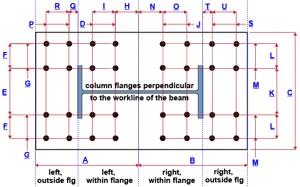 |
|
||
Connection Guide: Click here , here , and here for related screen shots.
User Defined Connections: Settings that are locked (
) in a user defined connection file will automatically be locked on a member edit window for which that file is the " Input connection type ." You can, if you so choose, manually lock additional settings on the member edit window, and your changes will be retained, through multiple processes, so long as you do not change to a different connection then switch back to the original user defined connection.
Column Edit: To change a setting, first set it to locked (
) may be updated, and the "
Connection design locks :
| Note: Locks that are not shown on the drawings are marked ( not depicted ). |
![]() Column Plate
Column Plate
Plate dimensions (auto base/cap plate to a beam or joist)
Length left ( plate length left ) ( A ): So long as this does not say "column only," this is the distance (measured parallel with the work line of the beam or joist) from the work point of the column to the left edge of the auto base/cap plate. The left edge of the plate is the edge that is closest to the left end of the beam (or joist). See the examples . If " Length left " is unlocked (
End connection failure message: " Connection geometry fails due to locked plate/angle length "
If this says " Length left - column only ," the auto base/cap plate is connected to by a vertical brace. For an example, see the " Cap Plate " connection design lock documentation for vertical braces. The distance reported here is, for that situation, the left length of that portion of the auto base/cap plate that is generated by the column. Additional length may be added to the left and/or right of the auto base/cap plate by the vertical brace. This additional length is controlled by the "
Length right ( plate length right ) ( B ): So long as this does not say "column only," this is the distance (measured parallel with the work line of the beam or joist) from the work point of the column to the right edge of the auto base/cap plate. The right edge of the plate is the edge that is nearest to the right end of the beam or joist. See the examples . If " Length right " is unlocked (
End connection failure message: " Connection geometry fails due to locked plate/angle length "
If this says " Length right - column only ," the auto base/cap plate is connected to a vertical brace. For an example, see the "
Plate width ( C ): The width of either one of the edges of the base/cap plate that are perpendicular to the beam (or joist) work line (see example ). If " Plate width " is unlocked (
End connection failure message: " Connection geometry fails due to locked plate/angle width ."
Plate thickness ( not depicted ): The " Material thickness " of the base/cap plate.
All bolts
Hole type ( not depicted ): Standard round or Short slot or Oversized or Long slot or User slot #1 or User slot #2 . The hole type selected here, together with the " Bolt diameter " entered below, set the diameter of holes through the base/cap plate.

Bolt diameter ( not depicted ): You can either type in any diameter (inches or mm), or you can select a bolt diameter from the combo box (
). The diameters that are listed in the combo box come from Home > Project Settings > Job > Bolt Settings > the " Available bolt diameters " list. The bolt diameter entered here (together with the " Hole type ") set the diameter of holes the bolts go into
Left bolts (this reads "Left bolts, within flange" for wide flange)
Rows ( rows left ) ( D ): The number of rows of bolts on the left section (or left, within flange section) of the auto base/cap plate. Bolt row spacing runs parallel with the work line of the beam or joist. For the base plates represented in the examples shown above, the number of bolt " Rows " (left or left, within flange) is ' 2 '. If the plate " Length left " is unlocked (
Vertical gage ( vert gage left ) ( E ): The distance between the two inside columns of bolts (center to center) on the left section (or left within and outside flange sections) of the auto base/cap plate. Bolt column spacing runs perpendicular to the work line of the beam. See the examples . If the " Plate width " is unlocked (
Vertical hole spacing ( vertical hole spacing left ) ( F ): The distance (perpendicular with the work line of the beam or joist) between columns of bolts (center to center) on the left section (or left within and outside flange sections) of the auto base/cap plate. See the examples . If " Plate width " is unlocked (
Columns ( columns left ) ( G ): Half of the total number of columns of bolts on the left section (or the left, within and without flange sections) of the auto base/cap plate. Bolt column spacing runs perpendicular to the work line of the beam. See the examples . For the auto base/cap plate represented in those examples, the number of bolt " Columns " (left) is ' 2 '. If " Plate width " is unlocked (
Horizontal to hole ( horizontal to hole left ) ( H ): The distance (parallel with the work line of the beam or joist) from the work point of the column to the nearest row of bolts. See the examples . Left is toward the left end of the beam (or joist). Changing the " Horizontal to hole " (left or left, inside flange) moves the holes on the plate but does not change the dimensions of the plate.
Horizontal hole spacing ( horizontal hole spacing left ) ( I ): The distance (parallel with the work line of the beam or joist) between rows of bolts (center to center) on the left section (or left, within flange section) of the auto base/cap plate. See the examples . If the plate " Length left " is unlocked (
Right bolts (this reads "Right bolts, within flange" for wide flange)
Rows ( rows right ) ( J ): The number of rows of bolts on the right section (or right, within flange section) of the auto base/cap plate. Bolt row spacing runs parallel with the work line of the beam or joist. See the examples . For the auto base/cap plates represented in those examples, the number of " Rows " (right or right, within flange) is ' 2 '. If " Length right " is unlocked (
Vertical gage ( vertical gage right ) ( K ): The distance between the two inside columns of bolts (center to center) on the right section (or right, within and outside flange sections) of the auto base/cap plate. Bolt column spacing runs perpendicular to the work line of the beam. See the examples . If " Plate width " is unlocked (
Vertical hole spacing ( vertical hole spacing right ) ( L ): The distance (perpendicular with the work line of the beam or joist) between rows of bolts (center to center) on the right section (or right, within and outside flange sections) of the auto base/cap plate. See the examples . If " Plate width " is unlocked (
Columns ( columns right ) ( M ): Half of the total number of columns of bolts on the right section (or right, within and outside flange sections) of the auto base/cap plate. Bolt column spacing runs perpendicular to the work line of the beam. See the examples . For the base plate represented in those examples, the number of bolt " Columns " (right) is ' 2 '. If " Plate width " is unlocked (
Horizontal to hole ( horizontal to hole right ) ( N ): The distance (parallel with the work line of the beam or joist) from the work point of the column to the nearest row of bolts. See the examples . Changing the " Horizontal to hole " (right) moves the holes on the plate but does not change the plate's dimensions.
Horizontal hole spacing ( horizontal hole spacing right ) ( O ): The distance parallel with the work line of the beam or joist between rows of bolts (center to center) on the right section (or right, within flange section) of the auto base/cap plate. See the examples . If " Length right " is unlocked (
|
The connection design locks in this section apply to a wide flange, S shape or welded plate wide flange column whose flanges are perpendicular to the work line of the beam. See the "special case" example (and " |
Rows ( P ): The number of rows of bolts on the left, outside flange section of the auto base/cap plate. See the warning .
Horizontal to hole ( Q ): The distance (parallel with the work line of the beam) from the left flange of the column to the nearest row of bolts in the left, outside flange section of the auto base/cap plate. See the warning .
Horizontal hole spacing ( R ): The distance parallel with the work line of the beam between rows of bolts (center to center) on the left, outside flange section of the auto base/cap plate. See the warning .
|
The connection design locks in this section apply to a wide flange, S shape or welded plate wide flange column whose flanges are perpendicular to the work line of the beam. See the "special case" example . Warning : If a vertical brace gusset plate has been welded (by connection design ) to the right portion of the auto base/cap plate, the right, outside flange bolt group should be controlled with the " |
Rows ( S ): The number of rows of bolts on the right, outside flange section of the auto base/cap plate. See the warning .
Horizontal to hole ( T ): The distance (parallel with the work line of the beam) from the right flange of the column to the nearest row of bolts in the right, outside flange section of the auto base/cap plate. See the warning .
Horizontal hole spacing ( U ): The distance parallel with the work line of the beam between rows of bolts (center to center) on the right, outside flange section of the auto base/cap plate. See the warning .
Welds
Size (to flange) ( not depicted ): The weld size for shop welding the base/cap plate to the column flange. When " Weld pattern " is set to ' All around ', this setting controls that weld size. If you don't want this weld, set " Weld size flange " to ' 0 '.
Size (to web) ( not depicted ): The weld size for shop welding the base/cap plate to the column web. If you don't want this weld, set " Weld size web " to ' 0 '.

