Connection Guide : Column Connections
| Disclaimer: This guide is not comprehensive. It shows only a few of the many cap plates, base plates and column splices that connection design can create. |
| Splices | ||
| Same column section sizes | Different column section sizes | Channel bolted to web |
| Web plates & flange splices | Field welded, HSS rectangular columns | Channel welded to web |
Also see :
- Column connection design locks ( Column Edit window/ User Defined Connections setup window)
- Auto base/ cap plate (topic)
- User base/cap plate (topic)
- Splice plate (settings for on Column Edit window)
- Status Display ( Connection type > Column base or cap plate )
- Status Display ( Connection type > Splice )
- Ways of generating connections in Modeling (topics)
| Auto Base Plate and Auto Cap Plate | |
| Connection Design Locks = " Column Plate " | |
|
Input connection type: ' Auto base/cap plate ' or ' Auto standard ' or ' User defined '. |
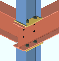
| Framing situations: Auto base/cap plates are generally designed to frame to a supporting or supported beam, or they can support a joist. They can be applied to wide flange , S shape , welded plate W , welded plate box , HSS rectangular or HSS round columns. | |
|
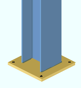
Forced or user defined auto base/cap plate. An ' Auto base/cap ' that is entered as " Input connection type " is changed to ' Plain end ' if the column does not frame to anything. To get the connection, you need to " |
|
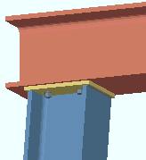
Example of an auto cap plate on a sloping column. Connection design can create auto cap plates if there is a beam above the column. If you want a cap plate or base plate, and there there is no beam above or below the column, you can " |
|
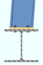
Auto base plate on a sloping column not in alignment with the beam. When the work lines of the column and beam are not in alignment, you'll get the following end connection failure message if the work point of the column is not centered on the beam flange: " Invalid offset column connection ." For an auto cap plate (not shown), the work point must go to the bottom flange of the beam. |
| Auto Cap Plate Welded to Vertical Brace Gusset | |
| Connection Design Locks = " Column Plate " | |
| Input connection type: ' Auto base/cap plate ' or ' Auto standard ' or ' User defined '. |
|
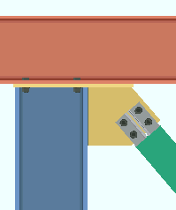
| Framing situations: When a vertical brace frames to a column with a cap plate or base plate, connection design welds the gusset to the column and the plate. | |
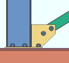
| Auto base plate welded to vertical brace gusset. In order to design an ' Auto base/cap plate ', connection design requires a column-to-beam framing situation. In this example, the bottom of the column frames to the beam, and connection design extends the base plate. |
|
| Column with User Base Plate | |
| Connection Design Locks = " Column Plate " | |
| Input connection type: ' User base/cap plate ' or ' Auto standard ' or ' User defined '. |

|
| Settings: A " Plate schedule number " entered on the column gets the plate from Home > Project Settings > Job > Base/Cap Plate Schedule . | |
| Comments: A ' User base/cap plate ' can be placed on a column that does not frame to anything. | |
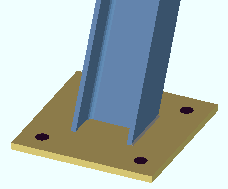
| Here's a user base plate on a sloping column. The base plate is centered with respect to the center line of the column. |
|
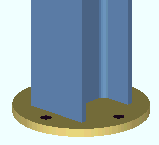
| A round user base plate. The hole pattern for a round base/cap plate is set on the Round Plate Holes screen that for the Base/Cap Plate Schedule. |
|
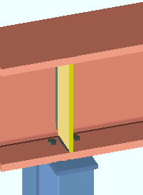
| Transverse Beam Stiffeners Designed with Base/Cap Plate | |
| Connection Design Locks = " Column Plate ," " Stiffener Plate " | |
|
Input connection type: ' Auto base/cap plate ' or ' User base/cap plate ' or ' Auto standard ' or ' User defined '. |
| Comments: Connection design creates a beam stiffener plate on a beam (under or over a column with a base/cap plate) if there is enough " Load " on the column. Setup options include: " Design transverse stiffeners for base/cap plate connection " and " Minimum beam stiffener plate thickness ." | |
|
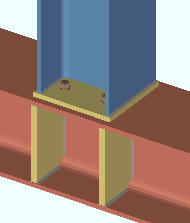
Another example of beam stiffeners: Two transverse beam stiffeners are designed when the " Load " on the column is large enough. In this example, beam stiffeners are designed for a beam that supports a column that has a base plate. |
|
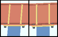
Transverse beam stiffeners aligned with the column. Connection design has a setup option for this. You can also set this for individual connections . |
|
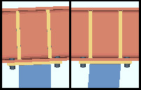
Transverse beam stiffeners aligned with the beam. Connection design has a setup option for this. You can also set this for individual connections . |
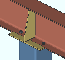
| Beam Bottom Flange Extension Plates with Tapered Stiffeners | |
| Connection Design Locks = " Bottom Extension Plates ", " Stiffener Plate " | |
|
Input connection type: ' User base/cap plate ' or ' Auto base/cap plate ' or ' Auto standard ' or ' User defined '. |
|
| Settings: " Use extended stiffeners " (' Yes ' or ' Automatic ', auto base/cap plate) or " |
|
| Comments: Home > Project Settings > Fabricator > Standard Fabricator Connections > Extended Flange Plate Settings sets up the initial design of the extension plates and stiffener. | |
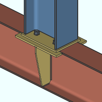
| Beam Top Flange Extension Plates with Tapered Stiffeners | |
| Connection Design Locks = " Top Extension Plates ", " Stiffener Plate " | |
|
Input connection type: ' User base/cap plate ' or ' Auto base/cap plate ' or ' Auto standard ' or ' User defined '. |
| Settings: " Use extended stiffeners " (' Yes ' or ' Automatic ', auto base/cap plate) or " Use extended stiffeners " (' Yes ' or ' Automatic ', user base/cap plate) | |
| Comments: Flange extension plates are designed to aid in the erection of a column whose column plate extends beyond the flange of a beam. Their purpose is not structural. | |
| Auto Cap Plate Supporting a Joist | |
| Connection Design Locks = " Column Plate " | |
| Input connection type: ' Auto base/cap plate ' or ' Auto standard ' or ' User defined '. |

|
| Framing situations: Auto base/cap plates can support a joist or a beam. | |
| Comments: The space between the joist and the cap plate is the joist's " Bearing depth ." | |
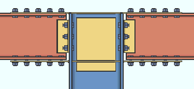
| Bolted Moment Cap Plate, Column with 'Plain end'
( ' Plain end ' on column ) |
|
|
|
| The connection on this column is a ' Plain end '. See " Bolted Moment Cap Plate " for more information. |
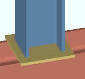
| User Base/Cap Plate to a Web Horizontal Beam | |
| Connection Design Locks = " Column Plate " | |
| Input connection type: ' User base/cap plate ' or ' Auto standard ' or ' User defined '. |
|
| Settings: ." Beam rotation " to ' 90 ' | |
| Comments: This is not a designed connection. The plate " Length " runs parallel with the beam workline. The base/cap plate is a ' User base/cap plate '. | |
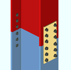
| Column Splice for Wide Flange Columns, Same Section Sizes | |
| Connection Design Locks = " Outer Flange Plate " | |
|
Input connection type: ' Splice plate ' or ' Auto standard ' or ' User defined '. |
| Settings: ' All-Bolted plates ' to column, no " Butt plate ." | |
| Comments: Splice plates shop bolt to the lower column. Columns must be wide flange, S shape or welded plate wide flange. | |
|
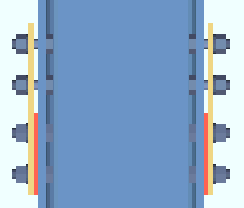
Another splice for wide flange columns with the same depth. Lower fill plates (red in this example) are designed on the lower shaft so that the " Minimum field clearance " specified in Column Splice Settings can be achieved. |
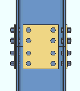
| Web Plates on Columns with Bolted Flange Splices | |
| Connection Design Locks = " Outer Flange Plate ," " Web Plate " | |
|
Input connection type: ' Splice plate ' or ' Auto standard ' or ' User defined '. |
| Settings: ' All-Bolted plates ' column attachment, " |
|
| Framing situations: Bolted flange splices are required to get the web splice plate. You won't get the web splice when connection design designs a butt plate (see below ). | |
|
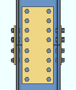
Another example of a web plates. These are the same two columns as in the illustration above. The connection was generated by increasing the " Horizontal shear " on both columns. Connection design automatically increased the plate thickness and number of rows of bolts to stand up to the increased load. |
| Column Splice for W Columns with Different Section Sizes | |
| Connection Design Locks = " Outer Flange Plate " | |
| Input connection type: ' Splice plate ' or ' Auto standard ' or ' User defined '. |
|
| Settings: ' All-Bolted plates ' column attachment. | |
| Comments: A butt plate and fill plates are designed if the upper column's nominal depth is at least 2 inches less than the lower column. | |
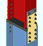
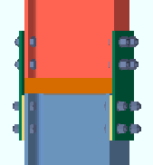
| An upper column that is deeper than the lower column. Upper column = ' W12x35 '; lower = ' W12x40 '. Since the upper column is deeper, connection design creates fill plates for the lower column. Connection design fails connections like this if the cross-sectional area of the upper column is greater than that of the lower column. |
|
| Field Welded Column Splices for HSS Rectangular Columns | |
| Connection Design Locks = " Butt Plate " | |
|
Input connection type: ' Splice plate ' or ' Auto standard ' or ' User defined '. |
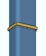
| Settings: ' Welded ' column attachment, " Butt plate " (checked in this example). | |
| Comments: Columns of other material types can also be field welded. The butt plate in this example is shop welded to the lower column. | |
| Field Welded Splice with Bolted Channel Web Connection | |
| Connection Design Locks = " Splice " | |
| Input connection type: ' Splice plate ' or ' Auto standard ' or ' User defined '. |
|
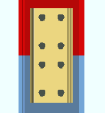
| Settings: ' Welded ' column attachment, " Channel web connection " (checked), ' Bolted ' to ' Near side ' (or ' Far side ' or ' Both sides ') of the lower column. | |
| Setup: Home > Project Settings > Fabricator > Std Fab Conns > Splice Plate Setup > " Channel splice section size selection " | |
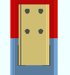
| Field Welded Splice with Welded Channel Web Connection | |
| Connection Design Locks = " Splice " | |
|
Input connection type: ' Splice plate ' or ' Auto standard ' or ' User defined '. |
| Settings: ' Welded ' column attachment, " Channel web connection " (checked), ' Bolted ' to ' Near side ' (or ' Far side ' or ' Both sides ') of the lower column. | |
| Setup: Fabricator Setup > Std Fab Conns > Splice Plate Setup > " Channel splice section size selection " | |


