The Column Edit window (or Column Edit -- Multiple or Column Review )
Also see :
|
|
|||||||||
|
|
||||||||
Section size: The column's main material (e.g., ' W12x45 ').
|
|
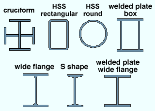
Wide flange , welded plate wide flange , S shape , welded plate box , HSS round (pipe), HSS rectangular (tube) and cruciform are acceptable shapes for which connection design can create the full range of " Input connection types ." Connections for braces and beams framing to these types of columns can usually, but not always, be designed (for example, the curved surface of a pipe column may make certain connections impractical). |
Invalid material types: If you enter a " Section size " that is not one of the "Valid Material Types for Column Connections" listed in the above chart, you will get the following end connection failure message :
Invalid material type for this member For cruciform, the steel grade(s) of the materials making up the cruciform section is set at Home > Project Settings > Job > Material Grades > Cruciform Grades . The " Steel grade " for section sizes other than cruciform is set here , on this window.
To enter a column section size: You can type in the section size that you want, or you can press the "file cabinet" browse button (
) and double-click any section that is on the list of available materials in the local shape file . Validation restricts you to entering a material that is listed in the local shape file. Also, if you enter a section size that is not available, a yes-no dialog opens with the warning, " The section size is not available from suppliers. Are you sure you want to use it? "
HSS10x625
HSS10x500
HSS10x375
HSS10x312
HSS10x250
HSS10x188

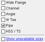
This selection dialog opens when you press the button. Because only "
Pipe " is checked, only round HSS and PIPE sections are listed.
Note: Column work lines (stick form member lines) are drawn through the neutral axis of a wide flange , welded plate wide flange , S shape , welded plate box , HSS round or HSS rectangular column.
To add/edit section sizes: Shapes Properties .
Required file for editing: The " Shape file " path must be set to the local shape file (press " Local ").
To copy section sizes from another shape file: Copy Shapes .Status Display: Member status > Member section size
Report Writer: Member.MaterialFile.SectionSize
Advanced Selection: m.SectionSize
Parametric module: m.SectionSize
Piecemark or System piecemark or User piecemark or Frozen piecemark :
Sequence :
Note this scenario: You are editing one column, which shares its piecemark with other columns. You change its sequence and other settings. If you press " Yes " when prompted " Do you want to change all... ," the changed sequence applies only to the one column you are editing, but the other settings are applied to all columns with the same piecemark.
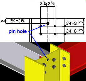
Erection pin hole: Automatic or Yes or No . An erection pin hole is a lift hole near the top of a column that can be used by a crane to lift the column into place.
|
When ' Automatic ' is selected, connection design prevents an erection pin hole from being created if the hole interferes with the clip angle on the beam. It does design one when ' Yes ' is selected. |
' Automatic ' generates an erection pin hole based on the selection made to Home > Project Settings > Fabricator > Member Detailing Settings > " Columns " section > " Show erection pin holes on columns ." Exception: Connection design may prevent a lift hole from being generated in order to avoid interference with a connection to the column.
' Yes ' centers a pin hole at the half-depth of the column. The pin hole is the diameter and edge distance (from the top of the column) specified in Member Detailing Settings . The pin hole will be generated even if it interferes with a connection to the column.
' No ' prevents a pin hole from being created -- regardless of the choice made in Member Detailing Settings .
Be aware that choosing ' No ' on this window is the only way to permanently remove an erection pin hole. You can temporarily erase an erection pin hole using Erase Hole , but the hole will return the next time the column undergoes Process and Create Solids -- for example, when you open this window and press " OK ."
Report Writer: Member.Settings.ColumnErectionPinHole
Report Writer: Member.Settings.AutoColumnErectionPinHole
Advanced Selection: m.ColumnErectionPinHole
Advanced Selection: m.AutoColumnErectionPinHole
Parametric module: m.ColumnErectionPinHole
Parametric module: m.AutoColumnErectionPinHole
Column rotation: A positive or negative number from 90 to - 90 degrees. ' 0 ' degrees orients the column according to the slope of a column (see the examples below). A ' positive number ' rotates the column counterclockwise from the zero position that number of degrees. A ' negative (-) number ' rotates the column clockwise from the zero position.
| A special case: For a welded plate wide flange column, which can have different-sized (unsymmetrical) flanges, the rotation can be from 0 to 360 degrees. Channels and cold form channel columns also behave this way. |
' 0 '
 |
' 45 '

|
' -45 '

|
' 90 '

|
| ' 0 ' degrees sets the web of a perfectly vertical column parallel with the X axis in a plan view. | |||
' 0 ' degrees
 |
' 0 ' degrees
 |
' 0 ' degrees
 |
| ' 0 ' degrees sets the web of a sloping column parallel to the X axis if, as in the left example, the slope of the column is along the X axis in a plan view. The middle example shows a column whose slope is along the Y axis in a plan view. | ||
Report Writer: Member.Rotation
Advanced Selection: m.Rotation
Parametric module: m.Rotation
Toe direction: In or Out . This " ![]() General settings " option applies when the column's " Section size " is channel or angle material.
General settings " option applies when the column's " Section size " is channel or angle material.
' In '

|
' Out '

|
' In ' (with " Long leg " = ' Normal ') points the leg of the angle or the toes of the channel toward the near side of the column. In other words, ' In ' points the toes down in a plan view (to the right if the " Column rotation " is ' 90 ').
' Out ' (with " Long leg " = ' Normal ') points the leg of the angle or the toes of the channel away from the near side of the column. Since a plan view looks at members from the bottom up (or right in for members whose webs are vertical in a plan view), selecting ' Out ' points the toes up (or to the left if the " Column rotation " is ' 90 ').
Note: ' In ' and ' Out ' are reversed when ' Reversed ' is selected for the " Long leg " of an angle.
Report Writer: Member.Settings.ToeIO
Advanced Selection: m.ToeIO
Parametric module: m.ToeIO
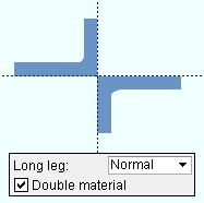
Configuration: Star or Back to back . This " ![]() General settings " option applies when the column's " Section size " is angle material and yes is selected for " Double material ."
General settings " option applies when the column's " Section size " is angle material and yes is selected for " Double material ."
' Star '
 |
' Back to back '
|
If ' Star ' is selected, the two angles will be laid out so that the outside corner of each angle is along the member line of the column and no legs are back to back.
If ' Back to back ' is selected, the two angles will be laid out so that one leg of each angle is back-to-back.
Advanced Selection: m.Configuration
Parametric module: m.Configuration
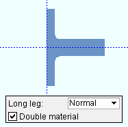
Long leg: Normal or Reversed . This " ![]() General settings " option applies when the column's " Section size " is angle material.
General settings " option applies when the column's " Section size " is angle material.
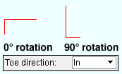
' Normal '
|
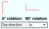
' Reversed '
|
Select ' Normal ' if you want the long leg of the angle to be horizontal in a plan view when ' 0 ' is entered as the " Column rotation ."
Select ' Reversed ' if you want the long leg of the angle to be vertical in a plan view when ' 0 ' is entered as the " Column rotation ."
Note: This option also affects the appearance of details of the column. The bottom of a column is the lower end on a column detail.
Advanced Selection: m.LongLegOfAngleIsVertical
Parametric module: m.LongLegOfAngleIsVertical
Double material: Yes or No . This " ![]() General settings " option applies when the column's " Section size " is a channel or cold formed channel or angle material.
General settings " option applies when the column's " Section size " is a channel or cold formed channel or angle material.
Yes

|
No

|
If yes, the column will be made up of two identical channel or angle sections of whatever " Section size " is entered. For channel double material, the two channels (or cold-formed channels) are back-to-back, as shown in the above illustration. For angle double material, the two angles are oriented with respect to one another and the column member line per the double-angle " Configuration " (' Star ' or ' Back to back ').
If no, the column will be made up of a single channel or angle " Section size ."
Report Writer: Member.Settings.DoubleMaterial
Advanced Selection: m.DoubleMaterial
Advanced Selection: m.DoubleMaterial
Welded section is single material: ![]() or
or ![]() . This "
. This " ![]() General settings " option applies when the column's " Section size " is a welded plate wide flange or welded plate box .
General settings " option applies when the column's " Section size " is a welded plate wide flange or welded plate box .
|
|
If this box is checked (
) when you auto detail the column, the member bill of material will list the welded plate wide flange or welded plate box section as a single section size. You can generate a separate submaterial detail for the section (but not for the plates that make up the section). On a member such as a rolled section miscellaneous member or a legacy miscellaneous member , which does not have the " Welded section is single material " option, welded plate sections are always treated as single material.
If the box is not checked (
) when you auto detail the column, the member bill of material will list the welded plate wide flange section as three plates (four plates for a welded plate box). You can generate separate submaterial details for the plates.
CNC for DSTV: Download plates (too) of welded sections
Report Writer: Member.Settings.WeldedSectionIsSingleMaterial
Sloped column: ![]() or
or ![]() . The box is checked automatically if you Add Column by locating two points that are not aligned vertically.
. The box is checked automatically if you Add Column by locating two points that are not aligned vertically.
If this box is checked (
), then Move/Stretch Members and Move/Stretch Members, Include Material are permitted to change the slope of the column when you have one end (
) of the column selected.
If the box is not checked (
), Move/Stretch Member is not permitted to make the column slope. Also, if the column is currently sloping and you uncheck this box then press " OK ," the column's top end work point aligns with the bottom end work point, thus making the column perfectly vertical.
Report Writer: Member.Settings.SlopedColumn
Break Apart : ![]() or
or ![]() .
.
------------------
Main material : ![]() or
or ![]() .
.
Marked for processing : ![]() or
or ![]() .
.
Marked for detailing : ![]() or
or ![]() .
.
Node-match job : ![]() or
or ![]() . ( read-only )
. ( read-only )
Model complete : ![]() or
or ![]() . ( read-only )
. ( read-only )
Model complete date : **NOT SET** or a month day year .
Lift assignment : not assigned or a crane placement name . ( read-only )
------------------
WP to WP length: Read-only . This " ![]() General settings " distance is the difference between the column's top and bottom " End elevation ." If the column is perfectly vertical, this is the actual length of the column's workline (in the primary dimension " Units ").
General settings " distance is the difference between the column's top and bottom " End elevation ." If the column is perfectly vertical, this is the actual length of the column's workline (in the primary dimension " Units ").
Tip: For a perfectly vertical column, subtracting the top- and bottom-end " Material setback " from the distance reported here gives you the length of the column main material.
Advanced Selection: m.WorkpointToWorkpointLevel (vertical columns)
Advanced Selection: m.WorkpointToWorkpointSlope (sloping columns)
Parametric module: m.WorkpointToWorkpointLevel (vertical columns)
Parametric module: m.WorkpointToWorkpointSlope (sloping columns)
------------------
| Special Buttons for Detailing | |||
|
|
|
|
|
| Press this button to open a window with a list of preset views that you can select. When you auto detail the column, each preset view is drawn on the detail. | Press this button to open a list of views you can delete. If the column has only a main view, you get a warning instead of a list of views since you cannot delete the main view. | This button opens the Annotations... window. Press " OK " on that window to detail the columns you are editing. Newly added views will be drawn on the detail. Deleted views will not be drawn. | Press this button to start up the Drawing Editor . You will automatically be shown the detail of the column if this column has been detailed and if the file is not currently open. |
The " Detail Member " button is enabled when you are multi-editing columns with different piecemarks, allowing you to auto detail those columns. The other buttons will be disabled ( grayed out ) for multi-edit operations, although you can " View detail " if the multiple columns being edited have the same mark.
Note 1: If you add or delete a view or detail this member using these buttons, the " Marked for detailing " button updates immediately.
Note 2: " Freeze drawing " in the Drawing Editor disables ( grays out ) the " Add View " " Delete View " and " Detail Member " buttons.
|
|
| The bottom end of a column is its left end . |
| End setting buttons : " Lock End " " Lock All Lockables "
" Save As User Defined Connection " " Copy " " Paste " " Save " " Load " |
disables ( grays out ) all options under [ Bottom end settings ] or [ Top end settings ] (as the case may be), thus preventing users from making changes to the connection.
" Copy " and " Save " form buttons remain active for the locked end. You are also still permitted to make changes to "
General settings " or to the other end's settings.
The material, hole, bolt and weld edit windows for system connection materials associated with this end of the member became read-only.
Furthermore, Delete or Erase cannot remove any of this connection's materials, holes, bolts or welds. Cut Layout , Add Holes , and similar material altering operations cannot be performed on any of the connection's materials. Such operations can only be performed on the member main material.
The member main material's setbacks and end preparations will become read-only.
Locking a member's end does not inhibit operations that you can normally perform on the member main material -- such as Cut Layout or Add Holes -- nor does it stop you from applying Custom Properties to the locked connection material.
allows the options under [ Bottom end settings ] or [ Top end settings ] to be edited.
Status Update: Lock left/right end
Status Display: Approval and modeling > Member left end locked
![]() /
/ ![]() " Lock All Lockables" / "Unlock All Lockables "
" Lock All Lockables" / "Unlock All Lockables "
|
sets all "
End preparations " and "
Connection design locks " under [ Bottom end settings ] or [ Top end settings ] (as the case may be) to a locked state, thus preventing the connection from being altered by connection design . You will still be able to make changes to the connection by unlocking (
) particular lockable fields (so that connection design can make entries to that field) or by you yourself making different entries to the locked fields.
unlocks all connection design locks associated with the top or bottom end (as the case may be). This results in a connection that is fully designed by connection design, without any user entries to connection design locks.
![]() Save As User Defined Connection: This button is available when you are editing one member at a time. It is not available if you are editing multiple columns. It allows you to save as a user defined connection changes that you have made to connection design locks and to other [ Bottom end settings ] or [ Top end settings ]. You can overwrite a previously saved user defined connection or create an entirely new user defined connection.
Save As User Defined Connection: This button is available when you are editing one member at a time. It is not available if you are editing multiple columns. It allows you to save as a user defined connection changes that you have made to connection design locks and to other [ Bottom end settings ] or [ Top end settings ]. You can overwrite a previously saved user defined connection or create an entirely new user defined connection.
1. When you are done adjusting the connection's settings, click the Save As User Defined Connection button.2. The Select one User Defined Connection window opens. Click the New... button to create a new user defined connection using the current Connection specifications, connection design locks, and Moment options you have set.
Alternative 1: To save over an existing user defined connection and replace its settings with the current settings of the edit window, select it and click OK or double-click it. Click Yes or No on the prompt window asking if you want to overwrite the connection. The user defined connection is immediately saved. There are no further steps to take.
Alternative 2: Click the Cancel button to close the Select one User Defined Connection window.
3. The User defined connection name input window opens. Type in a name for the connection (61 characters max.) and click OK to save the new user defined connection.
Alternative: Click the Cancel button to close the User defined connection name input window and return to the Select one User Defined Connection window.
![]() " Copy " " Paste " " Save " " Load "
" Copy " " Paste " " Save " " Load "
|
|
|||||||||
|
|
||||||||
Connection: Force and/or Graphical or a System connection . This " ![]() Information " option and its related messages apply when this column end's " Input connection type " is a choice other than ' Plain end ' or ' User base/cap plate '.
Information " option and its related messages apply when this column end's " Input connection type " is a choice other than ' Plain end ' or ' User base/cap plate '.
' Force ' applies when the connection has failed , which results in your not getting any connection materials in the 3D model.


forced 

system To get connection materials so that you can assess the situation and make needed changes, check the box for "
Force ." The Connection Design Calculations report (and Expanded Connection Design Calculations ) will include a warning that the connection has been forced. Example: Suppose you get the end connection failure message " No supporting member " instead of an auto base/cap plate. Checking the box for "
Force " is a possible way to get a solids model of the column plate. However, the connection that is designed will probably not be exactly what you want. Connection design locks under a leaf named "
Column Plate " can then be used to refine the connection to proper specifications.
' Graphical ' may have been automatically set to "
Graphical " as a result of a user employing modeling operations to modify the system connection on this end of the member, thus making it graphical .


graphical 

system A graphical connection will not be changed by connection design . On this window, you will not be able to change any of that connection's "
End preparations " and "
Connection design locks ." The Connection Design Calculations report (and Expanded Connection Design Calculations ) will include the warning " GRAPHICAL CONNECTION -- STRENGTH CALCULATIONS NOT GENERATED ." If "
Graphical " is checked and you switch it to "
Graphical " then press " OK " (so that Create Solids is performed), user-added modifications to that connection will be overwritten or erased. For example, user-added holes will disappear. On the General Information window for each of the connection materials, you will see that switching from "
Graphical " to "
Graphical " caused the connection materials that were regenerated to be changed from " User modified connection material " to " System created connection material ."
Search and Change:
- Graphical Connections (a search)
- Change Graphically Altered to System Connections
- Change System to Graphically Altered Connections
- Change Force to System Connections
Status Display: Search > Graphical connections
Report Writer: Member.LeftEnd.MoreEnd.Settings.ForceConnection
Report Writer: Member.LeftEnd.IsGraphicalConnectionAdvanced Selection: m.Ends[0].ForceConnection
Advanced Selection: m.Ends[0].IsGraphicalConnectionParametric module: m.Ends[0].ForceConnection
Parametric module: m.Ends[0].IsGraphicalConnection
" Connection design locks set ," connection failed messages, other messages :
If you are in a multi-user environment, a member edit window could be opened at the same time somebody else is adding a member that connects to that member. As a result, Process within member edit will be locked from accessing information about that open member, and the following message will be generated:
| On-the-fly process failed |
If you are editing multiple columns and those columns have different connection failed or connection changed messages, a banner like the following is displayed:
Multiple failed and/or changed connection messages The following banner notifies you that the connection has at least one "
Connection design lock " or "
End preparations " setting that is locked(
):
| Connection design locks set. |
|
Search: Connection design locks set
Status Display: Search > Connection design locks setSetting the User and Site Options > Modeling > " Process within member edit " to ' Off ' gets you the following banner:
The option "Process within member edit" has been disabled.
Values on this screen may change after process.You may find a red connection failure banner like that shown below along with a
button for context-sensitive help about the message.
| Invalid material type for this member |
|
|
|
for help on the failure message that is shown |
launches your " Help browser " and gives you context-sensitive help about an end connection failure message . A connection failure message may be generated, for example, due to "
Top/Bottom end limit state " analysis revealing that a connection cannot carry the load that the connection's member is subjected to. The various limit states associated with a connection are tested during connection design .
Report Writer: Member.LeftEnd.ConnectionhasFailed
Report Writer: Member.LeftEnd.MoreEnd.Conditions.ConnectionFailError
Advanced Selection: m.Ends[0].ConnectionHasFailed
Parametric module: m.Ends[0].ConnectionHasFailedOr you may find a green " Connection changed ... " banner that indicates connection design has deviated from settings entered by the user in order to create a connection that works.
| Conn changed. Possibly: Splice vs Plain end |
Tip: Compare this column end's "
Summary " and " Input connection type " and " System designed connection " and "
Connection specifications " to assess what has changed.
Also see: Search for Connections Changed by System .
You will find a yellow " Frames to ... " banner on this end of the column if this end of the column frames to a member that has its " Model complete date " set. The message (possible inaccurate connection) may be added to the banner, or connection design may fail the connection on this end (the banner end) with the error message: Frames to a Model Complete member .
Frames to a Model Complete member
(possible inaccurate connection)Model complete type: Restrictive or Legacy
Setup: Member and Drawing Restrictions
Also see: Lock Ends Framing to Model Complete Members
|
|
|||||||||
|
|
||||||||
To move between the " End elevation " under [ Top end settings ] and the " End elevation " under [ Bottom end settings ] , press the comma key ( , ) on your keyboard.
End elevation: The elevation (in the primary dimension " Units " or other units ) of the work point at this end of the column. The work point is at the bottom of the base plate or top of cap plate. On a column with a splice plate with a butt plate, the top work point of the lower column is the top of the butt plate. Changing the elevation affects the calculation of " WP to WP length ."
Important: For a change to the bottom-end " End elevation " of the column, the choice made to " Move material " will affect your results if the bottom-end " Connection " is set to "
Graphical " or the " Main material " has been set to '
' or a user has added holes or materials to the member.
Note 1: " Copy " " Paste " " Save " " Load " buttons do not operate on the " End elevation ."
Note 2: If you are editing one column with a piecemark shared by at least one other column and change its " End elevation " on one or both ends, you will get a notification dialog after you press " OK " to close this window. The notification dialog will remind you that you have the option to change the elevations of all columns with the same mark. If you choose to change the elevations of all columns with the same mark, the ends of the members will be moved in the same manner and by the same relative amount (not necessarily to the same elevation).
Note 3: If the column setup option " Show end elevations on details " is on, then changing the " End elevation " causes the column to be " Marked for detailing ."
Note 4: The choice made to User and Site Options > Modeling > " Classic column location for columns added/repeated in plan view " directly affects the default " End elevation " values for columns that are added/repeated in a plan view.
Tip: To determine the end elevation on a column in the 3D model, start up a tool such as Construction Line Add , select EXPT as the Locate option, then move the point location target to the work point at the end of a column and reference the Z coordinate reported in the X-Y-Z display .
Report Writer: Member.LeftEnd.LocationZ
Advanced Selection: m.Ends[0].Location.z
Parametric module: m.Ends[0].Location.z
Move material: ![]() or
or ![]() . This "
. This " ![]() Member " option applies only to vertical columns ("
Member " option applies only to vertical columns (" ![]() Sloped column "). It applies when the bottom-end " Connection " is set to "
Sloped column "). It applies when the bottom-end " Connection " is set to " ![]() Graphical " or the " Main material " has been set to '
Graphical " or the " Main material " has been set to ' ![]() ' or a user has added holes or materials to the member. In other words, it may apply when column has user-added holes, user modified connection material , user modified member main material or user created material .
' or a user has added holes or materials to the member. In other words, it may apply when column has user-added holes, user modified connection material , user modified member main material or user created material .
|
||||||
|
||||||
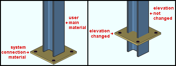
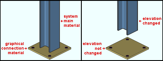
If this box is checked (
), the user-added or user-modified material (as well as holes) will move with the bottom end of the vertical column when the member's bottom-end " End elevation " is changed. In other words, the user material will behave like system connection material.
If the box is not checked (
), the user-added or user-modified material will remain in place when the member's bottom-end " End elevation " is changed.
Default: When this window first opens, the box for " Move Material " is checked (
) or not checked (
) based on the choice made to User and Site Options > Modeling > " Maintain user material and holes relation to vertical column/vertical brace member left end ."
Why only the bottom end: The " Move material " option is available only for the bottom end of a perfectly vertical column because the bottom end of such a column is the column's left end (end zero). In this program's code, user-added materials and holes are placed along a member based on their distance from the member's left end.
Also see: Move/Stretch Member, Include Material , Move material ( Vertical Brace Edit window, left end).
Minus dimension: Auto or a user-entered distance (in the primary dimension " Units " or other units ). The minus dimension is the distance from the work point to the face of the connection if the connection material extends past the end of a member (e.g., a column cap plate).
If the box for " Auto " is checked (
), then connection design checks the framing for beams running over (or under) the column, and the minus dimension will be calculated as required for the column to clear the beam.
If the box for " Auto " is not checked (
), then you can type in the distance . A positive minus dimension makes the column shorter; a negative (-) minus dimension lengthens the column by that amount.
Status Display: Member status > Auto minus dimension (either end)
Status Display: Member status > Left end minus dimension and Right end minus dimension
Material setback: Auto or a user-entered distance (in the primary dimension " Units " or other units ).
If the box for " Auto " is checked (
), then connection design calculates this dimension for you. For this setback to apply, this column end's " Input connection type " must be ' Plain end ' or ' User defined '.
If the box for " Auto " is not checked (
), you can type in the distance to bring the end of the column's main material that distance back from the work point. You might do this, for example, to adjust the length of the column main material without changing the " Minus dimension " (changing the " Minus dimension " would move the face of the cap plate).
Status Display: Member status > Auto material setback (either end)
Status Display: Member status > Left end material setback and Right end material setback
Status Display: Member status > Has input setback
Change: Input to AUTO Material Setback
Standard detail: None or a standard detail name . To apply a standard detail, either type in the name of the drawing (if you know it), or press the "file" browse button ( ![]() ) and select a job standard detail or global standard detail from the list.
) and select a job standard detail or global standard detail from the list.
If ' none ' is entered here, then no standard detail will be applied on this end of the column when it is automatically detailed .
If a ' standard detail name ' is entered here, the next time you automatically detail the column, the reference point of the standard detail will align with the input work point on this end of the column, and the standard detail's bill of material will be combined with the column's bill of material. The detail is placed on a layer that is named after the standard detail plus a " _T " or " _B " suffix.
Report Writer: Member.LeftEnd.MoreEnd.StandardDetailFileType
Report Writer: Member.LeftEnd.MoreEnd.StandardDetailFileNumber
Report Writer: Member.LeftEnd.MoreEnd.StandardDetailFileNameAdvanced Selection: m.Ends[0].StandardDetailFileNumber
Advanced Selection: m.Ends[0].StandardDetailFileTypeParametric module: m.Ends[0].StandardDetailFileNumber
Parametric module: m.Ends[0].StandardDetailFileType
|
|
|||||||||
|
|
||||||||
Input connection type: Auto standard or User defined or Plain end or Auto base/cap plate or User base/cap plate or Splice plate (column-to-column) or Clip angle or Shear .
| Input connection | Comments |
| ' Auto standard ' | Designs a system connection per the column end's framing condition . |
| ' User defined ' | Enter the user defined connection name to " User defined connection " (below). |
| ' Plain end ' | For when you do not want a system connection on this end of the column. Use Add Assembly or Add Material to build a connection. |
| ' Auto base/cap ' | Designs a base/cap plate for a column framing to (under or over) a beam. See " |
| ' User base/cap ' |
See " Plate schedule number " (below) and " |
| ' Splice plate ' |
Select " |
|
' Clip angle ' ' Shear ' |
These are hanger connections. They fail with the message " Hangar connections not supported ." " |
When you change this column end's " Input connection type ," previously set "
Connection specifications " and "
Connection design locks " are replaced with new, default settings.
Process within member edit takes place immediately, at the time that an " Input connection type " is entered.
"
Connection specifications " and "
Connection design locks " provide settings for finer control of a connection's design.
Report Writer: Member.LeftEnd.MoreEnd.InputConnection.TypeDescription
Advanced Selection: m.Ends[0].Input.TypeDescription
Parametric module: m.Ends[0].Input.TypeDescription
Also see: The Connection Guide
User defined connection: The file name of the user defined connection in your current Job that you want applied when this column end's " Input connection type " is ' User defined '.
To make an entry, you can type in the file name of the user defined connection that you want (if you know it), or you can press the "file cabinet" browse button (
) and double-click any user defined connection file name that is on the list.
Status Display: Connection type > Specific user defined connection
Report Writer: Member.Conditions.HasAUserDefinedConnection
Advanced Selection: m.Ends[0].FinalConnectionIsUserDefined
Parametric module: m.Ends[0].FinalConnectionIsUserDefined
Plate schedule number: The line number of the Base/Cap Plate Schedule for the plate you want applied on this end of the column. This applies when this column end's " Input connection type " is ' User base/cap plate '.
|
To make an entry, you can type in the line number that you want (if you know it), or you can press the "file cabinet" browse button (
) and double-click any plate that is on the representation of the Base/Cap Plate Schedule that appears on screen.
Advanced Selection: m.Ends[0].PlateScheduleNumber
Parametric module: m.Ends[0].PlateScheduleNumber
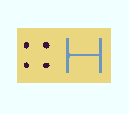
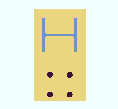
Plate rotation: A positive or negative number of degrees.
0 degrees
 |
90 degrees
 |
180 degrees 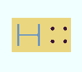 |
A positive number rotates the user base/cap plate counterclockwise.
A negative (-) number rotates the user base/cap plate clockwise.
Note: If you have entered an " Offset parallel to web " and/or an " Offset parallel to flange ," then " Rotation " is around the point defined by those offsets.
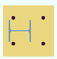
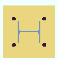
Offset parallel to web: The positive or negative distance (in the primary dimension " Units " or other units ) that you want the base/cap to be offset from the center of the column. The direction of the offset is parallel with the web of the column (the column's Y member axis ).
6 inches
 |
0 inches
 |
- 6 inches
 |
A positive distance moves the base/cap plate to the right (in a plan view) when both the " Plate rotation " and " Column rotation " are ' 0 '. It moves the base/cap plate up (in a plan view) when the " Column rotation " is ' 90 ' and the " Plate rotation " is ' 0 '.
0 (zero) keeps the base/cap plate centered on the column.
A negative (-) distance moves the base/cap plate to the right (in a plan view) when both the " Plate rotation " and " Column rotation " are ' 0 '. It moves the base/cap plate down (in a plan view) when the " Column rotation " is ' 90 ' and the " Plate rotation " is ' 0 '.
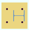
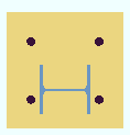
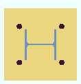
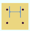
Offset parallel to flange: The positive or negative distance (in the primary dimension " Units " or other units ) that you want the base/cap to be offset from the center of the column. The direction of the offset is parallel with the flanges of the column (the column's Z member axis ).
6 inches
 |
0 inches
 |
- 6 inches
 |
A positive distance moves the base/cap plate up (in a plan view) when both the " Plate rotation " and " Column rotation " are ' 0 '. It moves the base/cap plate to the left (in a plan view) when the " Column rotation " is ' 90 ' and the " Plate rotation " is ' 0 '.
0 (zero) keeps the base/cap plate centered on the column.
A negative (-) distance moves the base/cap plate down (in a plan view) when both the " Plate rotation " and " Column rotation " are ' 0 '. It moves the base/cap plate to the right (in a plan view) when the " Column rotation " is ' 90 ' and the " Plate rotation " is ' 0 '.
System designed connection: Read-only . The type of connection that connection design created on this end of the column (e.g., ' Splice plate ' or ' Plain end ' or etc.). If a non-auto standard connection has failed , resulting in no solids model being created, the connection type that the connection design last attempted to design will still be reported here. This column end's " System designed connection " may be different than its " Input connection type " in the following situations:
If ' User defined ' or ' Auto standard ' is the selected " Input connection type ," the specific designed connection type is reported here. Press the " Design Calc " or " Expanded Calc " button for more information about that connection.
When an auto standard connection has failed , the connection type reported here is ' Plain end '.
Report Writer: Member.LeftEnd.MoreEnd.DesignedConnection.TypeDescription
Advanced Selection: m.Ends[0].Designed.TypeDescription
Parametric module: m.Ends[0].Designed.TypeDescription
NM bolt type: Auto or A325N or A325SC or A325X or etc. NM stands for "non-moment. This bolt type is used when ' Splice plate ' or ' Auto base/cap plate ' is the " System designed connection ."
'
Auto (checked) ' instructs connection design to use the non-moment " Bolt type " set at Home > Project Settings > Job > Bolt Settings for connections other than auto standard. For auto standard connections, connection design applies the " NM bolt type " set at Home > Project Settings > Job > Auto Standard Connections for that particular connection and framing condition.
'
Auto (not checked) ' lets you select a bolt type from the list box (
). Bolt types that are listed come from Home > Project Settings > Job > Bolt Specifications .
Advanced Selection: m.Ends[0].ConnectionDesignBoltTypeDescription
Advanced Selection: m.Ends[0].NonMomentBoltTypeWasInput
Parametric module: m.Ends[0].ConnectionDesignBoltTypeDescription
Parametric module: m.Ends[0].NonMomentBoltTypeWasInput
NM bolt diameter: Auto or a user-entered diameter (inches or mm). This " ![]() Connection type " option sets the diameter of the shanks of the bolts that are generated when ' Splice plate ' or ' Auto base/cap plate ' is this column end's " System designed connection ."
Connection type " option sets the diameter of the shanks of the bolts that are generated when ' Splice plate ' or ' Auto base/cap plate ' is this column end's " System designed connection ."
| diameter |
|
'
Auto (checked) ' instructs connection design to use the non-moment " Bolt diameter " set at Home > Project Settings > Job > Bolt Settings for connections other than auto standard. For auto standard connections, connection design applies the " NM bolt diameter " set at Home > Project Settings > Job > Auto Standard Connections for the particular connection and framing condition.
'
Auto (not checked) ' lets you either type in the diameter of bolt, or select a bolt from the combo box (
). The bolts that are listed in the combo box come from the " Available bolts " setup list.
Bolt spacings: The spacing between rows of bolts in a splice plate connection is set by the " Bolt spacing " per bolt diameter at Home > Project Settings > Fabricator > Connection Detailing/Fabricator Options .
Report Writer: Member.LeftEnd.MoreEnd.MinimumNonMomentBoltDiameter
Advanced Selection: m.Ends[0].MinimumNonMomentBoltDiameter
Parametric module: m.Ends[0].MinimumNonMomentBoltDiameter
Use miscellaneous plates list: ![]() or
or ![]() .
.
If this box is checked (
), connection design looks to Home > Project Settings > Fabricator > Standard Fabricator Connections > Preferred Plate Sizes to determine the plate thicknesses to be used for auto base/cap plates , transverse beam stiffeners , flange splice plates , butt plates and web splice plates . First connection design calculates the thickness of the plate required to stand up to the load, then it chooses a plate from the list that is the calculated required thickness or the next thicker. If the plate from the list results in material interferences or too narrow a clearance, connection design fails the connection and gives you the failure message, " Suitable plate thickness not found ."
If the box is not checked (
), connection design rounds the calculated required thickness of plates as based on the load to the next 1/16 inch (or 1/8 inch if the calculated required thickness is greater than 5/16 inch).
Exceptions and related settings: Fill plates for column splices are designed to exact thicknesses so that they fill the available space. The Base/Cap Plate Schedule sets thicknesses for user base/cap plates. The " Minimum beam stiffener plate thickness " affects beam stiffener thickness.
Report Writer: Member.LeftEnd.MoreEnd.UseMiscellaneousPlates
Disable framing situation checks: ![]() or
or ![]() .
.
If this box is checked (
), framing situation checks are turned off.
If the box is not checked (
), framing situation checks are turned on.
Advanced Selection: m.Ends[0].MarkedToCheckFramingSituation
Parametric module: m.Ends[0].MarkedToCheckFramingSituation
|
|
||||||||||
|
|
|||||||||
"
Connection specifications " is populated with options when this column end's " Input connection type " is ' Splice plate ' or ' Auto base/cap plate ' or ' User base/cap plate ' or ' Clip angle ' or ' Shear '. There are no "
Connection specifications " options -- just an empty leaf -- when the " Input connection type " is ' Auto Standard ' or ' User defined ' or ' Plain end '.
For more information, click a link :
----- Splice plate ----
| Column attachment | Channel lower connection |
| Butt plate | Channel connection side |
| Web plates | Splice plate grade |
| Channel web connection | Inner flange plates |
----- Auto base/cap plate ----
| Weld pattern | Use extended stiffeners |
| Use transverse beam stiffener | Base/cap plate grade |
| Align stiffeners with |
----- User base/cap plate ----
| Weld all around | Use transverse beam stiffener |
| Flange welds | Align stiffeners with |
| Web welds | Use extended stiffeners |
| Seal welds |
--- Clip angle ---
(Fails with " Hangar connections not supported " message.)
(" ![]() Force " can get you a solids model.)
Force " can get you a solids model.)
| Gage | Stagger on |
| Attachment | Use expanded vertical bolt spacing |
| Side | Use paddle plate |
| Attached to | Skew holes in angle |
--- Shear ---
(Fails with " Hangar connections not supported " message.)
(" ![]() Force " can get you a solids model.)
Force " can get you a solids model.)
| Attached to | Skew holes in plate |
| Shear plate side | Use back-up bar |
| Use expanded vertical bolt spacing | Shear plate grade |
| Use paddle plate |
|
|
|||||||||
|
|
||||||||
Warning : Loads entered here affect the design of column end connections and beam stiffeners. Users should enter loads only at the direction of a qualified engineer.
Load ( kips or kN ): Auto or a user-entered load in kips (kilonewtons for ' Metric '). This value reflects the force that is directed toward the connection, compression. The load is used for connection design of auto base/cap plates and splice plates . If stiffeners are desired in beams over or under columns with base/cap plates, a load must be entered for the column end that contacts the beam ( Exception: see " Design transverse stiffeners for base/cap plate connection "). If there are columns below and above a beam, enter a load for only one of the columns. The load entered determines the necessity for one pair of stiffeners or two pairs. The stiffeners will be at least the " Minimum stiffener plate thickness " entered in Plate Criteria . For column splices, connection design attempts to synchronize the design load on each of two columns being spliced so that they are the same values. If one column has an " ![]() Auto " load and the other column has a user-entered load, the load on both columns are set equal to the user-entered " Load ." If both columns have user-entered loads and those loads are not the same, the connection fails. If both columns have "
Auto " load and the other column has a user-entered load, the load on both columns are set equal to the user-entered " Load ." If both columns have user-entered loads and those loads are not the same, the connection fails. If both columns have " ![]() Auto " loads, connection design uses the smaller of the two calculated loads.
Auto " loads, connection design uses the smaller of the two calculated loads.
| Load: |
|
|
| or | ||
| Load: |
|
|
If the box for " Auto " is checked (
), the load is calculated automatically. The calculated value -- calculated in this example -- is shown in grayed-out text to indicate that it cannot be changed so long as "
Auto " is checked. Design method considerations: For ' ASD ' or ' LRFD ' and ' CISC 8 ' or ' CISC 9 ' and for base/cap plates in ' AS 4100 ', the "
Auto " load is the column's capacity in compression, calculated assuming the column has an effective length of zero. For splice connections in ' AS 4100 ', the "
Auto " compression load is 15% of the column's capacity in compression, calculated assuming it has an effective length of zero, plus the bearing capacity between the two columns.
If the box for " Auto " is not checked (
), you may enter a load. See the warning above.
Status Display: Member status > Left end compression load and Right end compression load
Status Display: Connection auto loads > Auto column load
End connection failure message: User entered loads at splice must match
Also see: " Show design loads on column detail ."
Tie force ( kN ): 0 (zero) or a user-entered load (in kips for ' Imperial ', kilonewtons for ' Metric ').This " ![]() Loads " option is available for most " Connection design method s."
Loads " option is available for most " Connection design method s."
An entry of ' 0 ' (zero) prevents connection design from using the tying force in its calculations for the design of a connection on this end of the column.
A ' user-entered load ' instructs connection design to use this tying force to check the structural integrity of a splice connection on this end of the column, as required by Section 1615 of the International Building Code (2015) for high-rise buildings.
Moment ( kip-in or kN-m ): Auto or a user-entered load in kips-inches (kilonewton-meters for ' Metric '). Moment loads are used for connection design of column splices only.
| Moment: |
|
|
| or | ||
| Moment: |
|
|
If the box for " Auto " is checked (
) for the spliced ends on two columns being spliced, a small, non-zero moment is used in the connection design of the column splice. The calculated numerical value -- calculated in this example -- is shown in grayed-out text to indicate that it, the calculated moment value, cannot be changed so long as "
Auto " is checked. Design method considerations: For ' ASD ' or ' LRFD ', the "
Auto "' moment load is taken as 6 kips for ASD (10 kips for LRFD) times the depth of the section. For ' CISC 8 ' or ' CISC 9 ', it is 10 kips (44.48 kN) times the depth of the section. For ' AS 4100 ', it is 30% of the section's moment capacity calculated in accordance with Clause 5.2.
If the box for " Auto " is not checked (
), you may enter the moment to be used in the design of the column splice. If the other column being spliced has an "
Auto " moment, connection design uses the value you enter here for both columns. If the two columns have different moment, the connection fails. See the warning above.
Status Display: Member status > Left end moment load and Right end moment load
Status Display: Connection auto loads > Auto column moment
End connection failure message: User entered loads at splice must match
Advanced Selection: m.Ends[0].AutoMomentLoad
Advanced Selection: m.Ends[0].MomentForce
Parametric module: m.Ends[0].AutoMomentLoad
Parametric module: m.Ends[0].MomentForce
Weak axis moment ( kip-in or kN-m ): 0 (zero) or a user-entered load in kips-inches (kilonewton-meters for ' Metric '). Weak axis moment loads are used for connection design of column splices only. The load is applied about the weak axis of the column (also referred to as the minor principal centroidal axis of the column cross section). If the two columns in a splice connection have a different moment, the connection fails. See the warning above.
" Input connection type " must be " Splice plate ": This "
Loads " option is disabled when this column end's " Input connection type " is ' User defined ', ' Plain end ', ' Auto base/cap plate ', or ' User base/cap plate '.
End connection failure message:User entered loads at splice must match
Advanced Selection: m.Ends[0].WeakAxisMomentLoad
Parametric module: m.Ends[0].WeakAxisMomentLoad
Splice uplift ( kips or kN ): Auto or a user-entered load in kips (kilonewtons for ' Metric '). " Splice uplift " is used in design calculations for column splices only. The value entered here quantifies the force directed upward, resulting from tension in the upper column.
| Splice uplift: |
|
|
| or | ||
| Splice uplift: |
|
|
If the box for " Auto " is checked (
) for the spliced ends on two columns being spliced, then connection design enters a minimum load of 6 kips for ' ASD ' or 10 kips for ' LRFD ' or ' CISC 8 ' or ' CISC 9 ' or 40 kN for ' AS 4100 '. For connections other than splice plates, the load is set to 0. The calculated numerical value -- calculated in this example -- is shown in grayed-out text to indicate that it, the calculated uplift value, cannot be changed so long as "
Auto " is checked.
If the box for " Auto " is not checked (
), you may enter a load. If the other column being spliced has an "
Auto " load, connection design uses the value you enter for both columns. If the two columns have different loads, the connection fails. See the warning above.
" Input connection type " must be ' Splice plate ": This "
Loads " option is disabled when this column end's " Input connection type " is ' User defined ', ' Plain end ', ' Auto base/cap plate ', or ' User base/cap plate '. If the " Input connection type " is ' Auto Standard ' and a value is entered for " Splice uplift " and a base/cap plate is specified in Auto Standard Connections for the framing situation, a connection will not be designed, and you will get the following connection failure message: Uplift load not applicable to this connection .
Status Display: Connection auto loads > Auto column splice uplift
End connection failure message: Uplift load not applicable to this connection
End connection failure message: User entered loads at splice must match
Horizontal shear: Auto or a user-entered load in kips (kilonewtons for ' Metric '). This " ![]() Loads " option applies when this column end's " Input connection type " is ' Splice plate '. It applies to the design of " Web plates ."
Loads " option applies when this column end's " Input connection type " is ' Splice plate '. It applies to the design of " Web plates ."
| Horizontal shear: |
|
|
| or | ||
| Horizontal shear: |
|
|
If the box for " Auto " is checked (
), then connection design sets the load to 0 or to match the load that is entered on the opposing column end that this end of this column splices to.
If the box for " Auto " is not checked (
), you may enter a load. See the warning above. The load that is entered here governs the plate thickness and number of bolts on " Web plates ."
Status Display: Connection auto loads > Auto column horizontal shear
End connection failure message: User entered loads at splice must match
|
|
|||||||||||
|
|
||||||||||
A " ![]() Summary " appears on this window only if you are editing one column. There is no "
Summary " appears on this window only if you are editing one column. There is no " ![]() Summary " leaf if you are editing multiple columns.
Summary " leaf if you are editing multiple columns.
Advanced Selection: m.PiecemarkCount
Parametric module: m.PiecemarkCount
|
|
|||||||||||
|
|
||||||||||
|
End preparation settings that are similar to these can be found on the Rolled Section Material window. However, those settings cause the " Main material " to be set to '
' and the affected " Connection " to be "
Graphical ".
These settings keep the " Main material " set to '
' and do not make the connection graphical.
Top flange operation : ' None ' or ' Cope plain ' or ' Cope field weld #3 (Standard) ' or ' Cope shop weld #3 (Standard) ' or ' Cut flange width ' or ' Cut flange flush ' or ' Clip flange ' or ' Notch Top/Bottom ' or ' Notch near side/far side ' or ' Cope field weld #1 (FEMA) ' or ' Cope shop weld #1 (FEMA) ' or ' Clip web ' or ' Seismic cope field weld ' or ' Seismic cope shop weld '.
|
|
|||||||||||||
|
|
||||||||||||
Column Plate ( auto base/cap, to a beam or joist )
Column Plate ( auto, no framing situation -- forced )
Stiffener Plate ( beam stiffeners for auto or user base/cap plates )
Top / Bottom Extension Plates ( auto base/cap plate )
Column Plate Welds ( auto or user base/cap plate ) (
)
Column Plate ( user base/cap, to a beam or a joist )
Column Plate ( user base/cap, no framing situation )
Left/Right/Top/Bottom Base Plate Extension ( user base/cap ) (
)
Additional Holes ( user base/cap )
Outer Flange Plate ( column flange splice plate connection )
Upper Outer Flange Fill Plate ( column flange splice plate connection )
Butt Plate ( column flange splice plate connection )
Web Plate ( column splice )
Upper Web Fill Plate ( column splice )
Web Channel ( for column spices that are field welded )
Status Display: Search > Connection design locks set
Search: Connection design locks set .
Design Calculations Report: Connection Design Lock Summary
|
|
|||||||||||||||
|
|
||||||||||||||
|
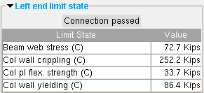
The limit states for an auto base plate. The values shown represent the allowable strength of the connection or of the column or a connecting beam. |
|
| HSS wall crippling failure under cap plate |
|
|
|||||||||||||||
|
|
||||||||||||||
- The following custom components are distributed with SDS2, and you therefore can potentially find on the Column Edit window a section for them with one of the following names:
Beam Stiffeners at Column Safety Tabs - Column HSS Cap Plates Base Plate Shear Key Safety Holes - Column Column Stiffeners - Column Base or Cap Plate Stiffeners Surfaces Connection Void Space Cylinder Void Space Layout
"Copy" "Paste" "Save" "Load" apply to all fields on this window. They do the same thing as the "Copy" "Paste" "Save" "Load" buttons ( ![]() ) found in the header portion of individual leaves on this window -- except that they apply to the entire window instead of just an individual leaf or section.
) found in the header portion of individual leaves on this window -- except that they apply to the entire window instead of just an individual leaf or section.
"Properties" opens the Edit Properties window, on which you can make entries to custom properties . If, at the time it was created, your current Job was set to use a legacy flavor, the window that opens is named Custom Properties , not Edit Properties .
The Edit Properties window can also be used to read "
Log " entries or review or type "
Notes ."
Tip: Model > Member > Properties is an alternative to this button. It opens the Edit Properties window directly, without your first having to open a member edit window.
" Status " opens the Member Status Review window, which can give you additional information about the columns you are editing, and which you can use to enter status information or designate a member as an " Existing member ."
Note: This button is orange if one or more " Repeat " check boxes on the Member Status Review window do not match the checked-unchecked state of same-named fields in User and Site Options > Site > " Member status items to Copy/Repeat ." On the Status Review window, the fields that do not match User and Site Options are printed in red .
" OK " (or the Enter key) closes the Column Edit window and saves any changes you have made on the window to the 3D model of your current Job .
Solids on "OK": If the appropriate choice is made to User and Site Options > Modeling > " Automatically process after modeling operation ," then this member will automatically be regenerated ( Create Solids will take place) after your press " OK ." Otherwise, you will have to manually Process and Create Solids in order for changes you made on this window to be fully updated in the 3D model.
Change all: If you Edit Member (one member only) and make a change that potentially triggers the " Do you want to change all ... " dialog and the 3D model contains more than one column that has the same piecemark as the column you changed, a yes-no dialog opens. On it is the question, " Do you want to change all (members with this piecemark). " Press the " Yes " button to change all the members; press the " No " button to change only this column. Special cases are listed on the table below:
| Do not trigger change all ... | Not changed with change all ... |
| " Sequence " | " Sequence " |
| " Piecemark " | " Toe direction " |
| " Member category " | " Column rotation " |
| " Member description " | " Loads " settings |
| " Member routes " | " Model complete date " |
| " Model complete date " |
Option to lock ends of framing members: If you changed the " Model complete date " on this column and other members have connections to this member, the Lock Ends Framing to Model Complete Members window opens, giving you options to "
Lock ... " the ends of those members that frame to this member.
Defaults for to-be-added columns: If you are adding a member and press " OK ," the settings on this window become the default settings for the next column you Add in this session of Modeling . Even if all you do is double-click a column and press " OK " without making any changes on this window, this window's settings become the defaults for the next-added column. On the other hand, the settings on this window do not become the defaults for new columns if you are editing multiple piecemarks or if you press " Cancel " to close this window.
" Cancel " (or the Esc key or the ![]() button) closes this window without saving any changes. " Cancel " does not undo a " Detail Member " operation.
button) closes this window without saving any changes. " Cancel " does not undo a " Detail Member " operation.
Note: If you opened this window using Add Column , pressing " Cancel " brings you back to the work point location step of adding a column.
Tip: Any time you Edit Member just to review a member (and you do not want to set the defaults for to-be-added members), the best way to close this window is to press " Cancel. "
" Reset " undoes all changes made to this window since you first opened it. The window remains open.
Exception: " Reset " does not undo a " Detail Member " operation.
"Design Calc" outputs the Design Calculations report (also referred to as Short Calcs) which includes design calculations, general settings, and left/right end settings. A report for each column you are editing is output to a destination of your choice as a PDF file. The file automatically opens with your operating system's default PDF application when you are editing one column at a time.
"Expanded Calc" outputs the Expanded Connection Design Calculations . First a PDF of the report is output to a destination of your choice. For example, to your desktop. Then the report automatically opens with your operating system's default PDF application.
Expanded Connection Design Calculations give you the calculation results found in the Connection Design Calculations , plus show you the calculations written out, in detail, in the report itself, instead of simply reporting the results.
If you are editing multiple columns with the same piecemark (or different piecemarks), you get a report for each column.
Connection design failures can be found with the aid of a search or by a quick scan of the document. Calculations that result in a connection failure are identified as " (NO GOOD) " in their concluding line. You might also search for the string "CONNECTION DESIGN FAILURE".
