"  Gusset 2 Point Square " & " Brace Connection To Gusset " & " HB Conn2 "
| Angle horizontal braces field bolt to a shared gusset per " |
|
|||||
| " (gusset plate dimensions and location) 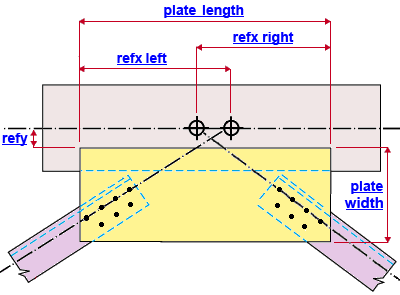 |
" (field bolt holes in the brace and gusset) 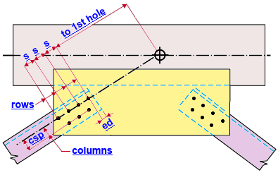 |
||||
| " (shop weld, gusset to the beam's top flange) 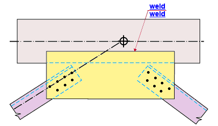 |
|
||||
Connection Guide: Click here for related screen shots.
User Defined Connections: Settings that are locked (
) in a user defined connection file will automatically be locked on a member edit window for which that file is the " Input connection type ." You can, if you so choose, manually lock additional settings on the member edit window, and your changes will be retained, through multiple processes, so long as you do not change to a different connection then switch back to the original user defined connection.
Horizontal Brace Edit: To change a setting, first set it to locked (
) may be updated, and the "
Connection design locks :
| Locks not dimensioned or called out on the drawings are marked ( not depicted ). |
![]() Gusset 2 Point Square
Gusset 2 Point Square
( angle horizontal braces, 2- or 3-point )
Gusset 2 Point Square
Plate thickness ( not depicted ): The distance between the two faces of the gusset plate. The " Material thickness " of the gusset plate.
Plate length: The length of the framing edge of the gusset plate (which welds to the flange of the supporting beam -- see example ). Plate length is measured parallel with the work line of the beam.
Plate width: The distance (perpendicular to the beam's work line ) between the two longest edges of the gusset plate (see example ). " Plate width " can also be defined as the length of either one of the two edges of the shared gusset plate that are perpendicular to the work line of the beam.
Refy : The distance (perpendicular to the supporting beam's work line ) from the work point of the horizontal brace to the framing edge of the gusset plate (which welds to the beam's top flange -- see example ). Changing the " Refy " moves the plate only, not the holes on the plate.
Left Brace [member number]
| Note: The member number [num] of the left horizontal brace is shown in brackets [num] in the heading for this section. |
Refx ( refx left ): The distance (parallel with the supporting beam's work line ) from the work point of the left horizontal brace to the left corner of the gusset plate's framing edge (the edge that shop welds to the beam's top flange -- see example ). Changing the " Refx " moves the plate only, not the holes on the plate.
Right Brace [member number]
| Note: The member number [num] of the right horizontal brace is shown in brackets [num] in the heading for this section. |
Refx ( refx right ): The distance (parallel with the supporting beam's work line ) from the work point of the right horizontal brace to the right corner of the gusset plate's framing edge (the edge that shop welds to the beam's top flange -- see example ). Changing the " Refx " moves the plate only, not the holes on the plate.
![]() Brace Connection To Gusset
Brace Connection To Gusset
( angle horizontal braces, 2- or 3-point )
Bolt diameter ( not depicted ): You can either type in any diameter (inches or mm), or you can select a bolt diameter from the combo box (
). The diameters that are listed in the combo box come from Home > Project Settings > Job > Bolt Settings > the " Available bolts " list. The bolt diameter entered here, together with the " Hole type " entered below, set the diameter of the holes the field bolts go into.
Hole type ( not depicted ): Standard round or Short slot or Oversized or Long slot or User slot #1 or User slot #2 . This sets the type of hole through which field bolts will fasten the braces to the gusset plate.

Rows: A number of holes ( 0 to 63 ) in the column of holes with the greatest number of holes. For an angle horizontal brace with staggered holes, this is the number of rows of holes in the column of holes along the work line of the brace. For an angle brace with non-staggered holes, this is the number of rows in any one column of holes. Entering ' 0 ' removes the holes. For either angle brace shown in the example above, the number of " Rows " is ' 4 '.
Distance to 1st hole along brace ( to 1st hole ): The distance (parallel with the work line of the horizontal brace) from the work point to the center of the nearest row of holes. See the example .
Hole spacing along brace ( s ): Row spacing. This is the distance (center to center) between any two adjacent holes in the same column of holes (see example ). Row spacing on a horizontal brace gusset plate runs parallel with the work line of the horizontal brace. Holes within an individual row run perpendicular to the work line.
End connection failure message: Invalid bolt spacing
Edge distance along brace ( edge dist ): The distance from the edge of the brace material that is nearest the brace work point to the center of the first hole in that same material. This distance is measured parallel with the work line of the horizontal brace. See the example .
Columns: The number of columns of holes in the half of the gusset that is being edited (see example ). For both horizontal braces in the example above, the number of " Columns " is ' 2 '.
Distance to 1st hole perpendicular to brace ( not depicted ): The distance from the work line of the horizontal brace perpendicular to the nearest column of holes. In the example above, this distance would be ' 0 ' (zero) since the nearest column of holes aligns with the work line of the brace.
Hole spacing perpendicular to brace ( csp ): Column spacing. This is the distance (center to center) between any two adjacent columns of holes in the half of the gusset being edited (see example ). Bolt column spacing runs perpendicular to the work line of the horizontal brace. Holes within an individual column run parallel with the work line.
![]() Brace Connection To Gusset
Brace Connection To Gusset
(angle horizontal braces, 2- or 3-point, gusset-to-beam shop weld)
Weld size ( weld ): The weld size used to shop weld the framing edge of the gusset plate to the top flange of the beam. This is also the weld size used to weld the under side of the gusset plate to the forward edge of the beam's top flange, which is shown with a blue dashed line ( - - - - - ) in the example . Shared gusset plates are detailed with the beam and field bolted to the braces.

