Horizontal Brace End Connection Failure Messages ( Modeling )
Messages listed in alphabetical order :
| A | B | C | E | F | G | H | I | L | M |
| N | P | S | T | U | W |
Where/when/why these error messages appear :
When you open a Horizontal Brace Edit window after connection design has failed an " Input connection type " connection on the left or right end of the horizontal brace, you will find a connection design error message such the following:
| Invalid brace work point location |
The message is displayed on the left half of the Horizontal Brace Edit window if it applies to the connection on the left end of the horizontal brace. The message tells you why connection design failed the connection. Understanding the message can help you to determine what steps you need to take in order to create the connection you want.
Changing connection design locks or other settings on a Horizontal Brace Edit window triggers Process within member edit. When adjusting member edit window settings to "fix" a connection, please heed the following warnings.
Warning 1: Users should enter loads (" Tension load ," " Compression Load ," etc.) only under the authority of a qualified engineer. An improperly set load can result in design changes that are structurally unsound. Lowering the load may get you a connection, but it could result in a connection failure under the true loading conditions in the built structure.
Warning 2: Make design changes (such as changing the brace's " Section size " or " Steel grade ") only under the authority of a qualified structural designer. Making such design changes may involve extra costs, clearance problems, delays, etc. For many projects, materials may have already been ordered at the time connections are being designed.
Warning 3: Creating graphical connections is a method to get around connection failures. Make sure that each graphical connection is approved by a qualified designer before its drawing is sent to the fabrication shop.
Warning 4: Fixing connection failures may, in some cases, involve making changes to Job/Fabricator Option files. Use great caution when you make such changes and always be prepared to later undo those changes. To apply such changes, a good procedure is to Mark for Processing any members that you want changed, then Process and Create Solids .
Warning 5: Just because connection design passes a connection without a failure message, you should not assume that the connection is optimal. All connections should be visually inspected in the model -- and this is especially true of braces since they are never changed during the frame checking phase of Process . In addition, the Connection Design Calculations or Expanded Connection Design Calculations report should be reviewed by a qualified engineer. To check for material interference problems, a Clash Report can help.
- A -
All 3 braces must have the same material type: You get this message when connection design fails a shared gusset for three braces when the " Section size " for at least one of the horizontal braces is a wide flange or tube brace.
Connection design can create shared gussets for a combination of angle or channel or W tee braces, but will not let you mix wide flange or tube braces with other material types.
To get a system connection , try changing the " Section size " so that each of the three braces are same type (wide flange or tube) or so that none of the three braces are wide flanges or tubes.
Before attempting to fix this connection, see the warnings .
- B -
Bolt bearing strength on conn./supported member exceeded: This connection failure message may apply when the horizontal brace end's " Input connection type " is ' Hbrc plate ' or ' User defined '. and the horizontal brace gusset plate connects to the supporting beam with a clip angle.
|
Framing situations
|
Horizontal brace to a beam's web |
| Horizontal brace perpendicular to a beam | |
| 2-point, to a web | |
| Horizontal brace to a beam-beam corner | |
| Horizontal brace to a beam-column -beam corner |
The connection failure message may be generated due to a user-made entry to the locked (
) field " Bolt diameter " or " Rows " (of bolts) or " Columns " (of bolts) for the leg to the gusset plate in a "
HB Conn2 " or "
Assuming that the horizontal brace's " Tension load " and " Compression load " are to engineering specifications, generally the best way to clear this failure message is to unlock (
) the " Bolt diameter " or " Rows " or " Columns " or, alternatively, to adjust the entries made to those locked fields..
Before attempting to fix this connection, see the warnings .
Bolt bearing strength on OSL/Supporting member exceeded: This connection failure message may apply when the horizontal brace end's " Input connection type " is ' Hbrc plate ' or ' User defined ' and the horizontal brace gusset plate bolts to the supporting beam with a clip angle.
|
Framing situations
|
Horizontal brace to a beam's web |
| Horizontal brace perpendicular to a beam | |
| 2-point, to a web | |
| Horizontal brace to a beam-beam corner | |
| Horizontal brace to a beam-column -beam corner |
The connection failure message may be generated due to a user-made entry to the locked (
Assuming that the horizontal brace's " Tension load " and " Compression load " are to engineering specifications, generally the best way to clear this failure message is to unlock (
Before attempting to fix this connection, see the warnings .
Bolt bearing strength on gusset/connection exceeded: This failure message applies when the " Input connection type " is ' Hbrc plate ' or ' User defined ' and the " Gusset to beam connection " is ' Clip angle '. It may be generated for any " Connection design method ." The failure occurs when bearing on either the gusset or the clip angle exceeds the limit.
| Framing Situation | Leaves Containing Relevant Locks |
| HBrc to a beam's web | NS/FS Clip Conn2 , Gusset One Member |
| HBrc perpendicular to a beam web | NS/FS Clip Conn2 , Gusset One Member Perp |
| 2-point bracing to a beam web | NS/FS Clip Conn2 , Gusset 2 Point |
| HBrc to two beam webs | Clip Angle & NS/FS Clip Conn2 ,
Gusset To Two Beams |
| HBrc to 2 beams, interposed column | NS/FS Clip Conn1 & NS/FS Clip Conn2 ,
Gusset To Two Beams |
The connection failure message may be generated due to a user-made entry to the locked (
Assuming that the horizontal brace end's " Tension load " and " Compression load " are to engineering specifications, generally the best way to clear this failure message is to unlock (
Before attempting to fix this connection, see the warnings .
Bolt diameter is greater than 1 inch; 25.4 mm:
| No longer applies! |
Prior to v2018, connection design had prevented horizontal brace gusset plates from being designed using bolt diameters greater than 1 inch (25.4 mm). That design check has been removed, and this connection failure message no longer applies.
Bolt dia. too large for member or sprt member flg: This applies to the brace-to-gusset bolts on angle , tee , and wide flange horizontal braces. Connection design checks the edge distance and the bolt clearance. If it determines that the brace-to-gusset bolts are too large in diameter for the brace, the connection fails, and you get this message.
To get the originally specified " Input connection type " connection, try entering a smaller " NM bolt diameter ." If that doesn't work, you'll probably need to enter a larger brace " Section size ."
Before attempting to fix this connection, see the warnings .
Bolt shear strength at OSL connection exceeded: This failure message applies when the " Input connection type " is ' Hbrc plate ' or ' User defined ' and the brace bolts to two beam webs with clip angles. It indicates that the strength of field bolts in the leg of the clip angle to the beam web has been exceeded.
| Horizontal Brace to Two Beams | |
| framing situation | leaves ( gusset clips, web ) |
| horizontal brace to beam-beam corner | NS/FS Clip Conn1 or NS/FS Clip Conn2 |
| horizontal brace to beam-column-beam | NS/FS Clip Conn1 or NS/FS Clip Conn2 |
The message may be generated due to user-made entries to locked (
Assuming that the " Tension load " and " Compression load " are to engineering specifications, the best way to clear the failure message is increase the " Bolt diameter " or number of " Bolt rows " or to unlock (
Before attempting to fix this connection, see the warnings .
Bolt shear strength at gusset connection exceeded: This failure message applies when the " Input connection type " is ' Hbrc plate ' or ' User defined ' and the brace bolts to two beam webs with clip angles. It indicates that the strength of shop bolts in the leg of the clip angle that connects to the gusset plate has been exceeded.
| Horizontal Brace to Two Beams | |
| framing situation | leaves ( gusset clips, web ) |
| horizontal brace to beam-beam corner | NS/FS Clip Conn1 or NS/FS Clip Conn2 |
| horizontal brace to beam-column-beam | NS/FS Clip Conn1 or NS/FS Clip Conn2 |
The message may be generated due to user-made entries to locked (
Assuming that the " Tension load " and " Compression load " are to engineering specifications, the best way to clear the failure message is increase the " Bolt diameter " or number of " Bolt rows " or to unlock (
Before attempting to fix this connection, see the warnings .
Bolt shear strength exceeded: This connection failure message can apply to any horizontal brace end's " Input connection type " that is bolted. The message may be generated for any " Connection design method ."
The connection failure message may be generated on the Horizontal Brace Edit window due to a user-made entry to locked (
Assuming that the horizontal brace's " Tension load " and " Compression load " and other parameters are to engineering specifications, generally the best way to clear this failure message is to unlock (
Before attempting to fix this connection, see the warnings .
Both braces must be either on/off the neutral axis: You get this failure message for angle and double angle horizontal braces that frame opposite to one another at a brace intersection plate . It indicates that the two braces have different " Locate on neutral axis " settings.
To fix this problem, change the " Locate on neutral axis " setting for one of the braces so that it matches the setting for the brace that is opposite to it on the intersection plate.
Before attempting to fix this connection, see the warnings .
Both braces must have the same material type: You get this failure message when connection design is unable to create an intersection plate or a shared gusset for horizontal braces of different material types.
To fix this problem, enter a new " Section size " for one or both braces so that both braces have section sizes that are of the same material type.
Before attempting to fix this connection, see the warnings .
Brace clip angle cannot be welded to beam and shipped with gusset: You can get this connection failure message when the horizontal brace " Input connection type " is ' HBrc plate ' or ' User defined ' and -- in " ![]() Connection specifications " -- the " Gusset to beam connection " is set to ' Clip angle '.
Connection specifications " -- the " Gusset to beam connection " is set to ' Clip angle '.
This failure message is emitted when -- in "
To clear this failure message and create a gusset clip angle that shop welds to the supporting beam, keep " Beam to clip connection " set to ' Welded ' and reset " Gusset clips on " to ' On supporting '.
Another way to clear this connection failure message is to change " Beam to clip connection " to ' Bolted ' and keep " Gusset clips on" set to ' On gusset '. The beam-to-clip bolts will, as a result, be field bolts .
Before attempting to fix this connection, see the warnings .
Brace clip angle cannot be welded to both beam and gusset: You can get this connection failure message when the horizontal brace " Input connection type " is ' HBrc plate ' or ' User defined ' and -- in " ![]() Connection specifications " -- the " Gusset to beam connection " is set to ' Clip angle '.
Connection specifications " -- the " Gusset to beam connection " is set to ' Clip angle '.
Connection design cannot design a welded-welded gusset-to-beam clip angle. This failure message is emitted when " Gusset to clip connection " and " Beam to clip connection " in the horizontal brace's "
To clear the connection failure message, change " Gusset to clip connection " or " Beam to clip connection " to ' Bolted '. Alternatively, you can change settings at Home > Project Settings > Fabricator > Member Detailing Settings > " Horizontal Braces: Clip angle of gusset " that make ' Automatic ' settings in "
Before attempting to fix this connection, see the warnings .
Brace clip angle cannot be welded to gusset and shipped with beam: You can get this connection failure message when the horizontal brace " Input connection type " is ' HBrc plate ' or ' User defined ' and -- in " ![]() Connection specifications " -- the " Gusset to beam connection " is set to ' Clip angle '.
Connection specifications " -- the " Gusset to beam connection " is set to ' Clip angle '.
The connection design failure message is emitted when -- in "
To clear the message and get a horizontal brace gusset clip angle that shop welds to the gusset, keep " Gusset to clip connection " set to ' Welded ' and set " Attach clip to " to ' On gusset '.
Another way clear the message is to set the " Gusset to clip connection " to ' Bolted ' and keep " Attach clip to " set to ' On supporting '. The gusset-to-clip-angle interface will be field bolted if the gusset ships with the brace, shop bolted if both the gusset clip angle and the gusset ship with beam.
Before attempting to fix this connection, see the warnings .
Brace clip angle connecting to single wflg beam cannot be welded: You can get this connection failure message when a horizontal brace frames to a wide flange beam and the horizontal brace " Input connection type " is ' HBrc plate ' or ' User defined ' and -- in " ![]() Connection specifications " -- the " Gusset to beam connection " is set to ' Clip angle '.
Connection specifications " -- the " Gusset to beam connection " is set to ' Clip angle '.
A horizontal brace gusset clip angle can weld to a HSS/TS or channel beam, but not to a wide flange, welded plate wide flange or S shape beam. This connection design failure message is emitted when -- in "
To clear the failure message, change " Beam to clip connection " to ' Bolted '. Alternatively, adjust choices made at Home > Project Settings > Fabricator > Member Detailing Settings > " Horizontal Braces: Clip angle of gusset " so that ' Automatic ' in "
Before attempting to fix this connection, see the warnings .
Brace clip angle must be welded to and shipped with hss beam: You can get this connection failure message when a horizontal brace frames to an HSS/TS beam and the horizontal brace " Input connection type " is ' HBrc plate ' or ' User defined ' and -- in " ![]() Connection specifications " -- the " Gusset to beam connection " is set to ' Clip angle '.
Connection specifications " -- the " Gusset to beam connection " is set to ' Clip angle '.
Connection design cannot bolt a horizontal brace gusset clip angle to a beam whose " Section size " is an HSS/TS section. The clip angle needs to be shop welded to the beam and shipped with the beam. This connection design failure message can be emitted when " Beam to clip connection " is set to ' Bolted ' and/or " Attach clip to " is set to ' On gusset '.
To clear the failure message, set " Beam to clip connection " to ' Welded ' and " Attach clip to " to ' On supporting '. Alternatively, adjust choices made at Home > Project Settings > Fabricator > Member Detailing Settings > " Horizontal Braces: Clip angle of gusset " so that ' Automatic ' in "
Before attempting to fix this connection, see the warnings .
Brace conn. will not fit in beam web: You get this failure message when connection design is unable to design a gusset plate for a horizontal brace framing into a beam web that is not deep enough.
To get the originally specified " Input connection type " connection, you will have to change the beam " Section size " or, possibly, relocate the brace with respect to the beam.
Before attempting to fix this connection, see the warnings .
Brace gross compression strength failure: You get this failure message when connection design cannot create a connection because the compression load causes failure of the brace.
Possible ways to get the originally specified " Input connection type " connection are to input a stronger " Section size " for the brace, or to lower the " Compression load " on the brace.
Before attempting to fix this connection, see the warnings .
Brace gross tension strength fails: You get this failure message when connection design cannot create a connection because the brace material itself is not strong enough to not stand up to the applied tension.
One way to get the originally specified " Input connection type " connection is to change to a different brace material. For example, it the brace is a single angle, you might change to " Double material ." If the brace is a tee, you might use a heavier tee " Section size ."
Another way is lower the " Tension load " and thus allow the brace to be as weak as it currently is.
Before attempting to fix this connection, see the warnings .
Brace net tension strength fails: You get this failure message when connection design has determined that the brace material, including the holes for bolting it to the gusset, is not strong enough to stand up to the applied tension.
Possible ways to get the originally specified " Input connection type " connection are to change to a different brace material (e.g. if it's a brace of single angle material, you might change to " Double material "; if it's made of tee material, you might use heavier tee " Section size "), or to lower the " Tension load " and thus design a weaker gusset plate.
Before attempting to fix this connection, see the warnings .
Braces must be colinear: This failure message applies to angle and double angle and HSS horizontal braces that frame opposite to one another at a brace intersection plate . It indicates that the work lines (stick form lines) of the two braces are not in alignment.
To evaluate the misalignment of the two braces, use EXPT to locate a construction line that passes through the work points of one of the opposing horizontal brace. Then do the same for the opposite horizontal brace. You will see that the construction lines (and therefore the two horizontal braces) are not colinear.
To fix this problem, you may be able to change the " End elevation " of one of the horizontal braces so that it is colinear with the opposite horizontal brace. If that doesn't work, you can use Move/Stretch Members or Move/Stretch Members, Include Material to repair the problem. Or you may have to Erase the member then Add a new horizontal brace.
Before attempting to fix this connection, see the warnings .
Brace not in a parallel plane of either supporting beam: The flanges of each beam that supports a horizontal brace need to be parallel in on order for connection design to create horizontal brace connections to those beams. This means that you either need to rotate the beams or reposition one or both brace work points.
Before attempting to fix this connection, see the warnings .
Braces have different end elevations: You get this connection failure message when connection design cannot create a shared gusset for horizontal braces because the braces are at different elevations.
To get the originally specified " Input connection type " connection, adjust the " End elevation " on both ends of one brace so that it matches the " End elevation " of the other brace.
Before attempting to fix this connection, see the warnings .
- C -
Calculated minus dim larger than member length: This connection failure message indicates that an entry made to a connection design lock on the brace would result in the " Automatic minus dimension " being larger than the member length, which is a physical impossibility that cannot be accurately modeled.
A possible fix that will make the connection failure message go away is to unlock (
Another possible fix is to keep the lock (
Before attempting to fix this connection, see the warnings .
Clip angle/plate weld strength to gusset exceeded: This failure message applies when the " Input connection type " is ' Hbrc plate ' or ' User defined '. The horizontal brace gusset may weld directly to the supporting beam or it may connect to the supporting beam with a clip angle. This message may be generated for any " Connection design method " and applies to virtually all horizontal brace framing situations.
The connection failure message may be generated due to a user-made entry to the locked (
Assuming that the " Tension load " and " Compression load " are to engineering specifications and that the " Gusset plate grade " is what you want it to be, probably the best way to clear this failure message is to unlock (
Before attempting to fix this connection, see the warnings .
Clip angle with adequate thickness not available: You get this connection failure message when an angle section that will work for this connection is unavailable in the local shape file .
Possible ways to get the originally specified " Input connection type " connection are to add the angle you need using Shapes Properties , or use a different section size for the brace or supporting member. Lowering the " Tension load " may allow connection design to use an angle that is less thick.
Before attempting to fix this connection, see the warnings .
Cannot complete connection design: This may apply to many different situations.
You should probably review the 3D model with an eye toward examining this particular framing situation in order to assess what might be the problem.
Before attempting to fix this connection, see the warnings .
Cannot have a moment web setback with both flanges coped: This connection failure message indicates that both the " Top flange operation " and the " Bottom flange operation " on the same member end are cope operations and a non-zero " Moment connection web setback " has been set. Various cope operations can be specified under the " ![]() End preparations " leaf on a member edit window.
End preparations " leaf on a member edit window.
|
|
To clear this failure message, you can clear the cope operation on either the top flange or the bottom flange or enter ' 0 ' to " Moment connection web setback " or unlock (
If you do not clear this failure message, connection design will still cope the top and bottom flanges. However, the " Moment connection web setback " that you have entered will not be applied. That entry will still be shown on the member edit window, accompanied by this failure message as an indication that the entered distance has not been applied. On the Rolled Section Material window, the " Moment connection web setback " will be ' 0 ' since zero will be the actual, applied setback.
Cannot have a moment web setback without a cope weld end operation: This failure message applies to all member types that have a valid " Section size " to which you can apply a cope weld end operation.
|
|
To clear this failure message, you need to enter ' 0 ' to " Moment connection web setback " or unlock (
If you do not clear this failure message, connection design will still apply any " Top/bottom flange operation " that you have specified. The entry that you have made to " Moment connection web setback " will still be shown on the member edit window, accompanied by this failure message as an indication that the entered distance has not been applied. On the Rolled Section Material window, the " Moment connection web setback " will be ' 0 ' since zero will be the actual, applied setback.
Combined gusset stress limit exceeded: This failure message applies when the " Input connection type " is ' Hbrc plate ' or ' User defined '. For example, it may apply to the framing situations listed below. It may be generated for any " Connection design method ." The failure message indicates that combined forces from the beam and brace exceed the gusset plate stress limit.
| Framing situations: | Horizontal brace to a beam's web |
| Horizontal brace perpendicular to a beam | |
| 2- and 3-point | |
| Horizontal brace to a beam-beam corner | |
| Horizontal brace to a beam-column -beam corner |
The connection failure message may be generated due to a user-made entry to the locked (
Assuming that the " Shear load " on the beam and the " Tension load " and " Compression load " on the horizontal brace are to engineering specifications, the best way to clear this failure message is to unlock (
Before attempting to fix this connection, see the warnings .
Connecting beam has failed connection: You get this connection failure message because the beam to which the horizontal brace is connecting has a connection failure. This message might, for instance, occur on a brace connecting to a beam-column-beam or to a beam-beam .
Before connection design can create a gusset plate, you need to get a system connection on the end of the beam. See beam connection failure messages .
Before attempting to fix this connection, see the warnings .
Connection will not fit in beam: You can get this end connection failure message on a horizontal brace framing into a beam web. If the beam is not deep enough, connection design cannot generate a gusset plate on this end of the brace.
To get the originally specified " Input connection type " connection, you will have to change the beam " Section size " or, possibly, relocate the brace with respect to the beam.
This is a geometry problem where you should probably review the 3D model and inspect the framing situation before you make your decision.
Before attempting to fix this connection, see the warnings .
Conn modified by framing situation, see design calc: If you get this failure message, probably your best course of action is to press the " Expanded Calc " button at the bottom of the Horizontal Brace Edit window and review the report that is output. In the Expanded Calculations Report , calculations that result in a connection failure are identified as " (NO GOOD) " in their concluding line. You might also search for the string "CONNECTION DESIGN FAILURE".
One possible way to clear this message is to check the box for " Disable framing situation checks " However, that will most likely result in a different failure message being generated.
Before attempting to fix this connection, see the warnings .
Cope depth is less than minimum allowed: This failure message applies when, under the " ![]() End preparations " leaf on a member edit window, you have entered a " Cope depth " that is less than the minimum allowed. A " Cope depth " can be entered for any of the following " Top/bottom flange operations :"
End preparations " leaf on a member edit window, you have entered a " Cope depth " that is less than the minimum allowed. A " Cope depth " can be entered for any of the following " Top/bottom flange operations :"
|
|
Connection design calculates the minimum cope depth based on the flange thickness of the " Section size " of the member, using in the following formula: r + tf + 0.01 inch = mcd .
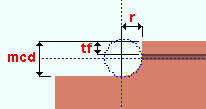
mcd = minimum cope depth
tf = flange thickness
r = cope radiusTo clear this failure message, you need to enter a " Cope depth " that is larger than the calculated minimum ( mcd ) or unlock (
End operation will not work with this situation: This connection failure message indicates that the left- or right-end " Top flange operation " or " Bottom flange operation " under " ![]() End preparations " on the member edit window will not work. This is a catch-all failure message. In the table below, situations that produce this failure message ( 289 ) are marked ? or fail .
End preparations " on the member edit window will not work. This is a catch-all failure message. In the table below, situations that produce this failure message ( 289 ) are marked ? or fail .
| OK = end operation is applicable to the material type. | ||||||
| fail = end operation will not work for this situation ( 289 ). | ||||||
| ? = operation works on the flange, not the stem. | ||||||
| 288 = failure message number 288. | ||||||
| W , S | C | L | tube | pipe | WT | |
| Cope plain | OK | OK | OK | OK | OK | OK |
| Cope field #3 | OK | OK | ? | fail | fail | ? |
| Cope shop #3 | OK | OK | ? | fail | fail | ? |
| Cut flange width | OK | 288 | 288 | fail | fail | fail |
| Cut flange flush | OK | 288 | 288 | fail | fail | fail |
| Clip flange | OK | fail | fail | fail | fail | fail |
| Notch top/bottom | fail | fail | fail | OK | OK | fail |
| Notch NS/FS | fail | fail | fail | OK | OK | fail |
| Cope field #1 | OK | OK | ? | fail | fail | ? |
| Cope shop #1 | OK | OK | ? | fail | fail | ? |
| Clip web | OK | OK | OK | fail | fail | OK |
| Cope field seismic | OK | OK | ? | fail | fail | ? |
| Cope shop seismic | OK | OK | ? | fail | fail | ? |
Example of ?: Selecting ' Cope field weld #3 ' as the " Bottom flange operation " for a W tee horizontal brace produces the failure message, and a weld preparation will not be applied to the stem of the W tee. However, if you select the same operation as the " Top flange operation ," the weld preparation will be applied to the top flange of the W tee and, of course, you will not get the failure message. All operations in the above chart that are marked ? work in a similar way.
To clear the failure message, switch to a different " Top/bottom flange operation ."
- F -
Frames to a Model Complete member: This applies when the member this horizontal brace frames to has its " Model complete date " set.
You will get a yellow " Frames to ... " banner like the following even if there is no connection failure. This banner describes the framing situation, but does not necessarily pertain to connection design. For more information, click here .
| Frames to a Model Complete member |
In addition to the above banner, you may (but will not necessarily) get a red banner like the following, which indicates a connection failure due to connection design not being permitted to modify the main material of the model-complete member. This can happen, for example, if this horizontal brace was added, or its " Input connection type " or " Connection specifications " were changed, after the framed-to member's " Model complete date " was set.
Frames to a Model Complete member You can "
Force " the connection or change the model complete type on the model complete member from ' Restrictive ' to ' Legacy ', but the connection will probably not be designed correctly. Before connection design can generate a properly designed connection on this end of the horizontal brace, you need to type in ' 0 ' (zero) to enter ' **NOT SET** ' in place of the date entry for " Model complete date " on the member that this brace frames to. See the following table:
framing situation likely cause horizontal brace to beam flange The beam has its " Model complete date " set. horizontal brace to beam web The beam has its " Model complete date " set. horizontal brace with shared gusset The opposite horizontal brace or supporting beam has its " Model complete date " set. horizontal brace to beam-beam corner Either beam has its " Model complete date " set. horizontal brace X or T intersection The supporting horizontal brace has its " Model complete date " set.
- G -
Gusset-beam interface connection failure: You get this connection failure message for a horizontal brace framing to two beams. It indicates that the gusset bolted to the beam flange or clip angle bolted to the beam web has failed.
You should probably review the 3D model with an eye toward examining this particular framing situation in order to assess what might be the problem. For example, the geometry of the cut around the column may be the source of the problem.
Before attempting to fix this connection, see the warnings .
Gusset buckling strength exceeded: This failure message applies when the " Input connection type " is ' Hbrc plate ' or ' User defined '. It applies to virtually any horizontal brace framing situation. It may be generated for any " Connection design method ." It indicates that the compression load exceeds the buckling strength of the gusset plate.
The connection failure message may be generated due to user-made entries to locked (
Assuming that the applied " Compression load " is to engineering specifications, the best way to clear this failure message is to adjust the gusset plate's " Plate thickness " or to unlock (
Before attempting to fix this connection, see the warnings .
Gusset/clip angle tension strength exceeded: This failure message applies when the " Input connection type " is ' Hbrc plate ' or ' User defined '. It applies to virtually any horizontal brace framing condition. It may be generated for any " Connection design method ." The message indicates that the tensile strength of either the gusset plate or the clip angle connection to that gusset plate has been exceeded.
The connection failure message may be generated due to user-made entries to locked (
Assuming that the applied " Tension load " is to engineering specifications and the clip angle section size is what you want, the best way to clear this failure message is to adjust the gusset plate's " Length " or " Width " or " Plate thickness " or to unlock (
Before attempting to fix this connection, see the warnings .
Gusset connection angle not found: This connection failure message indicates that connection design could not find a connection angle that would allow it to complete the connection design.
When looking for a connection angle, connection design searches the local shape file . Lowering the " Tension load " may allow connection design to use a different angle.
Before attempting to fix this connection, see the warnings .
Gusset extends past center of supporting beam flange: This applies to a horizontal brace to two beam flanges or to two beam flanges with an interposed column .
The connection design check that produces this error message prevents gusset plates of horizontal braces that frame to the same beam flange from clashing into one another. You may get the error message even if there is no other horizontal brace framing opposite.
Typically you will get this error message only if you are using a fairly large " NM bolt diameter ." This is because a larger " NM bolt diameter " results in connection design applying a larger " Minimum edge distance ," which in turn causes the gusset plate to extend past the center of the top flange of the beam.
To get the originally specified " Input connection type " connection, you could try using a smaller " NM bolt diameter ." Or you could keep the same bolt diameter and change the " Minimum edge distance " for that diameter in Gusset Plate Settings .
Or you could "
Before attempting to fix this connection, see the warnings .
Gusset geometry fails: This connection failure message could indicate many different problems.
You should probably review the 3D model with an eye toward examining this particular framing situation in order to assess what might be the problem. The brace might be too small, or its work points may have been input incorrectly. To get the originally specified " Input connection type " connection, you may have Erase the brace then Add it again so that the brace properly connects with the beam. Or you may be able to select the offending member end (
) of the horizontal brace, then Move/Stretch Members or Move/Stretch Members, Include Material to repair the problem.
Before attempting to fix this connection, see the warnings .
Gusset gross/net shear strength exceeded: This failure message applies when the " Input connection type " is ' Hbrc plate ' or ' User defined ' and the horizontal brace gusset connects to a beam-beam corner or beam-column-beam corner with clip angles. The failure message may be generated for any " Connection design method ." It indicates that the shear strength of the gusset plate is insufficient.
| Horizontal Brace To Beam-Beam | ||
| brace mtrl | gusset | clip angle |
| angle | Gusset To Two Beams Square | Clip Angle or NS/FS Clip Conn2 |
| HSS | Gusset To Two Beams | NS/FS ClipConn1 or NS/FS Clip Conn2 |
| W, WT, 2L | Gusset To Two Beams Square | NS/FS Clip Conn1 or NS/FS Clip Conn2 |
| Horizontal Brace To Beam-Column-Beam | ||
| brace mtrl | gusset | clip angle |
| angle | Gusset To Two Beams Square | NS/FS Clip Conn1 or NS/FS Clip Conn2 |
| HSS | Gusset To Two Beams | NS/FS Clip Conn1 or NS/FS Clip Conn2 |
| W, WT, 2L | Gusset To Two Beams Square | NS/FS Clip Conn1 or NS/FS Clip Conn2 |
The connection failure message may be generated due to an entry that the user has made to the locked (
Assuming that the " Tension load " and " Compression load " are to engineering specifications and that the " Gusset plate grade " is what you want it to be, probably the best way to clear this failure message is to unlock (
Before attempting to fix this connection, see the warnings .
Gusset interactive stress limit exceeded: This failure message applies when the " Input connection type " is ' Hbrc plate ' or ' User defined ' and two or three braces share the same gusset plate. It may be generated for any " Connection design method ." The failure occurs when the gusset force interaction from two or three braces exceeds the limit.
| 2- or 3-Point Horizontal Brace Gusset Plate Locks | |
| framing situation | leaf containing relevant locks |
| HBrc to a beam's top flange (angle) | Gusset 2 Point Square |
| HBrc to a beam's web (angle) | Gusset 2 Point Square |
| HBrc to a beam's top flange (HSS) | Gusset 2 Point |
| HBrc to a beam's web (HSS) | Gusset 2 Point |
| HBrc to a beam's top flange (W, WT, 2L) | Gusset 2 Point Square |
| HBrc to a beam's web (W, WT, 2L) | Gusset 2 Point Square |
The connection failure message may be generated due to an entry that the user has made to the locked (
Assuming that the " Tension load " and " Compression load " on the two or three braces are to engineering specifications and that the " Gusset plate grade " is what you want it to be, the best way to clear this failure message is to unlock (
Before attempting to fix this connection, see the warnings .
Gusset interferes with beam connection: This applies when a horizontal brace to a beam web is too close to the supporting beam's end. If connection design were able to generate a gusset plate for this condition, the result would be a gusset plate that clashes with the connection (for example, the leg of the clip angle) on the beam.
The work point of the horizontal brace is too close to the end of the beam. To get the originally specified " Input connection type " connection, you need to Erase the horizontal brace then Add it again, this time locating the brace farther from the end of the beam. Or you may be able to select the offending member end (
Eurocode : If the " Connection design method " is ' EUROCODE 3 ' or ' EUROCODE 3 UK ' and the beam connection is an end plate, then you could try turning on (checking) the option "
Tip: You can "
Before attempting to fix this connection, see the warnings .
Gusset strength Whitmore section exceeded: This failure message applies when the " Input connection type " is ' Hbrc plate ' or ' User defined ' and two or three braces share the same gusset plate. It may be generated for any " Connection design method ." It indicates that the strength of the gusset plate is exceeded due to the combined loads of the braces.
| 2- or 3-Point Horizontal Brace Gusset Plate Connection Design Locks | |
| framing situation (material) | leaf name |
| To a beam's top flange (angle) | Gusset 2 Point Square |
| To a beam's web (angle) | Gusset 2 Point Square |
| To a beam's top flange (HSS) | Gusset 2 Point |
| To a beam's web (HSS) | Gusset 2 Point |
| To a beam's top flange (W, WT, 2L) | Gusset 2 Point Square |
| To a beam's web (W, WT, 2L) | Gusset 2 Point Square |
The connection failure message may be generated due to an entry that the user has made to the locked (
Assuming that the " Tension load " and " Compression load " on the two or three braces are to engineering specifications and that the " Gusset plate grade " is what you want it to be, the best way to clear this failure message is to unlock (
Before attempting to fix this connection, see the warnings .
Gusset stress at cope location exceeds limit: This failure message applies when the " Input connection type " is ' Hbrc plate ' or ' User defined ' and the brace bolts to two beams (webs or flanges). It applies when the " Gusset cut " is ' Cope '.
| Horizontal Brace to Two Beams | |
| framing situation | leaves |
| horizontal brace to beam-beam corner |
Gusset To Two Beams (angle brace)
|
| horizontal brace to beam-column-beam | Gusset To Two Beams (angle brace)
Gusset To Two Beams (HSS brace) Gusset To Two Beams (W, 2L or WT brace) NS/FS Clip Conn1 or NS/FS Clip Conn2 (gusset clips) HB Conn1 or HB Conn2 (flange bolts) |
The message may be generated due to user-made entries to locked (
Assuming that the " Tension load " and " Compression load " are to engineering specifications and that the " Gusset plate grade " and " Gusset cut " is what you want, the best way to clear the failure message is increase the " Bolt diameter " or number of " Rows " or the gusset " Length " or " Width " or " Plate thickness ," or to unlock (
Before attempting to fix this connection, see the warnings .
- H -
HSS brace cap plate shear failure: This failure message applies when the " Input connection type " is ' Hbrc plate ' or ' User defined ', and the horizontal brace " Section size " is an HSS or pipe or tube. It may be generated for any " Connection design method ." It indicates that the shear strength of the cap plate (which welds to the HSS brace) is not enough to resist the brace tension. A stem plate shop welds to the cap plate on the HSS horizontal brace, forming a built-up tee end fitting for bolting the horizontal brace to the gusset plate.
| Framing Situation | Leaf Containing Relevant Locks |
| HBrc to a beam's top flange | Brace Connection To Gusset Hss Bolted |
| HBrc to a beam's web | Brace Connection To Gusset Hss Bolted |
| HBrc perpendicular to a beam | Brace Connection To Gusset Hss Bolted |
| 2- or 3-point bracing | Brace Connection To Gusset Hss Bolted |
| HBrc to two beams | Brace Connection To Gusset Hss Bolted |
| HBrc to 2 beams, interposed column | Brace Connection To Gusset Hss Bolted |
The connection failure message may be generated due to user-made entries to locked (
Assuming that the " Tension load " is to engineering specifications, the best way to clear the failure message is to increase the thickness, width or length of the cap plate. Or you could unlock (
Before attempting to fix this connection, see the warnings .
HSS brace to cap plate weld strength exceeded: This failure message applies when the " Input connection type " is ' Hbrc plate ' or ' User defined ', and the horizontal brace " Section size " is an HSS or pipe or tube. It may be generated for any " Connection design method ." It indicates that the strength of the cap-plate-to-HSS-brace weld is not enough to resist the brace tension. A stem plate shop welds to the cap plate on the HSS horizontal brace, forming a built-up tee end fitting for bolting the horizontal brace to the gusset plate.
| Framing Situation | Leaf Containing Relevant Locks |
| HBrc to a beam's top flange | Brace Connection To Gusset Hss Bolted |
| HBrc to a beam's web | Brace Connection To Gusset Hss Bolted |
| HBrc perpendicular to a beam | Brace Connection To Gusset Hss Bolted |
| 2- or 3-point bracing | Brace Connection To Gusset Hss Bolted |
| HBrc to two beams | Brace Connection To Gusset Hss Bolted |
| HBrc to 2 beams, interposed column | Brace Connection To Gusset Hss Bolted |
The connection failure message may be generated due to user-made entries to locked (
Assuming that the " Tension load " is to engineering specifications, the best way to clear the failure message is to increase the cap-plate-to-brace weld size. Or you could unlock (
Before attempting to fix this connection, see the warnings .
Horz brace gusset weld strength failed: This connection failure message indicates that the strongest weld that can be applied is not strong enough to bear up to the applied load.
One way to fix this is to lower the governing "
Before attempting to fix this connection, see the warnings .
Horiz brace not in plane of connecting beam: You get this connection failure message for sloping horizontal braces. A sloping horizontal brace must be in the same plane as the beam it frames to, and the slope of that plane cannot exceed 30 degrees. If these conditions are met, the same types of connections can be designed on a sloping horizontal brace as can be designed for a nonsloping horizontal brace. A special case is a brace to two beams with or without an interposed column -- in this special case, connection design can create a bent plate to the web of the one beam that is not in the same plane as the brace.
If the brace is not in the same plane as the beam, the connection design fails and you get this message. To fix the problem, you can Delete the brace then Add it again. To get in the same plane as the beam, Snap to Surface on the top flange of one of the beams, then enter a negative Relative Depth to get below the flange of the beam, then add the brace.
Or you could "
If the brace slopes more than 30 degrees, you get " Slope of plane containing brace exceeds 30 degrees " as the error message.
Before attempting to fix this connection, see the warnings .
- I -
Invalid brace conn., nodes or no supporting member: You get this connection failure message for problems related to the framing situation.
To properly assess the reason for the connection design failure, you should review the 3D model to evaluate the framing situation. Most likely you will have to Erase the brace, then Add it again to fix this problem. Or you may be able to select the offending member end (
Before attempting to fix this connection, see the warnings .
Invalid bolt edge distance: This connection failure message indicates that an entry made to a connection design lock on the brace would result in the bolt edge distance being larger than 6 inches or 150 mm. The check comes from page 16.1-122 of the AISC 14th Edition . Directly entering a small edge distance such as 0 may also result in this failure message.
A possible fix that will make the connection failure message go away is to unlock (
Another possible fix is to keep the lock (
Before attempting to fix this connection, see the warnings .
Invalid bolt spacing: This end connection failure message can be generated when " Hole spacing along brace " in a " ![]() Brace Connection To Gusset " leaf has been set to a distance that is less than allowed per the design code, hole type, bolt type and bolt diameter. For example, the AISC 14th Edition states the following:
Brace Connection To Gusset " leaf has been set to a distance that is less than allowed per the design code, hole type, bolt type and bolt diameter. For example, the AISC 14th Edition states the following:
|
Changing the " Bolt diameter " in the same "
Before attempting to fix this connection, see the warnings .
Invalid brace material type: You get this connection failure message when an " Section size " that connection design does not recognize as valid is used for the horizontal brace.
For a horizontal brace, the " Section size " must be a W , L , WT , HSS round (pipe), HSS rectangular (tube), S or ST. SDS2 can generate a brace when an invalid material type is entered, but connection design will not be able to generate an " Input connection type " connection for that brace.
Before attempting to fix this connection, see the warnings .
Invalid brace work point location: You can get this connection failure message when the horizontal brace is first added in Modeling . You can also get it after the horizontal brace's " End elevation " was changed, or because the beam the horizontal brace frames to was moved, or because the beam's section size changed.
For a horizontal brace framing to the bottom flange of a beam, you may be able to clear this failure message by switching " Allow material workline offset " to ' Yes '. That option can be found under " General Information " on the Horizontal Brace Edit window.
For other situations, a possible fix is to Erase the brace, then Add it again. If the beam you are framing to is web vertical and not sloping, you can add the horizontal brace to the beam's workline ( INCM ), then lower the " End elevation " on both ends of the brace to get a connection to the beam's web. However, if the beam is sloping or not web vertical, you need to be more careful when you add the brace. See Add Horizontal Brace .
Before attempting to fix this connection, see the warnings .
Invalid end operation for this type of material: This connection failure message indicates that the " Top/bottom flange operation " under " ![]() End preparations " on the member edit window will not work because the " Section size " of the member is a channel or angle. In the table below, situations that produce this failure message ( 288 ) are marked fail .
End preparations " on the member edit window will not work because the " Section size " of the member is a channel or angle. In the table below, situations that produce this failure message ( 288 ) are marked fail .
| OK = end operation is applicable to the material type. | ||||||
| fail = invalid end operation for this type of material ( 288 ). | ||||||
| 289 = failure message number 289. | ||||||
| W , S | C | L | tube | pipe | WT | |
| Cope plain | OK | OK | OK | OK | OK | OK |
| Cope field #3 | OK | OK | 289 | 289 | 289 | 289 |
| Cope shop #3 | OK | OK | 289 | 289 | 289 | 289 |
| Cut flange width | OK | fail | fail | 289 | 289 | 289 |
| Cut flange flush | OK | fail | fail | 289 | 289 | 289 |
| Clip flange | OK | 289 | 289 | 289 | 289 | 289 |
| Notch top/bottom | 289 | 289 | 289 | OK | OK | 289 |
| Notch NS/FS | 289 | 289 | 289 | OK | OK | 289 |
| Cope field #1 | OK | OK | 289 | 289 | 289 | 289 |
| Cope shop #1 | OK | OK | 289 | 289 | 289 | 289 |
| Clip web | OK | OK | OK | 289 | 289 | OK |
| Cope field seismic | OK | OK | 289 | 289 | 289 | OK |
| Cope shop seismic | OK | OK | 289 | 289 | 289 | 289 |
To clear the failure message, switch to a different " Top/bottom flange operation ."
Invalid material type for supporting member: You get this message when connection design cannot create the connection on this end of the horizontal brace unless you first change the material type on the supporting beam.
The beam's " Section size " must be wide flange or S shape or channel or " Double " channel or welded plate wide flange or HSS/TS (tube) or welded plate box in order for this horizontal brace to connect to that beam.
Before attempting to fix this connection, see the warnings .
Invalid material type for this member: You get this message when connection design cannot generate a connection on this horizontal brace because the " Section size " that has been entered is an invalid material type.
To get the originally specified " Input connection type " connection, you need to change the horizontal brace's " Section size ." For horizontal braces, the " Section size " must be a W , L , WT , HSS round (pipe), HSS rectangular (tube), S or ST in order for you to get a ' Hbrc plate ' system connection .
Before attempting to fix this connection, see the warnings .
Invalid shared brace configuration:
| No longer applies! |
|
Two-point horizontal braces can now get a designed gusset plate without the braces having to be on the same side of a perpendicular to the supporting beam.
Three-point horizontal braces can now get designed gusset plates without the middle brace having to be perpendicular to the beam.
The restrictions for 2-point and 3-point braces which used to result in the " Invalid shared brace configuration " connection failure message were removed from connection design beginning with v2017 SDS2 software.
Invalid support beam material type: You get this connection failure message when this horizontal brace frames to a supporting beam that has an " Section size " that connection design does not recognize as valid.
To get the originally specified " Input connection type " connection, you need to enter a valid " Section size " to the supporting beam. A ' Hbrc plate ' system connection can be designed on a horizontal brace that frames to a wide flange , channel , welded plate W , S shape , tube , welded plate box or " Double " channel beam.
Before attempting to fix this connection, see the warnings .
Invalid support material type: You get this connection failure message when this horizontal brace frames to a supporting beam that has an " Section size " that connection design does not recognize as valid.
To get the originally specified " Input connection type " connection, you need to enter a valid " Section size " to the supporting beam. A ' Hbrc plate ' system connection can be designed on a horizontal brace that frames to a wide flange , channel , welded plate W , S shape , tube , welded plate box or " Double " channel beam.
Before attempting to fix this connection, see the warnings .
- L -
Locked angle indexes are different between NS and FS: You can get this connection failure message for a horizontal brace to a beam web that has double gusset clip angles that bolt to the gusset plate. " ![]() Connection specifications " for such a connection are " Gusset to beam connection " set to ' Clip angle ' and " Gusset to clip connection " set to ' Bolted ' and " Gusset clips on " set to ' Both sides '.
Connection specifications " for such a connection are " Gusset to beam connection " set to ' Clip angle ' and " Gusset to clip connection " set to ' Bolted ' and " Gusset clips on " set to ' Both sides '.
| " Section Size " can be found found under the " Clip angle " heading in the relevant leaf. | |
| Framing Situation | Leafs Containing Relevant Locks |
| HBrc to a beam's web | NS Clip Conn 2 & FS Clip Conn2 |
| HBrc perpendicular to a beam | NS Clip Conn 2 & FS Clip Conn2 |
| 2-point bracing | NS Clip Conn 2 & FS Clip Conn2 |
| HBrc to two beams | NS Clip Conn 1 & NS Clip Conn 1 FS Clip Conn 2 & NS Clip Conn 2 |
| HBrc to 2 beams, interposed column | NS Clip Conn 1 & NS Clip Conn 1 FS Clip Conn 2 & NS Clip Conn 2 |
The connection design locks for horizontal brace gusset clip angles are contained in leaves named "
To clear the failure message, you can do any one of the following:
Before attempting to fix this connection, see the warnings .
Locked bolt edge distance not within required min/max values: This failure message is difficult to reproduce since it is a catch-all message that will only be generated if a more specific connection failure message has not been generated to account for a connection failure. It may apply to any connection that is bolted. There is no one easy-to-state rule that defines minimum and maximum edge distances since such rules are based on connection type, bolt diameter, design code and other factors.
If you get this failure message, you may be able to unlock (
Before attempting to fix this connection, see the warnings .
Locked bolt spacing not within required min/max values: This failure message is difficult to reproduce since it is a catch-all message that will only be generated if a more specific connection failure message has not been generated to account for a connection failure. It may apply to any connection that is bolted. There is no one easy-to-state rule that defines minimum and maximum bolt spacings since spacing requirements are based on the connection type, bolt diameter, design code and other factors.
If you get this failure message, you may be able to unlock (
Before attempting to fix this connection, see the warnings .
Locked connection has too many constraints: This is a catch-all failure message that may apply to various connection types or framing situations or loading conditions. It indicates a problem with user-made entries to connection design locks . Connection design may have failed the connection because the locked ( ![]() ) settings prevented it from designing a connection of sufficient capacity to stand up to the governing load. Or it may be that locked settings introduced math errors or physical inconsistencies that connection design is unable to solve.
) settings prevented it from designing a connection of sufficient capacity to stand up to the governing load. Or it may be that locked settings introduced math errors or physical inconsistencies that connection design is unable to solve.
Fixing this problem may be as simple as correcting a user-made entry that is inconsistent with related, interdependent entries that are also locked. Or you may have to unlock (
If, on the other hand, you do not want to unlock any lockable fields, you might try removing other constraints, such as user-applied setbacks. You also may be able to get the connection you want by lowering the governing load.
Before attempting to fix this connection, see the warnings .
Locked dimension is less than minimum allowed: This end connection failure message may apply to any brace connection. It typically indicates that a user has made an entry to a connection design lock pertaining to gusset dimensions which causes a related gusset dimension to go below the minimum allowed, for example, to a negative number. For most gusset plate dimensions, the minimum allowed dimension is ' 0 ' (zero).
Of course, the easiest fix for this problem is to simply unlock (
If you want to keep the locked distance that you entered without getting a failure message, you will probably have to lock (
Before attempting to fix this connection, see the warnings .
Locked vertical to 1st hole value on supported must match. Double horizontal brace gusset clip angles are clip angles on both the top and bottom sides of a horizontal brace end's gusset plate. You can get this connection failure message for a horizontal brace to a beam web that has double gusset plate clip angles that bolt to the gusset plate. " ![]() Connection specifications " for such a connection are " Gusset to beam connection " set to ' Clip angle ' and " Gusset to clip connection " set to ' Bolted ' and " Gusset clips on " set to ' Both sides '. The supported member is the horizontal brace.
Connection specifications " for such a connection are " Gusset to beam connection " set to ' Clip angle ' and " Gusset to clip connection " set to ' Bolted ' and " Gusset clips on " set to ' Both sides '. The supported member is the horizontal brace.
| The " Vertical to 1st hole " value that this failure message references is found under the " Connection to supported " heading in the relevant leaf. | |
| Framing Situation | Leafs Containing Relevant Locks |
| HBrc to a beam's web | NS Clip Conn 2 & FS Clip Conn2 |
| HBrc perpendicular to a beam | NS Clip Conn 2 & FS Clip Conn2 |
| 2-point bracing | NS Clip Conn 2 & FS Clip Conn2 |
| HBrc to two beams | NS Clip Conn 1 & NS Clip Conn 1 FS Clip Conn 2 & NS Clip Conn 2 |
| HBrc to 2 beams, interposed column | NS Clip Conn 1 & NS Clip Conn 1 FS Clip Conn 2 & NS Clip Conn 2 |
The connection design locks for horizontal brace gusset clip angles are contained in leaves named "
To clear the failure message, you can do any one of the following:
Before attempting to fix this connection, see the warnings .
Locked vertical to 1st hole value on supporting must match. Double horizontal brace gusset clip angles are clip angles on both the top and bottom sides of a horizontal brace end's gusset plate. You can get this connection failure message for a horizontal brace to a beam web that has double gusset plate clip angles that bolt to the gusset plate. " ![]() Connection specifications " for such a connection are " Gusset to beam connection " set to ' Clip angle ' and " Gusset to clip connection " set to ' Bolted ' or ' Welded ' and " Gusset clips on " set to ' Both sides '. The supported member is the horizontal brace. The supporting member is the beam that the gusset plate field bolts to with double bolted-bolted clip angles.
Connection specifications " for such a connection are " Gusset to beam connection " set to ' Clip angle ' and " Gusset to clip connection " set to ' Bolted ' or ' Welded ' and " Gusset clips on " set to ' Both sides '. The supported member is the horizontal brace. The supporting member is the beam that the gusset plate field bolts to with double bolted-bolted clip angles.
| The locked " Vertical to 1st hole " value that this failure message references is found under the " Connection to supporting " heading in the relevant leaf. | |
| Framing Situation | Leafs Containing Relevant Locks |
| HBrc to a beam's web | NS Clip Conn 2 & FS Clip Conn2 |
| HBrc perpendicular to a beam | NS Clip Conn 2 & FS Clip Conn2 |
| 2-point bracing | NS Clip Conn 2 & FS Clip Conn2 |
| HBrc to two beams | NS Clip Conn 1 & NS Clip Conn 1 FS Clip Conn 2 & NS Clip Conn 2 |
| HBrc to 2 beams, interposed column | NS Clip Conn 1 & NS Clip Conn 1 FS Clip Conn 2 & NS Clip Conn 2 |
The connection design locks for horizontal brace gusset clip angles are contained in leaves named "
To clear the failure message, you can do any one of the following:
Before attempting to fix this connection, see the warnings .
- M -
Maximum gusset thickness exceeded: You get this connection failure message when, because of the load on the brace, connection design requires a gusset plate thicker than the " Maximum gusset plate thickness " specified in Gusset Plate Settings .
To get the originally specified " Input connection type " connection, you can try increasing the " Maximum gusset plate thickness " in Gusset Plate Settings so that connection design can potentially create a gusset that meets the originally specified load. Or you could lower the governing "
Before attempting to fix this connection, see the warnings .
Maximum gusset width exceeded: You get this connection failure message when, because of the load on the brace, connection design requires a gusset plate than is wider than the maximum allowed.
To get the originally specified " Input connection type " connection, you can try increasing the " Maximum gusset plate thickness " in Gusset Plate Settings so that connection design does not have to create a gusset plate that is so wide. Or you could lower the governing "
Before attempting to fix this connection, see the warnings .
Maximum number of bolt rows exceeded: You get this connection failure message when the number of bolt rows that connection design requires in the gusset plate exceeds the maximum allowed. You can also get this when a ' Clip angle ' is used for the " Gusset to beam connection ."
To get the originally specified " Input connection type " connection when the bolt rows are exceeded in the gusset plate, you could use a stronger " NM bolt type " or increase the " NM bolt diameter " and thus allow connection design to build a stronger connection. Or you could lower the " Tension load " so that connection design can create a weaker gusset plate with fewer rows of bolts.
To get the originally specified " Input connection type " connection when the bolt rows are exceeded in the clip angle, you could change the " Gusset to beam connection " to ' Welded '. Or you could set " Gusset clips on " to ' Both sides ' if there is room on both sides. Changing the " NM Bolt diameter " only changes the bolts in the gusset plate, not in the clip angle.
Before attempting to fix this connection, see the warnings .
Max no. of bolts in guss to bm conn exceeded: This connection failure message applies to a gusset-to-clip-angle-to-beam-web connection or to a gusset-to-beam-flange connection. These types of connections are designed for hbrc-to-beam-corner or hbrc-to-beam-col-corner framing situations. The message indicates that in order to design a strong enough connection to stand up to the load on this end of the horizontal brace, connection design requires more bolts than the maximum of 20.
To get a gusset plate system connection with 20 or fewer bolts, you could try lowering the " Tension load " or " Compression load ," thus making the connection weaker, or you could increase the " NM bolt diameter " or use a stronger " NM bolt type ," thus making the connection stronger.
Before attempting to fix this connection, see the warnings .
- N -
Net/gross area strength fails: You get this connection failure message when connection design requires that a stronger " Section size " be used for the horizontal brace.
Possible remedies are to lower the governing "
Before attempting to fix this connection, see the warnings .
No supporting member: You get this connection failure message when connection design cannot find a supporting beam to which to attach the gusset plate.
Possible ways to the originally specified " Input connection type " connection are to Add a valid beam for the brace to attach to. Or you may have to Erase the horizontal brace then Add it again. Or you may be able to select the offending member end (
If the brace is supposed to be welded to something that is not a part of the structure, change the " Input connection type " to a ' Plain end '. Or you can input an existing member for this brace to connect to.
Before attempting to fix this connection, see the warnings .
- P -
Physical limitations exceeded: This is a catch-all connection failure message that applies when other messages do not apply.
Ways to diagnose the problem are to review the 3D model, generate a Connection Design Calculations report, or generate an Expanded Connection Design Calculations report and evaluate which formulas apply to the situation.
Before attempting to fix this connection, see the warnings .
- S -
SC bolts required for eccentric bolts in short-slotted holes: Clause 14.3.5.2(b)(ii) requires that SC bolts be used if a bolt in a short slot is loaded eccentrically.
This can be fixed by changing the hole type to standard round or oversize or by changing the bolt to a slip-critical bolt type.
Note: This is unique to AS4100. Other design methods require an SC bolt if there are short slots in multiple plies or a long slot. There are other fail statements for these conditions that are used by other design methods.
SC bolts required for slots loaded parallel to slot: Clause 14.3.5.2(b)(ii) and (iii) requires that SC bolts be used if a bolt is in a slot and loaded in a direction parallel to the slot.
This can be fixed by changing the hole type to standard round or oversize or by changing the bolt to a slip-critical type.
Note: This unique fail statement was made for AS 4100, because AS 4100 allows bearing-type bolts in an oversize hole. All other design methods use the fail statement "SC bolts required for slots or oversize holes".
Shared 2pt or 3pt brace has failed connection: You can get this failure message for a horizontal brace with a gusset shared by 2 braces (2 point brace) or for a horizontal brace with a gusset shared by 3 braces (3 point brace).
The message indicates that connection design has failed this brace's connection due to it having detected a connection failure in another horizontal brace connection to the same shared gusset. To fix the problem, you should first attempt to fix the other brace's connection to the gusset. Once you have repaired that connection, this connection failure message should go away, though it may be replaced by a different failure message.
Before attempting to fix this connection, see the warnings .
Shared brace Clip end-operation settings must match: This connection failure message can apply to W tee or angle or wide flange horizontal braces with shared gusset plates.
The message indicates that the ends of the braces that share the gusset plate have different settings for the connection specification " Clip end-operation ."
To clear this failure message and get a connection, you need to make the same choice to " Clip end-operation " on each of the braces that share the gusset plate.
Before attempting to fix this connection, see the warnings .
Shared intersection brace has failed connection: You get this failure message on a horizontal brace with an intersection plate connection for cross bracing (X bracing).
The message indicates that connection design has failed this brace's connection due to it having detected a connection failure in the horizontal brace on the other side of the cross brace that this brace frames to. To fix the problem, you should first attempt to fix the opposite brace's intersection plate connection. Once you have repaired that connection, this connection failure message should go away, though you may get another failure message in its place.
Before attempting to fix this connection, see the warnings .
Shear/Tension/Comp load less than minimum required by AS4100: This applies when the " Connection design method " is ' AS4100 '.
The connection failure message indicates that you have entered a " Tension load " or " Compression load " of less than 40 kN (9 kips imperial). To make the error message go away, you need to enter 40 kN or greater. Also, in addition to values of 40 kN or greater, a " Compression load " of 0 kips is permissible.
Before attempting to fix this connection, see the warnings .
Shear/Tension/Comp load less than minimum required by ASD9: This applies when the " Connection design method " is ' ASD9 '.
The connection failure message indicates that you have entered a " Tension load " or " Compression load " of less than 6 kips (26.7 kN metric). To make the error message go away, you need to enter 6 kips or greater. Also, a " Compression load " of 0 kips is permissible.
Before attempting to fix this connection, see the warnings .
Slope of plane containing brace exceeds 30 degrees: This applies to sloping horizontal braces. A sloping horizontal brace must be in the same plane as the beam it frames into, and the slope of that plane cannot exceed 30 degrees. If these conditions are met, the same types of connections can be designed on the sloping horizontal brace as can be designed for a non sloping horizontal brace.
If the plane containing the horizontal brace exceeds 30 degrees, you will get this error message and the connection design will fail. If the brace is not in the plane of the beam, you will get " Horiz brace not in plane of connecting beam " as the error message.
Before attempting to fix this connection, see the warnings .
Stem plate block shear strength exceeded: This failure message applies when the " Input connection type " is ' Hbrc plate ' or ' User defined ', and the horizontal brace " Section size " is an HSS or pipe or tube. It may be generated for any " Connection design method ." It indicates that the bending/tear out strength of the stem plate, which bolts to the gusset plate, has been exceeded. The stem plate shop welds to a cap plate on the HSS horizontal brace, forming a built-up tee end fitting for bolting the horizontal brace to the gusset plate.
| Framing Situation | Leaf Containing Relevant Locks |
| HBrc to a beam's top flange | Brace Connection To Gusset Hss Bolted |
| HBrc to a beam's web | Brace Connection To Gusset Hss Bolted |
| HBrc perpendicular to a beam | Brace Connection To Gusset Hss Bolted |
| 2- or 3-point bracing | Brace Connection To Gusset Hss Bolted |
| HBrc to two beams | Brace Connection To Gusset Hss Bolted |
| HBrc to 2 beams, interposed column | Brace Connection To Gusset Hss Bolted |
The connection failure message may be generated due to user-made entries to locked (
Assuming that the " Tension load " is to engineering specifications, the best way to clear the failure message is to increase the thickness of the stem plate or the number of bolts or the diameter of bolts. Or you could unlock (
Before attempting to fix this connection, see the warnings .
Stem plate buckling strength exceeded: This failure message applies when the " Input connection type " is ' Hbrc plate ' or ' User defined ', and the horizontal brace " Section size " is an HSS or pipe or tube. It may be generated for any " Connection design method ." It indicates that the stem plate (which bolts to the gusset plate) buckles due to compression. The stem plate shop welds to a cap plate on the HSS horizontal brace, forming a built-up tee end fitting for bolting the horizontal brace to the gusset plate.
| Framing Situation | Leaf Containing Relevant Locks |
| HBrc to a beam's top flange | Brace Connection To Gusset Hss Bolted |
| HBrc to a beam's web | Brace Connection To Gusset Hss Bolted |
| HBrc perpendicular to a beam | Brace Connection To Gusset Hss Bolted |
| 2- or 3-point bracing | Brace Connection To Gusset Hss Bolted |
| HBrc to two beams | Brace Connection To Gusset Hss Bolted |
| HBrc to 2 beams, interposed column | Brace Connection To Gusset Hss Bolted |
The connection failure message may be generated due to user-made entries to locked (
Assuming that the " Compression load " is to engineering specifications, the best way to clear the failure message is to increase the thickness of the stem plate. Or you could unlock (
Before attempting to fix this connection, see the warnings .
Stem plate net/gross tension strength exceeded: This failure message applies when the " Input connection type " is ' Hbrc plate ' or ' User defined ', and the horizontal brace " Section size " is an HSS or pipe or tube. It may be generated for any " Connection design method ." It indicates that the stem plate (which bolts to the gusset plate) fails in net/gross tension. The stem plate shop welds to a cap plate on the HSS horizontal brace, forming a built-up tee end fitting for bolting the horizontal brace to the gusset plate.
| Framing Situation | Leaf Containing Relevant Locks |
| HBrc to a beam's top flange | Brace Connection To Gusset Hss Bolted |
| HBrc to a beam's web | Brace Connection To Gusset Hss Bolted |
| HBrc perpendicular to a beam | Brace Connection To Gusset Hss Bolted |
| 2- or 3-point bracing | Brace Connection To Gusset Hss Bolted |
| HBrc to two beams | Brace Connection To Gusset Hss Bolted |
| HBrc to 2 beams, interposed column | Brace Connection To Gusset Hss Bolted |
The connection failure message may be generated due to user-made entries to locked (
Assuming that the " Tension load " is to engineering specifications, the best way to clear the failure message is to increase the thickness or width of the stem plate. Or you could unlock (
Before attempting to fix this connection, see the warnings .
Stem plate to cap plate weld strength exceeded: This failure message applies when the " Input connection type " is ' Hbrc plate ' or ' User defined ', and the horizontal brace " Section size " is an HSS or pipe or tube. It may be generated for any " Connection design method ." The stem plate in this connection shop welds to the horizontal brace cap plate and bolts to the gusset plate. This message indicates that the capacity of the weld between the cap plate and stem plate has been exceeded.
| Framing Situation | Leaf Containing Relevant Locks |
| HBrc to a beam's top flange | Brace Connection To Gusset Hss Bolted |
| HBrc to a beam's web | Brace Connection To Gusset Hss Bolted |
| HBrc perpendicular to a beam | Brace Connection To Gusset Hss Bolted |
| 2- or 3-point bracing | Brace Connection To Gusset Hss Bolted |
| HBrc to two beams | Brace Connection To Gusset Hss Bolted |
| HBrc to 2 beams, interposed column | Brace Connection To Gusset Hss Bolted |
The connection failure message may be generated due to user-made entries to locked (
Assuming that the " Tension load " and " Compression load " are to engineering specifications, the best way to clear the failure message is to increase the width of the stem plate, allowing for a longer weld, or to increase the " Weld size " of the weld itself. Or you could unlock (
Before attempting to fix this connection, see the warnings .
Support beam flange is too narrow for connection: You get this connection failure message when, for example, on a horizontal brace to two beam flanges . It indicates that the flange of the beam that the brace bolts to is too narrow for the gusset to bolt to.
To get the originally specified " Input connection type " connection, you probably need to use a larger beam " Section size ." Changing the " NM bolt diameter " does not work since that field only affects the bolt size used for the brace-to-gusset interface.
Before attempting to fix this connection, see the warnings .
Support beams are not perpendicular: This failure message used to apply to a horizontal brace to two beam flanges or to the webs of two beams or to a beam-column beam when the beams were not perpendicular. Beginning in v2017 SDS2 software, the beams no longer have to be perpendicular.
| No longer applies! |
|
Supporting member bearing strength exceeded:
| No longer applies! |
This connection failure message has been replaced by " Bolt bearing strength on OSL/Supporting member exceeded ."
Supporting web/flg overstressed by axial load: This connection failure message indicates that the supporting beam's web or flange is overstressed by the " Tension load " or " Compression load " on the end of the horizontal brace that frames to that beam.
To get the originally specified " Input connection type ," you could lower the compression or tension "
For a horizontal brace to a beam web, if the " Gusset to beam connection " is set to ' Welded ', then changing that option to ' Clip angle ' may relieve the stress on the web and clear this failure message.
Another possible way to clear this message for a horizontal brace welded to a beam web is to increase the " Maximum web stiffener thickness " that is entered in Home > Project Settings > Fabricator > Detailing > Member Detailing Settings > the " Horizontal Braces " section.
You could also set " Check supporting member web stress " under "
Before attempting to fix this connection, see the warnings .
Suitable plate thickness not found: This message applies to connection plates when the box is checked for " Use miscellaneous plates list " on the Horizontal Brace Edit window. It indicates that connection design has determined that a plate of a particular thickness is required for the connection, but such a plate (or a slightly thicker plate) is not in Home > Project Settings > Fabricator > Standard Fabricator Connections > Preferred Plate Sizes .
To get the originally specified " Input connection type " connection, you first need to add a suitable plate to Home > Project Settings > Fabricator > Standard Fabricator Connections > Plates . Or you can uncheck the box for " Use miscellaneous plates list ." Or you can remove all entries from the " Preferred Plate Sizes " list.
Before attempting to fix this connection, see the warnings .
- T -
2/3 point angle/tee braces are not on the same gusset side: You get this connection failure message when connection design cannot create a shared gusset plate for two point braces or three point braces because not all of the braces field bolt to the same side of the gusset plate.
To clear this failure message, you need to change the " Side of gusset " (' Near side ' or ' Far side ' or ' Both ') on this brace or on one (or two) of the other braces so that all of the braces that field bolt to the gusset plate are on the same side of that gusset plate. You can mix angle or double angle or tee braces that are in a 2- or 3-point configuration so long as all braces field bolt to the same side of the gusset plate. The " Side of gusset " can be set to ' Both ' only if all braces are "
You can "
Before attempting to fix this connection, see the warnings .
2 & 3 point brace gussets require a common hole type: You get this connection failure message when connection design cannot create a shared gusset for two braces or three braces because different hole types are specified for the brace-to-gusset interface.
To get the originally specified " Input connection type " connection, make sure that the box for " Use OS gusset holes " is either checked or not checked on all of the horizontal braces that share the gusset.
Before attempting to fix this connection, see the warnings .
2pt or 3pt brace to beam angle less than 20 degrees: You get this connection failure message on a horizontal brace with a 2-point or 3-point shared gusset whose angle to the supporting beam is less than 20 degrees.
To get the originally specified " Input connection type ," you can Delete the horizontal brace then Model > Member > Add it again so that the angle to the beam is 20 degrees or greater. Or you may be able to select the offending member end (
Another possible fix is to "
Before attempting to fix this connection, see the warnings .
- U -
Unsupported connection type: This connection failure message indicates that connection design is unable to create an " Input connection type " connection on this end of the horizontal brace due to the brace's framing situation. This may happen, for example, for unsupported framing situations such as an HSS horizontal brace to a variety of web and flange orientations.
You may want to review the 3D model to evaluate the framing situation.
Before attempting to fix this connection, see the warnings .
User slot length is larger than maximum allowed: This error message may occur on a horizontal brace gusset clip connection whose Horizontal Brace Edit window's " Hole type supported " or " Hole type supporting " is set to " ![]() Auto " with the setup " Hole type supported " or the setup " Hole type supporting " set to ' User slot 1 ' or ' User slot 2 '.
Auto " with the setup " Hole type supported " or the setup " Hole type supporting " set to ' User slot 1 ' or ' User slot 2 '.
The maximum slot length that connection design allows is based on the long-slot length in Table J3.3 or Table J3.3M in section J3 on page 16.1-105 of the AISC Steel Construction Manual, Thirteenth Edition .
Example: Your standard practice for your current Job is to set the " NM bolt diameter " for horizontal braces to ' 3/4 ' inch. In Home > Project Settings > Fabricator > Member Detailing Settings > the " Horizontal Braces " section, you enter a " Hole type supported " (or a " Hole type supporting ") of ' User slot 1 '. at Home > Project Settings > Job > User Slot Lengths , for " 3/4 " inch bolts, you enter a user " Slot 1 " length of ' 2 ' inches. On the Horizontal Brace Edit window, you set " Hole type supported " or " Hole type supporting " to "
Possible fixes: You could change the offending entry at Home > Project Settings > Job > User Slot Lengths to a length that is less than or equal to the maximum specified in Table J3.3 or Table J3.3M. However, if you want to keep that setup length as it is, you can instead change the Horizontal Brace Edit window's " Hole type supported " (or " Hole type supporting ") to a different type, such as ' Short slot ' or ' Standard round '.
Before attempting to fix this connection, see the warnings .
- W -
Weld is greater than maximum: You get this connection failure message when, because of the load, connection design requires a weld that is greater than the beam web will support.
Possible ways to get the originally specified " Input connection type " connection are to specify a beam " Section size " with a heavier web, or to lower the governing "
Before attempting to fix this connection, see the warnings .
Weld strength to supporting member exceeded: This connection failure message may apply when the horizontal brace end's " Input connection type " is ' Hbrc plate ' or ' User defined '. It applies to any horizontal brace gusset plate that welds to a supporting beam in the following framing situations:
| Framing situations: | Horizontal brace to a beam's top flange |
| Horizontal brace to a beam's web | |
| Horizontal brace perpendicular to a beam | |
| 2- and 3-point, to top flange or web |
The connection failure message may be generated due to a user-made entry to the locked (
Assuming that the horizontal brace's " Tension load " and " Compression load " are to engineering specifications, generally the best way to clear this failure message is to unlock (
Before attempting to fix this connection, see the warnings .
Work point not at center of column: This applies to a horizontal brace to beam-column-beam . You get this connection failure message when the work point for this end of the horizontal brace is not at the precise center of the column.
To get the originally specified " Input connection type " connection, you need to Erase the brace, then Add it again, making sure to locate the work point on the work line of the column. Or you may be able to select the offending member end (
Before attempting to fix this connection, see the warnings .
WTee brace is too small for connection: You get this message when the W tee brace is too small to be bolted to the gusset.
To get the originally specified " Input connection type " connection, you need to select a larger " Section size ." Or you may be able to use a smaller " NM bolt diameter ."
Before attempting to fix this connection, see the warnings .

