'Hbrc plate' ("  Connection specifications " and more)
On this page :
- Topic:
- Connection specifications:
Also see :
- Horizontal brace (index)
- Horizontal Brace Connections (Connection Guide)
- Connection design locks ( Horizontal Brace Edit window)
- Connection design locks summarized
- Setup of horizontal braces (index)
- Status Display ( Connection type > Horizontal brace )
------ Setup of 'Hbrc plate' connections ------
General setup options:
Horizontal braces with shared gussets:
- " Design for shared gusset if plates are closer than " at Home > Project Settings > Job > Pate Design Settings lets you set how close you want horizontal braces to be each another before connection design can create a shared gusset for them.
If the gusset connects to the beam with a clip angle:
- The various " Clip angle connection of gusset to supporting member " settings under the " Horizontal Brace " section at Home > Project Settings > Fabricator > Member Detailing Settings either set defaults for similar options on the Horizontal Brace Edit window or apply directly.
For Eurocode:
- When the " Connection design method " is ' EUROCODE 3 ' or ' EUROCODE 3 UK ', the option to '' Use horizontal brace gusset to beam and end plate " at Home > Project Settings > Job > Plate Design Settings permits the design of a horizontal brace gusset plate that welds to a beam's end plate.
HSS horizontal braces :
- " HSS erection bolts " at Home > Project Settings > Fabricator > Member Detailing Settings > " Horizontal Braces " sets the default for a similar option on the Horizontal Brace Edit window.
------"  Connection specifications " for ' Hbrc plate ' connections ------
Gusset plate grade: Auto or user-entered . This applies to horizontal brace intersection plates as well as to gusset plates.
'
Auto (checked) ' specifies that connection design enter a setup choice ( Home > Project Settings > Fabricator > Standard Fabricator Connections > Plates > the " Horizontal Brace Gussets " section > " Plate material grade ").
'
Auto (not checked) ' lets you select a steel grade on the list box (
). Choices shown in that list box come from Home > Project Settings > Job > Plate Grades .
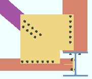
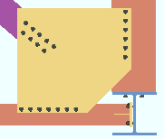
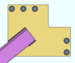
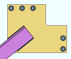
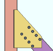
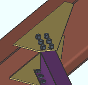
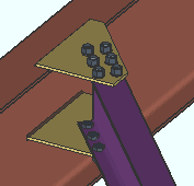
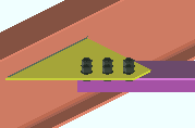
Gusset cut: Automatic or Cope or Clip . This " ![]() Connection specifications " option can apply to a horizontal brace connecting to the top flanges of two beams with an interposed column (illustration below), or to two beams framing to one another at a corner (not illustrated below). The horizontal braces may connect to the top flanges of the beams (illustrated below) or to the webs of the beams (not illustrated).
Connection specifications " option can apply to a horizontal brace connecting to the top flanges of two beams with an interposed column (illustration below), or to two beams framing to one another at a corner (not illustrated below). The horizontal braces may connect to the top flanges of the beams (illustrated below) or to the webs of the beams (not illustrated).
|
|
' Automatic ' instructs connection design to apply a setup choice ( Home > Project Settings > Fabricator > Standard Fabricator Connections > Gusset Plate Settings > " Gusset cut type around column " or " Gusset cut type to beam interface ").
' Cope ' instructs connection design to create the gusset plate with two cuts.
' Clip ' creates the gusset with a single diagonal cut. Where there is an interposed column (as illustrated above), this is likely to result in a larger gusset plate, but an increase in gusset size may not occur where there is no interposed column.
Advanced Selection: GussetCutIsCope
Advanced Selection: GussetCutAuto
Parametric module: GussetCutIsCope
Parametric module: GussetCutAuto
Use OS gusset holes: ![]() or
or ![]() . This "
. This " ![]() Connection specifications " option affects holes in the brace-to-gusset interface only. It does not affect holes in, for example, a gusset-to-clip angle interface.
Connection specifications " option affects holes in the brace-to-gusset interface only. It does not affect holes in, for example, a gusset-to-clip angle interface.
|
If this box is checked (
), oversized round holes are used in the brace-to-gusset interface. Since AISC guidelines require that slip critical bolts be used in such situations, connection design automatically changes the " NM bolt type " to slip critical bolts (for example, to ' A325SC ' bolts).
If the box is not checked (
), the gusset is designed with standard round holes in the brace-to-gusset interface.
Advanced Selection: UseOSGussetHoles
Parametric module: UseOSGussetHoles
Pipe/tube end fitting: Welded or Bolted or Paddle plate or Double paddle plate . This " ![]() Connection specifications " option applies when the horizontal brace's " Section size " is an HSS or pipe or tube.
Connection specifications " option applies when the horizontal brace's " Section size " is an HSS or pipe or tube.
|
|
|
|
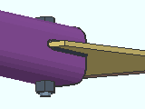
' Welded ' cuts a ' Notch ' in the HSS brace (pipe or tube). The gusset fits into the notch and is field welded to the brace. One, two or zero erection field bolts hold the brace into place for field welding. See : Member Detailing Settings > " Notch length clearance " and " Erection bolts " and Bolt Settings > " HSS welded brace erection bolts ."
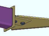
' Bolted ' creates a built-up tee end fitting that shop welds to the HSS brace (pipe or tube) and field bolts to the gusset plate.
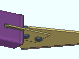
' Paddle plate ' designs a ' Notch ' in the HSS brace (pipe or tube) so that the paddle plate can be fitted into the notch and be shop welded to the brace. The paddle plate bolts to the gusset.
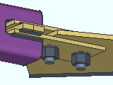
' Double paddle plate ' designs a ' Notch ' in the HSS brace (pipe or tube) so that two paddle plates can be fitted into the notch and bolted to the top and bottom faces of the gusset plate. Spacers that are the thickness of the gusset plate are inserted in the notch between the two paddle plates.
'Bolted' locks: to top flange or web || perpendicular || 2- or 3-point || intersection || corner ||
'Paddle plate' locks: to top flange or web || perpendicular || 2- or 3-point || intersection || corner ||
Spacers locks for double: to top flange or web || perpendicular || 2- or 3-point || intersection || corner |||
Advanced Selection: PipeTubeEndFitting
Parametric module: PipeTubeEndFitting
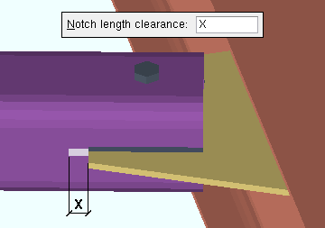
Notch length clearance: The distance (in the primary dimension " Units " or other units ) that you want the notch to extend beyond the gusset plate. This " ![]() Connection specifications " option applies when the horizontal brace's " Section size " is HSS rectangular (tube) or HSS round (pipe) and the " Pipe/tube end fitting " for this end is set to ' Welded '.
Connection specifications " option applies when the horizontal brace's " Section size " is HSS rectangular (tube) or HSS round (pipe) and the " Pipe/tube end fitting " for this end is set to ' Welded '.
|
The " Notch length clearance " (X) for an HSS rectangular horizontal brace field welded to the gusset. |
Advanced Selection: NotchLengthClearance
Parametric module: NotchLengthClearance
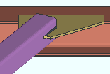
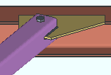
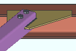
Erection bolts: Automatic or None or One or Two . This " ![]() Connection specifications " option applies when the horizontal brace's " Section size " is HSS rectangular (tube) or HSS round (pipe) and the " Pipe/tube end fitting " for this end is set to ' Welded '.
Connection specifications " option applies when the horizontal brace's " Section size " is HSS rectangular (tube) or HSS round (pipe) and the " Pipe/tube end fitting " for this end is set to ' Welded '.
|
|
|
' Automatic ' instructs connection design to apply a setup choice ( Home > Project Settings > Fabricator > Detailing > Member Detailing Settings > the " Horizontal Braces " section > " HSS erection bolts ").
' None ' configures connection design to not generate an erection bolt or the holes that the bolt goes into.
' One ' creates a field erection bolt along with holes for inserting the bolt into.
' Two ' creates two field erection bolts along with holes for inserting the bolts into.
Member Detailing Settings: " HSS erection bolts " and " Hole type for HSS erection bolts "
Bolt Settings: " HSS welded brace erection bolts "
Advanced Selection: ErectionBolts
Parametric module: ErectionBolts
Angle end fitting: Bolted or Welded . A horizontal brace can be welded to its gusset plate when -- in " ![]() General settings " -- its " Section size " is an angle and its " Side of gusset " is ' Near side ' or ' Far side '.
General settings " -- its " Section size " is an angle and its " Side of gusset " is ' Near side ' or ' Far side '.
|
|
' Bolted ' bolts the angle to the gusset plate.
' Welded ' welds the angle to the gusset plate. The "
Connection specification " options " Include end welds " and " Balanced welds " configure the weld pattern.
Include end welds: Automatic or Yes or No . This applies when " Angle end fitting " is set to ' Welded ' here, in " ![]() Connection specifications ."
Connection specifications ."
|
|
' Automatic ' specifies that connection design apply a setup choice ( Home > Project Settings > Fabricator > Detailing > Member Detailing Settings " > the " Horizontal Braces " section > " Welded angle end weld ").
' Yes ' welds three sides of the angle to the gusset plate. One weld is placed on the end of the angle. The other two welds run along the length of the angle.
' No ' welds two sides of the angle to the gusset plate. Both welds are along the length of the angle.
Balanced welds: Automatic or Yes or No . This applies when " Angle end fitting " is set to ' Welded ' here, in " ![]() Connection specifications ."
Connection specifications ."
|
|
' Automatic ' specifies that connection design apply a setup choice ( Home > Project Settings > Fabricator > Detailing > Member Detailing Settings > the " Horizontal Braces " section > " Welded angle balanced welds ").
' Yes ' instructs connection design to create a weld group that is balanced. A weld group is balanced when its center of resistance aligns with the center of force.
' No ' puts welds of equal length along the length of the brace.
Clip end operation: Automatic or Yes or No . This " ![]() Connection specifications " option can apply to a horizontal brace whose " Section size " is an angle (L) or a W tee (WT). or a wide flange (W).
Connection specifications " option can apply to a horizontal brace whose " Section size " is an angle (L) or a W tee (WT). or a wide flange (W).
|
|
|||||||
|
|||||||
|
' Automatic ' specifies that connection design apply the choice made for horizontal braces to " Clip end operation on angle brace gusset plates " or " Clip end operation on W tee brace gusset plates " or " Clip end operation on Wflg brace gusset plate " at Home > Project Settings > Fabricator > Standard Fabricator Connections > Gusset Plate Settings .
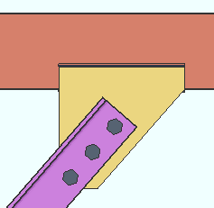
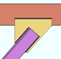
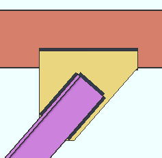
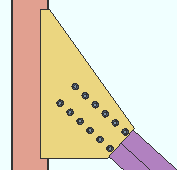
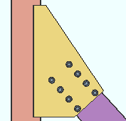
' Yes ' instructs connection design to perform a ' Clip ' operation on the gusset plate to create an edge perpendicular to the vertical brace. You will get a set of connection design locks in a leaf named as shown in one of the tables below.
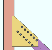
' No ' configures connection design to not perform the ' Clip ' operation, and the gusset comes to a point over the vertical brace. You will get a set of connection design locks in a leaf named as shown in one of the tables below.
You get different connection design locks, depending on the choice made here:
Connection Design Locks for Single Angle Horizontal Braces ' Yes ' ' No ' to bm flange Gusset One Member Gusset One Member Square to bm web Gusset One Member Gusset One Member Square bm-bm corner Gusset To Two Beams Gusset To Two Beams Square bm-col-bm corner Gusset To Two Beams Gusset To Two Beams Square shared gusset Gusset 2 Point Gusset 2 Point Square
for Tee, Wide Flange and Double Angle ' Yes ' ' No ' to bm flange Gusset One Member Gusset One Member Square to bm web Gusset One Member Gusset One Member Square bm-bm corner Gusset To Two Beams Gusset To Two Beams Square bm-col-bm corner Gusset To Two Beams Gusset To Two Beams Square shared gusset Gusset 2 Point Gusset 2 Point Square End connection failure message: Shared brace Clip end-operatiion settings must match
Gusset to beam connection: Automatic or Welded or Clip angle . This " ![]() Connection specifications " option applies to most horizontal brace framing situations to a beam web.
Connection specifications " option applies to most horizontal brace framing situations to a beam web.
|
|
' Automatic ' specifies that connection design apply a setup choice ( Home > Project Settings > Fabricator > Member Detailing Settings > the " Horizontal Braces " section > " Gusset to single beam connection ").
' Welded ' instructs connection design to shop weld the horizontal brace gusset plate to the supporting beam. Gussets to the webs of two beams are always designed with clip angles, even when ' Welded ' is selected. For a gusset to the web of two beams, you will get the following connection changed message when ' Welded ' is selected:
Conn changed. Possibly: Gusset welded vs Gusset clip angle ' Clip angle ' attaches the gusset to the beam with a clip angle. The " Beam to clip connection " may be ' Welded ' or ' Bolted '. " Gusset clips on " (' Both sides ' or ' Near side ' or ' Far side ') is another connection specification option that affects how the gusset clips are designed. Connection design can design clip angles for 2-point horizontal braces, but not 3-point.
Advanced Selection: GussetToBeamConnectionIndex
Parametric module: GussetToBeamConnectionIndex
Connection design locks: NS/FS Clip Conn2 (gusset clip angle(s) bolted or welded to beam web)
Connection design locks: NS/FS Clip Conn2 (gusset clip angle(s) perp to beam web)
Connection design locks: NS/FS Clip Conn2 (gusset clip angle(s) for 2-point bracing)
Gusset to clip connection: Automatic or Welded or Bolted . This " ![]() Connection specifications " option sets the method of attachment for the gusset-to-clip-angle interface that connection design applies when " Gusset to beam connection " is set to ' Clip angle '.
Connection specifications " option sets the method of attachment for the gusset-to-clip-angle interface that connection design applies when " Gusset to beam connection " is set to ' Clip angle '.
|
||
| For a gusset to two beams, the gusset-to-brace connection is shop bolted , and the clip-to-beam connection is field bolted. The gusset-to-clip connection is ' Welded ' or ' Bolted ' per the choice made here. |
' Automatic ' specifies that connection design apply a setup choice ( Home > Project Settings > Fabricator > Member Detailing Settings > the " Horizontal Braces " section > " Gusset to clip connection ").
' Welded ' shop welds the clip angle(s) to the gusset plate. The " Attach clip to " option needs to be set to ' On gusset ' (or possibly, ' Automatic ') to prevent connection design from generating the failure message " Brace clip angle cannot be welded to gusset and shipped with beam ." Attempting to specify a welded-welded gusset clip angle will get you the fail message: " Brace clip angle cannot be welded to both beam and gusset ."
' Bolted ' instructs connection design to bolt the clip angle(s) to the gusset plate. Clip angles at a beam-beam corner (as shown above) and for 2-point bracing will be shop bolted to the gusset. For clip angles to a single beam, the choice made to " Attach clip to " sets whether the bolts at the gusset-to-clip interface are shop bolts or field bolts.
Advanced Selection: GussetToClipConnection
Parametric module: GussetToClipConnection
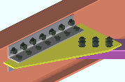
Beam to clip connection: Automatic or Welded or Bolted . ' Welded ' always specifies a shop weld. ' Bolted ' may specify shop bolting or field bolting depending on other settings. The choice made here applies when the " Gusset to beam connection " is ' Clip angle '.
|
||||||
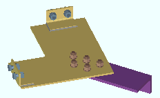
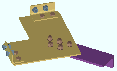
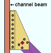
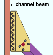
| For both examples, " Attach clip to " and " Attach gusset to " were set to ' On supporting ', which makes the clip-angle-and-gusset assembly shop attach to the beam. The clip angle shop welds or shop bolts to the back of the channel beam. The gusset field bolts to the brace. |
' Automatic ' specifies that connection design apply a setup choice ( Home > Project Settings > Fabricator > Member Detailing Settings > the " Horizontal Braces: Clip angle of gusset " section > " Beam to clip connection ").
' Welded ' instructs connection design to shop weld the horizontal brace gusset clip to the supporting beam. The " Attach clip to " option should be set to ' On supporting ' (or possibly, ' Automatic ') if you don't want connection design to generate the failure message " Brace clip angle cannot be welded to beam and shipped with gusset ." Also, attempting to shop weld the clip angle to a wide flange beam can produce the following failure message: " Brace clip angle connecting to single wflg beam cannot be welded ." Attempting to specify a welded-welded gusset clip angle will get you the fail message: " Brace clip angle cannot be welded to both beam and gusset ."
' Bolted ' instructs connection design to bolt the horizontal brace gusset clip to the web of the supporting beam. The gusset-to-clip-connection bolts are shop bolts when " Attach clip to " is set to ' On supporting ', field bolts when " Attach clip to " is set to ' On gusset '.
Attach clip to: Automatic or On gusset or On supporting . This option applies when the " Gusset to beam connection " is ' Clip angle '.
|
||||||
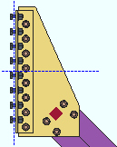
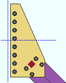
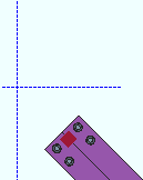
| In both of these examples, " Attach gusset to " is set to ' On brace '. The beam in these screen shots is hidden (displayed in ' Stick ' with Display Options > Member lines turned off). |
' Automatic ' specifies that connection design apply a setup choice ( Home > Project Settings > Fabricator > Member Detailing Settings > the " Horizontal Braces: Clip angle of gusset " section > " Attach clip to ").
' On gusset ' specifies that the gusset clip angle(s) shop bolt or shop weld to the gusset plate. If " Attach gusset to " is ' On supporting ', the clip angles and the gusset are shipped with the beam. If " Attach gusset to " is ' On brace ' (as in the above, left example), the clip angles and gusset are shipped with the brace.
' On supporting ' specifies that the gusset clip angle(s) shop bolt or shop weld to the beam. The clip angle will be shipped with the beam and detailed on the beam. Clip angles must be shop welded to an HSS/TS beam and can optionally be shop welded to a channel beam. If " Attach gusset to " is also set to ' On supporting ', the entire clip-angle-and-gusset assembly is shipped with the beam. If " Attach gusset to " is set to ' On brace ' (as in the above, right example), only the clip angle -- not the gusset -- is shipped with the beam.
End connection failure message: Brace clip angle must be welded to and shipped with hss beam
Attach gusset to: Automatic or On brace or On supporting . This applies when the " Gusset to beam connection " is ' Clip angle '. When " Gusset to beam connection " is ' Welded ', the gusset shop welds directly to the supporting beam, field bolts to the brace, and this option is ignored.
|
||||||
| In both of these examples, " Attach clip to " is set to ' On brace '. The beam in these screen shots is hidden (displayed in ' Stick ' with Display Options > Member lines turned off). |
' Automatic ' specifies that connection design apply a setup choice ( Home > Project Settings > Fabricator > Member Detailing Settings > the " Horizontal Braces: Clip angle of gusset " section > " Attach gusset to ").
' On brace ' specifies that the gusset shop bolt to the brace. The gusset plate will be shown on the horizontal brace detail. Gusset clip angles may or may not be shop attached to (and shipped with) the gusset plate depending on the choice made to " Attach clip to ."
' On supporting ' specifies that the entire gusset-plate-and-clip-angle assembly be shop attached to and shipped with the beam and shown on the beam detail. The clip angle may shop bolt or shop weld to the beam. Clip angles can be shop welded to an HSS/TS or channel beam. Clip angles cannot be shop bolted to an HSS/TS beam.
End connection failure message: Brace clip angle must be welded to and shipped with hss beam
Gusset clips on: ![]() Auto or Both sides or Near side or Far side . This "
Auto or Both sides or Near side or Far side . This " ![]() Connection specifications " option applies when the " Gusset to beam connection " is ' Clip angle ' or, possibly, ' Automatic '.
Connection specifications " option applies when the " Gusset to beam connection " is ' Clip angle ' or, possibly, ' Automatic '.
| ' |
|
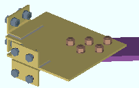
' Both sides ' attaches clip angles to both sides of the gusset plate if there is no material interference. If the supporting beam's flange interferes, connection design creates angles on only one side. |
|
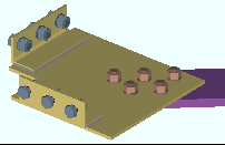
' Near side ' instructs connection design to try to place the clip angles on the near side of the gusset. If the angles clash with the beam, connection design moves them to the far side instead of failing the connection. |
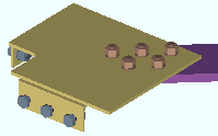
|
' Far side ' instructs connection design to try to place the clip angles on the far side of the gusset. If the angles clash with the beam, connection design moves them to the near side instead of failing the connection. |
Advanced Selection: GussetClipsOnAuto
Advanced Selection: GussetClipsOn
Parametric module: GussetClipsOnAuto
Parametric module: GussetClipsOn
Clip angle size: ![]() Auto or the section size of the angle material to be used for the clip angle (near side or far side) or clip angles (both near side and far side) that attach the gusset plate to a beam web or to two beam webs (at a beam-beam corner or beam-column-beam corner).
Auto or the section size of the angle material to be used for the clip angle (near side or far side) or clip angles (both near side and far side) that attach the gusset plate to a beam web or to two beam webs (at a beam-beam corner or beam-column-beam corner).
'
Auto (checked) ' instructs connection design to apply a setup choice ( Home > Project Settings > Fabricator > Member Detailing Settings > the " Horizontal Braces " section > " Clip angle size ").
'
Auto (not checked)' lets you enter the section size. If the section you enter does not exist in the local shape file, validation will require that you to make a different entry. To enter an angle, you can type in the section size that you want (e.g., ' L4x3x5/16 '), or you can press the "file cabinet" browse button (
) and double-click any section that is on the list of available angles in the local shape file .
Advanced Selection: ClipAngleSizeAuto
Advanced Selection: ClipAngleSizeIndex
Parametric module: ClipAngleSizeAuto
Parametric module: ClipAngleSizeIndex
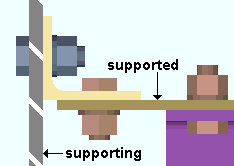
Attach long leg to: Automatic or Supported or Supporting .
|
The supported is the gusset plate. The supporting is the web of the beam. |
' Automatic ' specifies that connection design apply a setup choice ( Home > Project Settings > Fabricator > Member Detailing Settings > the " Horizontal Braces " section > " Attach long leg to ").
' Supported ' instructs connection design to attach the long leg of the angle to the gusset plate.
' Supporting ' attaches the long leg of the angle to the beam.
Advanced Selection: AttachLongLegTo
Parametric module: AttachLongLegTo
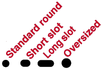
Hole type supported: ![]() Auto or Standard round or Short slot or Oversized or Long slot or User slot #1 or User slot #2 . The hole type selected here, together with the "
Auto or Standard round or Short slot or Oversized or Long slot or User slot #1 or User slot #2 . The hole type selected here, together with the " ![]() Connection specifications " option " Bolt diameter ," set the diameter of holes for shop bolting the clip angle to the gusset plate.
Connection specifications " option " Bolt diameter ," set the diameter of holes for shop bolting the clip angle to the gusset plate.
'
Auto (checked) ' instructs connection design to apply a setup choice ( Home > Project Settings > Fabricator > Member Detailing Settings > " Horizontal Braces " section > " Hole type supported ").
'
Auto (not checked) ' lets you select any of the above-listed hole types from the menu (
).
Advanced Selection: HoleTypeSupportedAuto
Advanced Selection: HoleTypeSupported
Parametric module: HoleTypeSupportedAuto
Parametric module: HoleTypeSupported
Hole type supporting: ![]() Auto or Standard round or Short slot or Oversized or Long slot or User slot #1 or User slot #2 . The hole type selected here, together with the "
Auto or Standard round or Short slot or Oversized or Long slot or User slot #1 or User slot #2 . The hole type selected here, together with the " ![]() Connection specifications " option " Bolt diameter ," set the diameter of holes for field bolting the outstanding leg of the clip angle to the beam.
Connection specifications " option " Bolt diameter ," set the diameter of holes for field bolting the outstanding leg of the clip angle to the beam.

'
Auto (checked) ' instructs connection design to apply a setup choice ( Home > Project Settings > Fabricator > Member Detailing Settings > " Horizontal Braces " section > " Hole type supporting ").
'
Auto (not checked) ' lets you select any of the above-listed hole types from the list box (
).
Advanced Selection: HoleTypeSupportingAuto
Advanced Selection: HoleTypeSupporting
Parametric module: HoleTypeSupportingAuto
Parametric module: HoleTypeSupporting
Bolt type: ![]() Auto or
Auto or ![]() Auto . This "
Auto . This " ![]() Connection specifications " option sets the bolt type in both legs of the clip angle that fastens the horizontal brace gusset to the beam web.
Connection specifications " option sets the bolt type in both legs of the clip angle that fastens the horizontal brace gusset to the beam web.
'
Auto (checked) ' instructs connection design to apply a setup choice ( Home > Project Settings > Job > Bolt Settings > the " Horizontal brace gusset to supporting " section > " Bolt type ").
'
Auto (not checked) ' lets you select a bolt type from the list box (
). Choices in the list box come from Home > Project Settings > Job > Bolt Settings .
Bolt diameter: ![]() Auto or
Auto or ![]() Auto . This sets the diameter of bolts in both legs of the clip angle that fastens the horizontal brace gusset to the beam web. The bolt diameter entered here, together with the "
Auto . This sets the diameter of bolts in both legs of the clip angle that fastens the horizontal brace gusset to the beam web. The bolt diameter entered here, together with the " ![]() Connection specifications " option " Hole type supported " or " Hole type supporting " set the diameter of holes the bolts go into.
Connection specifications " option " Hole type supported " or " Hole type supporting " set the diameter of holes the bolts go into.
| diameter |
|
'
Auto (checked) ' instructs connection design to apply a setup choice ( Home > Project Settings > Job > Bolt Settings > the " Horizontal brace gusset to supporting " section > " Bolt diameter ").
'
Auto (not checked) ' lets you either type in any diameter (inches or mm), or select a bolt diameter from the combo box (
). The diameters that are listed in the combo box come from Home > Project Settings > Job > Bolt Settings > the " Available bolt diameters " list.
Setup options tied to bolt diameter: " Vertical edge distance at ends " ( Home > Project Settings > Fabricator > Standard Fabricator Connections > Clip Angle Settings ), " Allow reduced edge distance for 7/8" and 1" bolts " ( Home > Project Settings > Fabricator > Detailing > Member Detailing Settings > " Horizontal Braces " section).
Advanced Selection: BoltDiameterAuto
Advanced Selection: BoltDiameter
Parametric module: BoltDiameterAuto
Parametric module: BoltDiameter
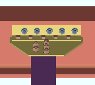
Stagger bolts: Automatic or Yes or No . This " ![]() Connection specifications " option applies to the " Clip angle size " selected above if the clip angle is bolted to the gusset.
Connection specifications " option applies to the " Clip angle size " selected above if the clip angle is bolted to the gusset.
' Yes '
 |
' No '
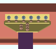 |
' Automatic ' specifies that connection design apply a setup choice ( Home > Project Settings > Fabricator > Member Detailing Settings > the " Horizontal Braces " section > " Stagger bolts ").
' Yes ' instructs connection design to attempt to stagger the bolts on the clip angle(s).
' No ' configures connection design to not stagger the bolts.
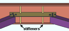
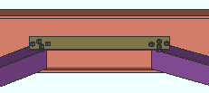
Check supporting member web stress: If required or Never . This " ![]() Connection specifications " option applies to a single horizontal brace gusset or 2 point or 3 point horizontal brace gusset plate that is welded to a beam web when there is no member framing to the opposite side of the web. For such a framing situation, the " Supporting member web stress " is reported as a " Left/Right end limit state ." This option controls whether or not the supporting member web stress is checked by connection design when it creates the horizontal brace gusset plate.
Connection specifications " option applies to a single horizontal brace gusset or 2 point or 3 point horizontal brace gusset plate that is welded to a beam web when there is no member framing to the opposite side of the web. For such a framing situation, the " Supporting member web stress " is reported as a " Left/Right end limit state ." This option controls whether or not the supporting member web stress is checked by connection design when it creates the horizontal brace gusset plate.
|
|
||
| Connection design may add beam web stiffeners when ' If required ' is selected. A 2-point gusset is shown. This also applies to 3-point gussets and single horizontal brace gussets. |
' If required ' results in connection design calculations 175 and 185 and 359 being potential causes of connection failure. To prevent such a failure, beam web stiffeners may be designed. The " Maximum web stiffener thickness " for these stiffeners can be set in Home > Project Settings > Fabricator > Detailing > Member Detailing Settings > the " Horizontal Braces " section. The stiffeners can be designed for 2-point, 3-point or single horizontal brace gusset plates.
' Never ' results in calculations 175 and 185 and 359 still being performed, if applicable, but not ever causing the connection to fail. In the Connection Design Calculations or Expanded Connection Design Calculations , the results of the check will be reported with a parenthetical, for-information-only note such as " (For information only, brace force that produces local beam web stress of .9Fy (185) 8.9 kips ) ." Stiffeners are not designed when ' Never ' is selected.
End connection failure message: Supporting web/flg overstressed by axial load .
Connection Guide: Horizontal Brace Gusset with Beam Web Stiffeners
