"  Seated Plate " connection design locks
| " |
|
|||
"  |
|
||
Connection Guide: Click here and here for related screen shots.
User Defined Connections: Settings that are locked (
) in the user defined connection file will automatically be locked on the member edit window. You can, if you so choose, manually lock additional settings on the member edit window, and your changes will be retained, through multiple processes, so long as you do not change to a different connection then switch back to the original user defined connection.
Joist Edit: To change a setting, first set it to locked (
). Related settings that are unlocked (
) may be updated, and the "
Left/Right end limit state " calculations will be updated. Settings that are locked (
) will not be changed by connection design , even if doing so might prevent a connection failure.
Connection design locks :
| Note: Locks not shown on the drawing are marked ( not depicted ). |
![]() Seated Plate
Seated Plate
Seat plate
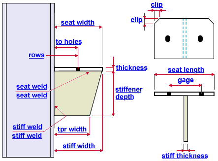
Length ( seat length ): The distance from the near side edge of the seat plate to the far side edge of the seat plate (see example ). The seat plate bolts to the top chord of the supported joist. Its length should be wider than the joist bearing width in Shapes Properties .
End connection failure message: Seat length less than minimum required
Width ( seat width ): The distance from the edge of the seat plate that welds to the supporting member to the opposite edge of the seat plate (see example ) The seat plate bolts to the top chord of the supported joist. Its width must be long enough to allow the minimum bearing entered in Shapes Properties for the supported joist.
End connection failure message: Joist bearing shoe slot edge distance less than setup minimum
End connection failure message: Supporting surface is shorter than minimum joist bearing length
End connection failure message: Seat width less than minimum requiredPlate thickness ( thickness ): The " Material thickness " of the seat plate -- see example . The seat plate bolts to the top chord of the supported joist.
Corner clip ( clip ): Corner clips are 45 degree cuts at the two corners of the seat plate edge that frames to the supporting member. You may, for example, want to specify corner clips when the joist seat frames to a wide flange column web in order to prevent material clashes between the corners of the plate and the web fillets. A specific distance places the beginning of the corner clip that distance from the corner. ' 0 ' results is square corners (no corner clip).
Bolts in seat plate
Diameter ( not depicted ): The bolt diameter. You can either type in any diameter (inches or mm), or you can select a bolt diameter from the combo box (
). The diameters that are listed in the combo box come from Home > Project Settings > Job > Bolt Settings > the " Available bolts " list. The bolt diameter entered here, together with the " Hole type ," set the diameter of holes that field bolt the seat plate to the top chord of the supported joist.
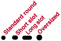
Hole type ( not depicted ): Standard round or Short slot or Oversized or Long slot or User slot #1 or User slot #2 . The hole type selected here, together with the " Bolt diameter " entered below, set the hole diameter for field bolting the seat to the top chord of the joist.

Rows: The number of bolt rows ( 0 or 1 or 2 or 3 ) for field bolting the seat plate to the joist. ' 0 ' prevents holes from being designed in the seat plate, presumably because you want the seat to field weld to the joist. ' 1 ' row is shown in the example . If ' 2 ' or ' 3 ' rows are entered, the bolt " Bolt spacing " that is set for the bolt diameter, in Connection Detailing/Fabricator Options , is applied as the row spacing.
Horizontal to holes ( to holes ): The distance from the end of the joist to the center of the first row of holes in the seat plate (see example ). The end of the joist is not shown in the model. To calculate where the end of the joist is positioned, you need to subtract the " Setback " (" Field clearance " or " Input minus dimension " or " Automatic minus dimension ") for that end of the joist.
Gage: The distance (center to center) between the two columns of holes in the seat plate. These holes are used for field bolting the angle seat to the top chord of the supported joist -- see example .
Stiffener plate
Depth ( stiffener depth ): The distance between the top and bottom edges of the stiffener plate (see example ). The stiffener shop welds to the supporting member and the seat plate.
End connection failure message: Seated connection weld fails in shear
Width ( stiff width ): The length of the top edge of the stiffener plate (see example ).
Plate thickness ( stiff thickness ): The " Material thickness " of the stiffener plate -- see example .
End connection failure message: Seated connection stiffener fails in buckling
Taper width ( tpr width ): The length of the bottom edge of the stiffener plate. If the " Taper width ".is less than the " Width " (as in the example ), then the stiffener plate is tapered.
Clip ( not depicted ): The vertical distance from the corner of the stiffener plate (before it is cut) to where you want the 45 degree cut to begin. Enter ' 0 ' if you do not want the corner clipped.
Welds
Seat ( seat weld ): The weld size for shop welding the stiffener plate to the seat plate (see example ).
Stiffener ( stiff weld ): The weld size for shop welding the edge of the seat plate and stiffener to the web/flange of the column (see example ).


