Connection Guide : Joist Connections
| Disclaimer: This guide is not comprehensive. It shows only a few of the many joist connections that connection design can create. |
Also see :
- Joist connection design locks ( Joist Edit window / User Defined Connections setup window)
- Auto Cap Plate Supporting a Joist (connection guide)
- Joist Edit (window for applying/reviewing Joist specs)
- Joist Connection Settings (setup for joist connections)
- Bolt Settings (bolt setup for joist connections)
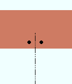
| Joist Top Chord Bolted to a Beam Flange | |
| Input connection type: ' Bearing '
|
|
| Settings: ' Bolted ' top chord to support. " NM bolt diameter " sets the hole size. " Gage " comes from the local shape file . | |
| Comments: The " Input elevation " of the joist must be the beam's top flange elevation. | |
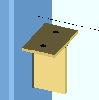
| Plate Seat for the Top Chord of a Joist | |
| Connection Design Locks = " Seated Plate " | |
|
Input connection type: ' Seated joist '. |
| Settings: ' Plate ' material. " Gage " comes from the local shape file . " NM bolt diameter " sets the hole size. Seat is " Bearing depth " below the workline of the joist. | |
| Comments: The seat is a built-up tee made of welded plates. | |
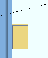
| Plate Seat for the Top Chord of a Sloping Joist | |
| Connection Design Locks = " Seated Plate " | |
| Input connection type: ' Seated joist '
|
|
|
Settings: ' Plate ' seat material. " Gage " comes from the local shape file . " NM bolt diameter " sets the hole size. Seat is " Bearing depth " distance below the workline of the joist. |
|
| Comments: Unlike plate seats for beams, the supporting surface of a plate seat for a sloping joist is flat. | |
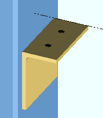
| Angle Seat for the Top Chord of a Joist | |
| Connection Design Locks = " Seated Angle " | |
|
Input connection type: ' Seated joist '. |
| Settings: ' Unstiffened L ' seat material. " Gage " comes from the local shape file . " NM bolt diameter " sets the hole size. Seat is " Bearing depth " distance below the workline of the joist. | |
| Comments: Angles must be listed in Home > Project Settings > Fabricator > Standard Fabricator Connections > Preferred Angle Sizes , or connection design will instead create a seat made of plate material. | |
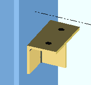
| Stiffened Angle Seat for a Joist Top Chord | |
| Connection Design Locks = " Seated Angle " | |
| Input connection type: ' Seated joist '.
|
|
| Settings: ' Unstiffened L ' seat material. " NM bolt diameter " sets hole diameter. " Gage " and " Bearing depth " come from local shape file . | |
| Comments: Angles must be listed in Home > Project Settings > Fabricator > Standard Fabricator Connections > Preferred Angle Sizes . | |
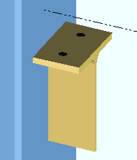
| W Tee Seat for a Joist Top Chord | |
| Connection Design Locks = " Seated Tee " | |
|
Input connection type: ' Seated joist '. |
| Settings: ' Tees ' seat material, " NM bolt diameter " sets hole diameter. " Gage " and " Bearing depth " come from local shape file . | |
| Tee sections must be listed in Home > Project Settings > Fabricator > Standard Fabricator Connections > Preferred WT Sizes . If connection design cannot find an appropriate tee in the setup list, a seat made of plate material is designed. | |
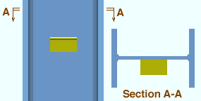
| Stability Angle for a Joist's Bottom Chord Extension | |
| Connection Design Locks = " Joist Stabilizer Angle " | |
|
Settings: " Extend bottom chord " (checked) ' Angle ' stabilizing material.
|
|
| Comments: Connection design initially uses the Home > Project Settings > Fabricator > Standard Fabricator Connections > Joist Connection Settings > " Bottom chord extension seat angle ." | |
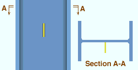
| Stability Plate for a Joist's Bottom Chord Extension | |
| Connection Design Locks = " Joist Stabilizer Plate " | |
|
Settings: " Extend bottom chord " (checked), ' Plate ' stabilizing material.
|
| Comments: Connection design initially uses the Home > Project Settings > Fabricator > Standard Fabricator Connections > Joist Connection Settings > " Bottom chord extension plate ." | |
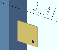
|
Per an OSHA standard, the bottom chord stability plate should include an erection hole. Under " |
| Joist Top Chord to Concrete Wall with Pocket & Bearing Embed | |
| Connection Design Locks = " Joist End Pocket "
(embeds are custom members, not system connections) |
|
| Input connection type: ' Bearing ' or ' Auto standard ' or ' User defined '.
|
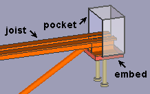
|
| Settings: " Schedule entry " (top chord) | |
| Comments: The joist frames to a concrete wall (or tilt-up panel if you have a concrete license ). The " Pocket grout thickness " in this example is ' 0 ' (zero), a value which places the embed flush with the bottom of the shoe. The embed shown is a plate, but could have been an angle or channel. | |
| Top Chord Joist Seat to an Embed Plate | |
| Connection Design Locks = see plate seat or etc.
(embeds are custom members, not system connections) |
|
| Input connection type: ' Seated ' or ' Auto standard ' or ' User defined '.
|
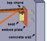
|
| Settings: The " Schedule entry " (top chord) may be a plate (shown) or angle or channel. | |
| Comments: An embed created by a top chord " Schedule entry " is a custom member , not a system connection. The system connection in this example is the joist seat. | |
| Extended Joist Bottom Chord to an Embed Plate | |
| Connection Design Locks = see stabilizer or etc.
(embeds are custom members, not system connections) |
|
| Input connection type: Any except ' Plain end '.
|
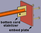
|
| Settings: " Schedule entry " (bottom chord). " |
|
| Comments: The embed is, by default, positioned 1 inch above the stabilizer. You can change this " Support offset " on the Embed Plate window. | |


