The Joist Edit window (or Joist Edit - Multiple or Joist Review )
- To open this window.
- If you are editing one joist, its member number (" Member xx ") is printed in the title bar, and the "
 Summary " lists other joists that have been assigned the same piecemark.
- " Joist Edit - Multiple Members " is this window's title if you are editing multiple joists .
- This window is mostly read-only and called Joist Review if the " Model complete date " is set and ' Restrictive ' is selected.
-
 " Copy " " Paste " " Save " " Load " buttons (form buttons) are embedded in the headers for individual leaves on this window. They apply to the settings that are contained in that leaf. Some form buttons, such as those for [ Left end settings ] apply to multiple leaves. Click here (
  ) for more information. " Paste " and " Load " replace mixed entries to a single field with a single entry. " Copy " and " Save " ignore fields with mixed entries, treating them as if they have no entry or do not exist. Form buttons above sections that have multiple subordinate leaves under them -- e.g., [ Left end settings ] or [ Right end settings ] -- operate on settings under all of the subordinate leaves. For example, if you wanted to copy a connection from the left end to the right end, you would use the " Copy " button under [ Left end settings ], then use the " Paste " button under [ Right end settings ]. Special case: Form buttons do not operate on " Piecemark ."
- " Save " (
 ) places a file (which you name) in a subfolder of the
  form/joist folder that is used by your current version of this program. The exact subfolder depends on where the button is located. " Load " (
  ) takes you to that same folder.
|
|||||
|
|
||||
Section size: This joist's main material .
To enter a section size: You can type in the section size that you want, or you can press the "file cabinet" browse button (
) and double-click any section that is on the list of available joist materials in the local shape file . If you enter a section size that is not available , validation brings up a yes-no dialog with the warning, " The section size is not available from suppliers. Are you sure you want to use it? " Entering a material other than joist material will result in the end connection failure message " Invalid material type for this member ."
Joist manufacturer Section in the local shape file that populates the " Section size " selection list that opens when you press the Default Joist: Default Canam Joist: Canam Vulcraft Joist: Vulcraft You are permitted to enter a joist size that is listed in the local shape file for the " Joist manufacturer " (' Default ' or ' Canam ' or ' Vulcraft ') that is selected in Project Settings . Changing the " Joist manufacturer " will result in all non model complete joists that reside in the model being marked for processing.
To add/edit section sizes: Shapes Properties .
Required file for editing: The " Shape file " path must be set to the local shape file (press " Local ").
To copy section sizes from another shape file: Copy Shapes .Status Display: Member status > Member section size
Report Writer: Member.MaterialFile.SectionSize
Advanced Selection: m.SectionSize
Parametricmodule: m.SectionSize
Piecemark or System piecemark or User piecemark or Frozen piecemark:
Sequence :
Note this scenario: You change the sequence and other settings on this joist, which shares its piecemark with other joists. If you press " Yes " when prompted " Do you want to change all... ," the changed sequence will apply to this joist only, but the other settings will be applied to ALL joists with the same piecemark.
Swap member ends : ![]() or
or ![]() .
.
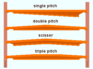
Shape : Parallel or Single pitch or Double pitch or Arched chord or Bowstring or Scissor or Triple pitch or BIM custom .
|
|
' Parallel ' makes the top and bottom chords of the joist parallel with one another.
' Single pitch ' angles the bottom chord with respect to a horizontal top chord.
' Double pitch ' divides the top chord of the joist into two sections, each of which slope to a peak at or near the joist's center. The " Peak offset " sets the distance of the peak from the left end of the joist. The bottom chord is straight.
' Arched chord ' arches both the top and bottom chords of the joist. The " Top chord radius " sets the curvature of the top cord, which in turn sets the curvature of the bottom chord so that the same distance of separation is maintained between all corresponding points along the two chords. .
' Bowstring ' arches the top chord of the joist while the bottom chord stays straight. The " Top chord radius " sets the curvature of the top cord.
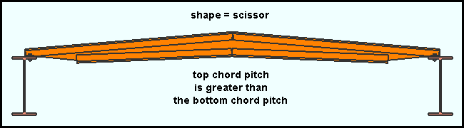
' Scissor ' makes both the top chord and the bottom chord of the joist come to a peak. The " Peak offset " sets the distance of that peak from the left end of the joist.
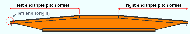
' Triple pitch ' divides the top chord into three different sections, each with a different pitch. The center section of the top chord is parallel with the bottom chord. The bottom chord is straight. The two outside sections of the top chord slope upward toward the center sect on.
' BIM custom ' is a shape that is provided by the " Joist manufacturer " that is selected at Home > Project Settings > Job > Joist Manufacturers . If a custom shape is not provided, a parallel joist shape will be generated.
Peak offset : The distance parallel with the joist's input work points (in the primary dimension " Units " or other units ) from the left end of the joist to the peak of the joist.
|
|
|
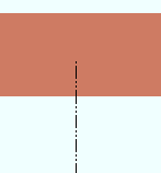
The " Peak offset " option is enabled ( not grayed out ) when ' Double pitch ' or ' Scissor ' is selected as the " Shape ." The joist shown here is a scissor joist. The left end of the joist is identified by an origin reference point symbol ( |
For a ' Double pitch ' joist, the " Peak offset " positions the peak at the top chord. For a ' Scissor ' joist, as is shown in the example above, " Peak offset " positions the peaks at both the top and bottom chords.
Top chord radius : The distance (in the primary dimension " Units " or other units ) that any and all points on the top of the joist's top chord are from the center of a circle that circumscribes the top of the joist's top chord.
|
r = top chord radius. If you were to extrapolate a circle from the curvature of the joist's top chord, the distance from any point on that curve to the center of the circle is the distance entered here. |
The " Top chord radius " option is enabled ( not grayed out ) when ' Arched chord ' or ' Bowstring ' is selected as the " Shape ."
Joist rotation : A positive (+) or negative (-) number of degrees.
|
The axis of rotation is a line through the input points of the joist, which are marked with an X . The " Input elevation " does not change when you rotate the joist. As shown in this example, the left-end top chord reference symbol ( |
' 0 ' degrees orients the joist vertically, that is, so that it its web panel is vertical.
' A positive number ' of degrees rotates the joist clockwise from its zero position.
' A negative number ' of degrees rotates the joist counterclockwise from its zero position.
Panel display method : Automatic or Reserved or Mfg pre-config or User pre-config . The choice that is made here does not affect the joist's ability to connect to other members. The " Panel display method " only affects the appearance of the joist, not its functionality. With the exception of system connection materials, joist materials are dummy materials .
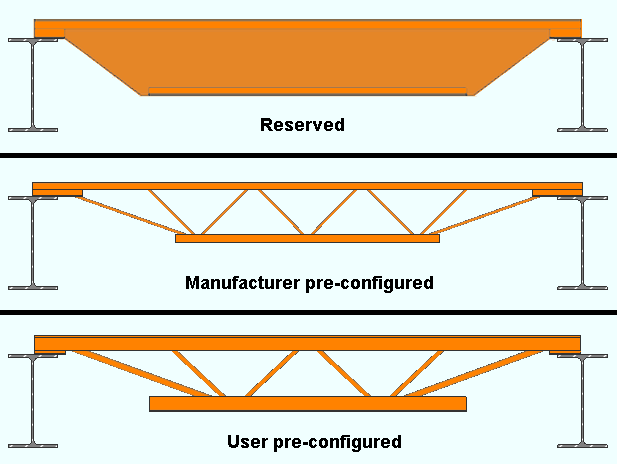
' Automatic ' applies the choice made to " Panel display method " at Home > Project Settings > Job > Joist Manufacturers .
' Reserved ' puts a flat plate layout as a placeholder at the approximate location where web material can be designed by a manufacturer.
' Mfg pre-config ' requires that the " Joist manufacturer " has provided BIM information for the joist. If the manufacturer has not provided such information, you get a warning -- after you press "OK" -- and the joist is displayed as if you had selected ' Reserved '.
VIDEO 
The " Panel display method " is set to ' Mfg pre-config ', but since the manufacturer has not provided valid panel configuration, the user gets a warning. ' User pre-config ' provides an approximation of the joist panel. " User preconfigured panel " options on this window can be used to fine tune the appearance of this joist.
VIDEO The " Panel display method " is set to ' User configured panel ' and settings under " User preconfigured panel " are adjusted. The result is shown in the model.
------------------
Main material : ![]() or
or ![]() .
.
Marked for processing : ![]() or
or ![]() .
.
Marked for detailing : ![]() or
or ![]() . This "
. This " ![]() General settings " button reads
General settings " button reads ![]() by default since joists cannot be detailed.
by default since joists cannot be detailed.
Node-match job : ![]() or
or ![]() . ( read-only )
. ( read-only )
Model complete : ![]() or
or ![]() . ( read-only )
. ( read-only )
Model complete date : **NOT SET** or a month day year .
------------------
WP to WP length, plan: read-only . The work point-to-work point distance (in the primary dimension " Units ") spanned by this joist's member line in a plan view, ignoring elevation. This " ![]() General settings " distance is calculated from the X and Y (but not Z) global coordinates of the joist's input points .
General settings " distance is calculated from the X and Y (but not Z) global coordinates of the joist's input points .
Report Writer: Member.WorkpointToWorkpointLevel
Advanced Selection: m.WorkpointToWorkpointLevel
Parametric module: m.WorkpointToWorkpointLevel
WP to WP length, actual: Read-only . The actual length of this joist's member line (in the primary dimension " Units "). This " ![]() General settings " distance is calculated from the X and Y and Z global coordinates of the joist's input points .
General settings " distance is calculated from the X and Y and Z global coordinates of the joist's input points .
Note: This distance minus any " Setbacks " that have been applied is the actual length of the joist.
Tip: Using Move/Stretch Members or Move/Stretch Members, Include Material to lengthen or shorten a joist or changing a joist's " Input elevation " causes a different distance to be reported here.
Report Writer: Member.WorkpointToWorkpointSlope
Advanced Selection: m.WorkpointToWorkpointSlope
Parametric module: m.WorkpointToWorkpointSlope
Lift assignment : not assigned or a crane placement name . (read-only)
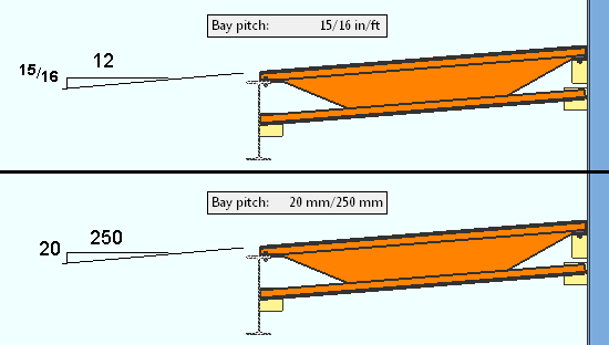
Bay pitch : Read only . This " ![]() General settings " information reports the rise/run of the joist. The pitch is calculated by taking the difference between the joist's left- and right-end " Top of joist " elevation then dividing that difference by the " WP to WP length, actual ." If you are using imperial " Units ," the " Bay pitch " is reported in in/ft. For metric " Units ," the " Bay pitch " it is reported in mm/250 mm.
General settings " information reports the rise/run of the joist. The pitch is calculated by taking the difference between the joist's left- and right-end " Top of joist " elevation then dividing that difference by the " WP to WP length, actual ." If you are using imperial " Units ," the " Bay pitch " is reported in in/ft. For metric " Units ," the " Bay pitch " it is reported in mm/250 mm.
|
|
|||||
|
|
||||
Panel layout: ![]() Automatic or
Automatic or ![]() Panel width or
Panel width or ![]() Number of panels or
Number of panels or ![]() Panel point spacing . This "
Panel point spacing . This " ![]() User preconfigured panel " option applies when the " Panel display method " is ' User pre-config '. It can also apply when the " Panel display method " is ' Automatic ' and ' User pre-config ' has been selected as the " Panel display method " at Home > Project Settings > Job > Joist Manufacturers .
User preconfigured panel " option applies when the " Panel display method " is ' User pre-config '. It can also apply when the " Panel display method " is ' Automatic ' and ' User pre-config ' has been selected as the " Panel display method " at Home > Project Settings > Job > Joist Manufacturers .
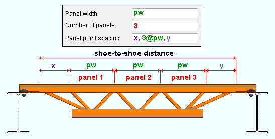
'
Automatic ' attempts to use the depth of the " Section size " as the panel width.
'
'
'
Panel member material: Automatic or Angle or Channel or Round bar . This " ![]() User preconfigured panel " option applies when the " Panel display method " is ' User pre-config '. Regardless of the choice made here, the panel material is dummy material .
User preconfigured panel " option applies when the " Panel display method " is ' User pre-config '. Regardless of the choice made here, the panel material is dummy material .
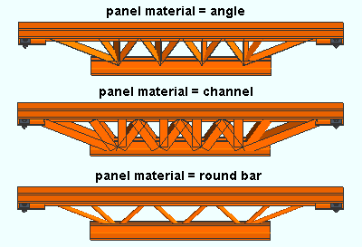
' Automatic ' looks at the joist type (K, KCS, LH, DLH, etc.) as described in this joist's " Section size ." It then looks at the the User pre-configured panel table at Home > Project Settings > Job > Joist Manufacturers to determine what material to use for that joist type. The table sets the section size (or rod diameter) of that material.
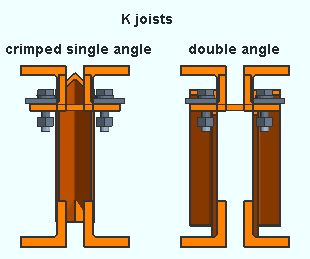
' Angle ' sets the diagonals in the joist panel to be angle material. The " Configuration " can be set to ' Automatic ' or ' Crimped single angle ' or ' Double angle '. The " Panel section size " is, by default, the angle size specified in Joist Manufacturers , or you can specify an angle section size of your own choosing.
' Channel ' sets the diagonals in the joist panel to be channel material. The " Panel section size " is, by default, the smallest available channel section size (e.g., ' MC3x7.1 '), or you can specify a channel section size of your own choosing.
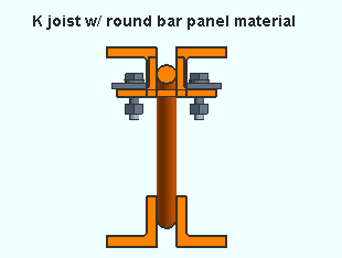
' Round bar ' sets the diagonals in the joist panel to be round bar material. The " Configuration " can be set to ' Auto filler thickness ' or ' User rod ' as described below.
Configuration : Available choices depend on whether the " Panel member material " is ' Angle ' or ' Round bar '.
|
' Automatic ' or ' Crimped single angle ' or ' Double angle ' apply when the " Panel member material " is ' Angle '. |
' Automatic ' reads the configuration specified at Home > Project Settings > Job > Joist Manufacturers .
' Crimped single angle ' specifies that each panel member is a single angle whose " Panel section size " is as specified below. This is a configuration commonly used in joist manufacturing. The angle centroids are oriented to prevent eccentricities and provide uniform distribution of loads. The crimped portion of the angles fit between the top or bottom chord materials.
' Double angle ' specifies that each diagonal in the joist consist of a NS angle and FS angle, with each such angle welded to the NS or FS top and bottom chord materials. Each angle is the " Panel section size " that is specified below.
|
' Auto filler thickness ' or ' User rod ' apply when the " Panel member material " is ' Round bar '. |
' Auto filler thickness ' lets the joist program determine the diameter of the round bar panel materials using the filler thickness assigned to the joist " Section size " in the local shape file.
' User rod ' lets you specify the " Panel section size " to be used for the round bar panel materials.
Panel section size : An angle section size or a round bar section size or a channel section size . Validation will not let you enter a section size that is not in the local shape file .
To enter an angle section size, the " Panel member material " must be ' Angle '. You can type in the angle section size , or you can press the "file cabinet" browse button (
To enter a round bar section size, the " Panel member material " must be ' Round bar '. You can type in the round bar section size , or you can press the "file cabinet" browse button (
To enter a channel section size, the " Panel member material " must be ' Channel '. You can type in the channel section size , or you can press the "file cabinet" browse button (
|
|
| End setting buttons : " Lock End " " Lock All Lockables " " Save As User Defined Connection " " Copy " " Paste " " Save " " Load " |
| Determining a member's left end : |
| Look at the location of its piecemark (B_2). |
| Look at its reference point ( |
| The left end is related to global coordinates . |
| Left end of a member in a plan view . |
| Left end of members in an elevation view . |
disables ( grays out ) all options under [ Left end settings ] or [ Right end settings ] (as the case may be), thus preventing users from making changes to the connection.
" Copy " and " Save " form buttons remain active. You can also still make changes to "
The material, hole, bolt and weld edit windows for system connection materials associated with this end of the member became read-only.
Furthermore, Delete or Erase cannot remove any of this connection's materials, holes, bolts or welds. Cut Layout , Add Holes , and similar material altering operations cannot be performed.
Locking a member's end does not stop you from applying Custom Properties to the locked connection material.
allows the options under [ Left end settings ] or [ Right end settings ] to be edited.
Status Update: Lock left/right end
Status Display: Approval and modeling > Member left end locked
![]() /
/ ![]() " Lock All Lockables"/"Unlock All Lockables "
" Lock All Lockables"/"Unlock All Lockables "
|
sets all "
) particular lockable fields (so that connection design can make entries to that field) or by you yourself making different entries to the locked fields.
![]() Save As User Defined Connection: This button is available when you are editing one member at a time. It is not available if you are editing multiple joists. It allows you to save as a user defined connection changes that you have made to connection design locks and to other [ Left end settings ] or [ Right end settings ]. You can overwrite a previously saved user defined connection or create an entirely new user defined connection.
Save As User Defined Connection: This button is available when you are editing one member at a time. It is not available if you are editing multiple joists. It allows you to save as a user defined connection changes that you have made to connection design locks and to other [ Left end settings ] or [ Right end settings ]. You can overwrite a previously saved user defined connection or create an entirely new user defined connection.
1. When you are done adjusting the connection's settings, click the Save As User Defined Connection button.2. The Select one User Defined Connection window opens. Click the New... button to create a new user defined connection using the current Connection specifications, connection design locks, and Moment options you have set.
Alternative 1: To save over an existing user defined connection and replace its settings with the current settings of the edit window, select it and click OK or double-click it. Click Yes or No on the prompt window asking if you want to overwrite the connection. The user defined connection is immediately saved. There are no further steps to take.
Alternative 2: Click the Cancel button to close the Select one User Defined Connection window.
3. The User defined connection name input window opens. Type in a name for the connection (61 characters max.) and click OK to save the new user defined connection.
Alternative: Click the Cancel button to close the User defined connection name input window and return to the Select one User Defined Connection window.
![]() " Copy " " Paste " " Save " " Load " buttons.
" Copy " " Paste " " Save " " Load " buttons.
|
|
|||||||||
|
|
||||||||
Connection: Force and/or Graphical or a System connection .
' Force ' applies when the connection has failed , which results in your not getting any connection materials in the 3D model.

forced 
system To get connection materials in the model so that you can assess the situation and make needed changes, check the box for "
A special application: Suppose you get the end connection failure message " Flush framed joist connection only valid for Vulcraft joists " instead of a ' Flushed frame shear ' connection. Checking the box for "
' Graphical ' may have been set to "

graphical system A graphical connection will not be changed by connection design . On this window, you will not be able to change any of that connection's " Connection design locks ." The Connection Design Calculations report (and Expanded Connection Design Calculations ) will include the warning " GRAPHICAL CONNECTION -- STRENGTH CALCULATIONS NOT GENERATED ." If "
Search and Change:
- Graphical Connections (a search)
- Change Graphically Altered to System Connections
- Change System to Graphically Altered Connections
- Change Force to System Connections
Report Writer: Member.LeftEnd.MoreEnd.Settings.ForceConnection
Report Writer: Member.LeftEnd.IsGraphicalConnectionAdvanced Selection: m.Ends[0].ForceConnection
Advanced Selection: m.Ends[0].IsGraphicalConnectionParametric module: m.Ends[0].ForceConnection
Parametric module: m.Ends[0].IsGraphicalConnection
The user locked message, connection failure messages, other messages :
If you are editing multiple joists and those joists have different connection failed or connection-changed messages, a banner like the following is displayed:
Multiple failed and/or changed connection messages The following banner notifies you that the connection has at least one " Connection design lock " setting that is locked (
):
Connection design locks set.
VIDEO Sections of a window (" leaves ") within which at least one locked variable resides are marked (in the navigation tree) with a locked icon ( Search: Connection design locks set
Status Display: Search > Connection design locks setYou may find a red connection failure banner like that shown below along with a
button for context-sensitive help about the message:
| Beam flange too narrow for joist bearing |
|
|
|
for help on the end connection failure message that is shown |
Report Writer: Member.LeftEnd.ConnectionHasFailed
Report Writer: Member.LeftEnd.MoreEnd.Conditions.ConnectionFailError
Advanced Selection: m.Ends[0].ConnectionHasFailed
Parametric module: m.Ends[0].ConnectionHasFailedYou may also get a connection changed message like the following:
| Conn changed. Possibly: Angle vs Plate |
Advanced Selection: m.Ends[0].DesignHasChanged
Parametric module: m.Ends[0].DesignHasChangedYou will find a yellow " Frames to ... " banner on this end of this joist if this end of the joist frames to a member (beam or column) that has its " Model complete date " set. The program may add the message (possible inaccurate connection) to the banner, or connection design may fail the connection on this end (the banner end) with the error message: Frames to a Model Complete member .
|
Frames to a Model Complete member
(possible inaccurate connection) |
|
|
|||||||||
|
|
||||||||
See the topic " Determining left end & near side " if you are unsure which end of this joist is the left end and which is the right end.
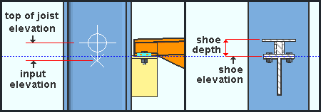
Top of joist : ![]() Automatic or
Automatic or ![]() Elevation or
Elevation or ![]() Elevation @ extension end .
Elevation @ extension end .
|
'
'
A joist in stick form with the " ) of the joist is at the " Top of joist " elevation of the left end of the joist.
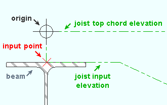
To determine the joist top chord elevation in the 3D model, use Construction Line Add or a similar tool, select EXPT as the Locate option, then snap the point location target to the top chord at either end of the joist. The Z coordinate reported in the X-Y-Z display tells you the elevation at the snapped-to exact point.
Note: The example above shows a joist-to-beam bearing connection. For a flush framed joist to a beam, the top-of-joist elevation that is entered here needs to match the top-of-steel elevation of the beam. If the top elevations don't match, connection design emits the failure message, Flush framed joist elevation not at supporting beam top of steel .
'
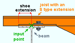
VIDEO A sloping joist is added. For " Top chord ," a ' Chord only (S type) extension ' is added and the ' Elevation @ extension end ' is adjusted for " Top of joist ."
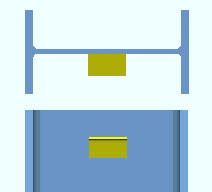
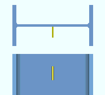
Supporting chord : Top or Bottom . Changing the choice that is made here may move the relevant end of the joist up or down.
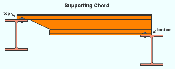
' Top ' specifies that it is the joist's top chord should connect to the supporting member at the " Input elevation " of the relevant end. In the industry, this is referred to as the "underslung end."
' Bottom ' specifies that it is the joist's bottom chord should connect to the supporting member at the " Input elevation " of the relevant end. In the industry, this is referred to as the "square end."
Bearing shoe: ![]() Automatic or
Automatic or ![]() Depth or
Depth or ![]() Elevation .
Elevation .
|
|
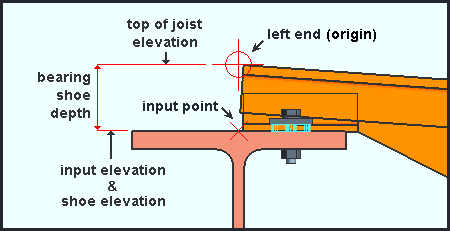
For a joist bearing connection, the input elevation and shoe elevation are the same, and therefore the fields that report those elevations are marked as linked.( |
|
For a joist seat, the input elevation and the shoe elevation are different, and therefore the fields that report those elevations are marked as unlinked ( |
'
'
'
) is shown. When the linked icon has been replaced with a not linked icon (
), you can edit this setting (bearing shoe " Elevation ") and the " Input elevation " separately. The two elevations are different -- not linked -- when the joist end has a seated connection.
Input elevation : The left- or right-end bearing elevation (a distance in the primary dimension " Units " or other units ). Changing this elevation moves the left- or right-end of the joist up or down. This is the elevation that will be used for node matching, framing situation checking and connection design. Consequently, if this elevation is not correct, the connection might fail.
|
|
This example shows a joist in stick form with the " |
To determine the input elevation on a Joist in the 3D model, use Construction Line Add or a similar tool, select EXPT as the Locate option, then snap the point location target to the X that is shown at the end of the joist. The Z coordinate reported in the X-Y-Z display tells you the elevation at the snapped-to exact point.
Note: The input point is marked with an X at both the left and right end of a joist. That point is an exact point ( EXPT ). This applies regardless of whether the joist is displayed in stick form, or in one of the three solid forms .
|
|
|||||||||
|
|
||||||||
|
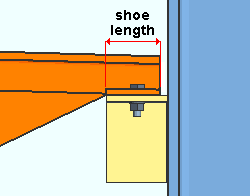
In this example, the " Shoe length " on the right end of the joist is set to " |
'
'
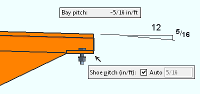
Shoe pitch ( in/ft or mm/250mm ) : ![]() Auto or
Auto or ![]() Auto . If the current Fabricator Setup " Units " are ' Imperial ', the " Shoe pitch " is reported in in/ft . For ' Metric ' units, the " Shoe pitch " is reported in mm/250 mm . Pitch can be positive (+) or negative (-).
Auto . If the current Fabricator Setup " Units " are ' Imperial ', the " Shoe pitch " is reported in in/ft . For ' Metric ' units, the " Shoe pitch " is reported in mm/250 mm . Pitch can be positive (+) or negative (-).
|
In this example, the " Shoe pitch " and " Bay pitch " have the same magnitude, but opposite signs. |
'
'
Top chord pitch ( in/ft or mm/250mm ) : ![]() Auto or
Auto or ![]() Auto . This "
Auto . This " ![]() Profile " option applies when the joist " Shape " is ' Double pitch ' or ' Scissor ' or ' Triple pitch '. If the current Fabricator Setup " Units " are ' Imperial ', the " Top chord pitch " is reported in in/ft . For ' Metric ' units, the " Top chord pitch " it is reported in mm/250 mm . Pitch can be positive (+) or negative (-).
Profile " option applies when the joist " Shape " is ' Double pitch ' or ' Scissor ' or ' Triple pitch '. If the current Fabricator Setup " Units " are ' Imperial ', the " Top chord pitch " is reported in in/ft . For ' Metric ' units, the " Top chord pitch " it is reported in mm/250 mm . Pitch can be positive (+) or negative (-).
|
On a triple pitch joist, a different " Top chord pitch " can be entered for the left end and the right end. When different pitches are entered, the center section of the joist is sloped. |
'
'
Bottom chord pitch ( in/ft or mm/250mm ) : ![]() Auto or
Auto or ![]() Auto .
Auto .
'
'
Triple pitch peak offset : ![]() Auto or
Auto or ![]() Auto . This "
Auto . This " ![]() Profile " option applies when the joist " Shape " is ' Triple pitch '.
Profile " option applies when the joist " Shape " is ' Triple pitch '.
'
'
|
|
|||||||||
|
|
||||||||
Input connection type: Auto standard or User defined or Plain end or Bearing or Seated or Flush framed shear or Flush framed clip angle .
|
|
| YouTube video: Flush Framed Joists. |
' Auto standard ' designs the connection on this end of the joist based on the joist's framing situation . Auto standard connections have a number of advantages .
If ' User defined ' is selected, the user defined connection file name must be entered to " User defined connection ."
' Plain end ' results in a system connection not being designed on this end of the joist. In pre-v2018 SDS2 software, ' Plain end ' could be selected to create a bearing connection. Now ' Bearing ' needs to be selected if you want connection design to attempt to create a bearing connection.
' Bearing ' can apply to a joist bearing on a beam flange or column cap plate. For a joist bearing on steel, the connection can be ' Bolted ' or ' Welded ' per " Chord-to-support " in "
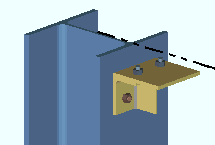
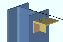
' Seated ' is the selection to make in order to get a top chord seated connection to a column web or flange. ' Plate ' or ' Unstiffened L ' or ' Stiffened L ' or ' Tee ' may then be selected as the " Top chord seated ."
' Flush framed shear ' can apply to a joist that is framed flush to a beam or column. The joist " Section size " should typically be a CJ series, though connection design can create a flush framed shear connection for other series. To get a flush framed shear connection without resorting to "
' Flush framed clip angle ' ( new ) can apply to a joist that is framed flush to a beam or column. You need to set " Joist manufacturer " to ' Vulcraft ' to get a connection without forcing it. The CJ series joist " Section size " is designed specifically for flush framed connections, but connection design can also create flush framed clip angle connections for other joist series.
Please note the following:
- Joists with flush framed connections do not have shoes. Joists with bearing or seated connections do have shoes.
- Process within member edit takes place immediately, at the time that an " Input connection type " is entered.
- "
- The " Design Calc " or " Expanded Calc " buttons give you the connection's design calculations.
Report Writer: Member.LeftEnd.MoreEnd.InputConnection.TypeDescription
Advanced Selection: m.Ends[0].Input.TypeDescription
Parametric module: m.Ends[0].Input.TypeDescription
Also see: The Connection Guide
User defined connection: The file name of the user defined connection in your current Job for this end of the joist.
To make an entry: You can type in the file name of the user defined connection that you want (if you know it), or you can press the "file cabinet" browse button (
) and double-click any user defined connection file name that is on the list.
Status Display: Connection type > Specific user defined connection
Report Writer: Member.Conditions.HasAUserDefinedConnection
Advanced Selection: m.Ends[0].FinalConnectionIsUserDefined
Parametric module: m.Ends[0].FinalConnectionIsUserDefined
System designed connection: read-only . This " ![]() Connection type " message tells you the type of connection that is designed on this end of the joist (e.g., ' Welded Joist ' or ' Bolted Joist ' or ' Seat '). If a connection has failed , resulting in no solids model being created, the connection type that connection design attempted to design will still be reported here.
Connection type " message tells you the type of connection that is designed on this end of the joist (e.g., ' Welded Joist ' or ' Bolted Joist ' or ' Seat '). If a connection has failed , resulting in no solids model being created, the connection type that connection design attempted to design will still be reported here.
The "System designed connection " may be different than the " Input connection type " for the following situations:
Conn changed. Possibly: Seated vs Plain end Report Writer: Member.LeftEnd.MoreEnd.DesignedConnection.TypeDescription
Advanced Selection: m.Ends[0].Designed.TypeDescription
Parametric module: m.Ends[0].Designed.TypeDescription
NM bolt type: Auto or A325N or A325SC or A325X or etc. NM stands for "non-moment." This bolt type is applied to " Top chord seated " connections and bolted " Chord to support " bearing connections and when the " Input connection type " is ' Flush framed shear ' or ' Flush framed clip ' or ' Auto standard ' or ' User defined '.
If the box for " Auto " is checked (
If the box for " Auto " is not checked (
). The bolt types that are listed come from Home > Project Settings > Job > Bolt Settings .
Advanced Selection: m.Ends[0].ConnectionDesignBoltTypeDescription
Parametric module: m.Ends[0].ConnectionDesignBoltTypeDescription
NM bolt diameter: Auto or a user-entered diameter . This " ![]() Connection type " option sets the diameter of the shanks of the bolts that are generated for " Top chord seated " connections and bolted " Chord to support " bearing connections and when the " Input connection type " is ' Flush framed shear ' or ' Flush framed clip ' or ' Auto standard ' or ' User defined '.
Connection type " option sets the diameter of the shanks of the bolts that are generated for " Top chord seated " connections and bolted " Chord to support " bearing connections and when the " Input connection type " is ' Flush framed shear ' or ' Flush framed clip ' or ' Auto standard ' or ' User defined '.
| diameter |
|
If the box for " Auto " is checked (
If the box for " Auto " is not checked (
Report Writer: Member.LeftEnd.MoreEnd.MinimumNonMomentBoltDiameter
Advanced Selection: m.Ends[0].MinimumNonMomentBoltDiameter
Parametric module: m.Ends[0].MinimumNonMomentBoltDiameter
Use miscellaneous plates list: ![]() or
or ![]() .
.
If this box is checked (
If the box is not checked (
Exception: Bottom chord extension plates are the thickness specified in setup.
Report Writer: Member.LeftEnd.MoreEnd.UseMiscellaneousPlates
Disable framing situation checks: ![]() or
or ![]() .
.
If this box is checked (
If the box is not checked (
|
|
|||||||||
|
|
||||||||
"
| Bearing (joist to beam or concrete)
(top of joist elevation must be at bearing shoe depth above beam's top of steel) |
|
| Chord to support | Top chord embed |
| Allow washers on shoe slots | Schedule entry |
| Extend bottom chord | Bottom chord embed |
| Stabilizing material | Schedule entry |
| Use erection hole | Location |
| Vertical stabilizer angle | |
| Seated (joist to column or concrete) | |
| Top chord seated material | Top chord embed |
| Seat to supporting member | Schedule entry |
| Allow washers on shoe slots | Location |
| Extend bottom chord | Bottom chord embed |
| Stabilizing material | Schedule entry |
| Stabilizing material | Location |
| Vertical stabilizer angle | |
| Flush framed shear (joist to beam or column)
(top of joist elevation at beam's top of steel) |
|
| Shear plate side | Use back-up bar |
| Extend past flange | Use alternate eccentricity |
| Extend stabilizer plates | Shear plate grade |
| Extend size to | Bevel shear plate as required |
| Stiffener opposite | Extend bottom chord |
| Try two bolt column shear tabs | Stabilizing material |
| Skew holes in plate | Use erection hole |
| Vertical stabilizer angle | |
| Flush framed clip (joist to beam or column)
(top of joist elevation at beam's top of steel) |
|
| Gage | Welded extended tee |
| Attachment to supported | Full depth extended tee |
| Attachment to supporting | Skew holes in angle |
| Side | Extend bottom chord |
| Use erection bolts | Stabilizing material |
| Safety connection | Use erection hole |
| Stagger on | Vertical stabilizer angle |
Chord to support: Bolted or Welded . This " ![]() Connection specifications " option applies to a joist's top chord or bottom chord bearing on a beam's top flange when ' Bearing ' has been entered to " Input connection type ."
Connection specifications " option applies to a joist's top chord or bottom chord bearing on a beam's top flange when ' Bearing ' has been entered to " Input connection type ."
' Bolted '
|
' Welded '
|
' Bolted ' instructs connection design to add holes and bolts to the beam flange for bolting the joist to the flange. The holes are included on the beam's member detail. The bolts can be included on Field Bolt reports and, optionally, on the beam's bill of material. The " Input elevation " of the joist must be the elevation of the beam's top flange in order for holes to be generated. The distance between the two holes is the " Top chord gage " entered in the local shape file . The choice made to " Wide flange beams, alternative gage for joist connections " or " Channel beams, alternative gage for joist connections " in Home > Project Settings > Fabricator > Standard Fabricator Connections > Joist Connection Settings set the placement of the holes with respect to the center of the beam web. Hole size is set using the " NM bolt diameter " in the "
' Welded ' sets the joist to be field welded. A 3D field weld is not generated. The design calculations note, " Joist end welded to supporting member ."
Connection design locks: Bearing Shoe Slots
Report Writer: Member.LeftEnd.BoltJoistEnd
Wide flange beam flange gage: local shape file
Alternative wide flange beam flange gage: Fabricator > Std Fab Conns > Joist Connection Settings (
Channel beam flange gage: local shape file
Alternative channel beam flange gage: Fabricator > Std Fab Conns > Joist Connection Settings
End connection failure messages: " Maximum joist bearing length exceeded " " Joist bearing bolts will not fit on beam flange "
Top chord seated material: Plate or Unstiffened L or Stiffened L or Tee . This " ![]() Connection specifications " option applies when ' Seated ' has been entered as the " Input connection type ." The joist seat will be detailed on (attached to) the wide flange or tube column that the joist frames to. Joist seats are not designed on pipe columns.
Connection specifications " option applies when ' Seated ' has been entered as the " Input connection type ." The joist seat will be detailed on (attached to) the wide flange or tube column that the joist frames to. Joist seats are not designed on pipe columns.
' Plate '

|
' Unstiff L '

|
' Stiffened L '

|
' Tee '

|
Note 1: If L (angle) or tee seats are to be designed, there must be angle or tee material entered to Home > Project Settings > Fabricator > Standard Fabricator Connections > Preferred Angle Sizes or Preferred WT Sizes . If no angle or tee material has been entered (or if an appropriate size is not listed), connection design defaults to plate material for the seat.
Note 2: Seats for a sloping joist are designed with their supporting surface horizontal (not sloping). Click here for an example.
Connection design locks: Seated Tee (for a joist top chord)
Connection design locks: Seated Plate (for a joist top chord)
Connection design locks: Seated Angle (for a joist top chord)Advanced Selection: m.Ends[0].Designed.SeatMaterial
Advanced Selection: m.Ends[0].Designed.IsStiffenedParametric module: m.Ends[0].Designed.SeatMaterial
Parametric module: m.Ends[0].Designed.IsStiffened
Seat to supporting member: Automatic or Bolted or Welded . This " ![]() Connection specifications " option applies when ' Unstiffened L ' or ' Stiffened L ' has been selected as the " Top chord seated material ."
Connection specifications " option applies when ' Unstiffened L ' or ' Stiffened L ' has been selected as the " Top chord seated material ."
' Bolted '
 |
' Welded '
|
' Automatic ' specifies that connection design apply the choice made to Home > Project Settings > Fabricator > Standard Fabricator Connections > Joist Connection Settings > " Angle seat to supporting member ."
' Bolted ' instructs connection design to shop bolt the angle seat to the supporting column and field bolt the supported joist to the seat. The seat is a submaterial of the column and is drawn on the column detail.
' Welded ' instructs connection design to shop weld the angle seat to the column and field bolt the joist to the seat. The seat is a submaterial of the column and is drawn on the column detail.
Advanced Selection: m.Ends[0].Designed.SeatToSupportingMember
Parametric module: m.Ends[0].Designed.SeatToSupportingMember
Allow washers on bearing shoe slots: Automatic or Yes or No . This " ![]() Connection specifications " option applies to a joist's top chord or bottom chord shoe slots when ' Bearing ' or ' Seated ' has been entered to " Input connection type ."
Connection specifications " option applies to a joist's top chord or bottom chord shoe slots when ' Bearing ' or ' Seated ' has been entered to " Input connection type ."
' Yes '
 |
' No '
|
' Automatic ' specifies that connection design apply the choice made to Home > Project Settings > Fabricator > Standard Fabricator Connections > Joist Connection Settings > " Allow washers on bearing shoe slots ."
' Yes ' instructs connection design to add material plate washers on bearing shoe slots for bolted joist bearing and seated connections.
' No ' instructs connection design not to add material plate washers on shoe slots.
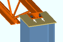
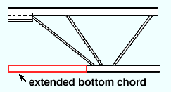
Extend bottom chord: ![]() or
or ![]() . This "
. This " ![]() Connection specifications " option and the related options " Stabilizing material " and " Use erection hole " and " Vertical stabilizer angle " are available when the joist end's " Input connection type " is ' Seated ' or ' Bearing ' or ' Flush framed shear '. " Extend bottom chord " and its related options are also available at Home > Project Settings > Job > Connections > Auto Standard Connections and User Defined Connections .
Connection specifications " option and the related options " Stabilizing material " and " Use erection hole " and " Vertical stabilizer angle " are available when the joist end's " Input connection type " is ' Seated ' or ' Bearing ' or ' Flush framed shear '. " Extend bottom chord " and its related options are also available at Home > Project Settings > Job > Connections > Auto Standard Connections and User Defined Connections .
If this box is checked (
If the box is not checked (
Stabilizing material: None or Angle or Plate . The plate/angle shop welds to the supporting member and field welds to the supported joist. 3D field weld is not generated. Only the shop weld to the column is shown in the model. Connection design changes the connection material from ' Angle ' to a ' Plate ' when the bottom chord extension connects to a pipe column.
' Angle '
|
' Plate '
|
' None ' results in no joist bottom chord stabilizing material being created by connection design.
' Angle ' instructs connection design to use the Home > Project Settings > Fabricator > Standard Fabricator Connections > " Bottom chord extension seat angle " as the angle seat for the extended bottom chord.
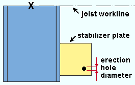
' Plate ' instructs connection design to use the Home > Project Settings > Fabricator > Standard Fabricator Connections > " Bottom chord extension plate " as the stabilizing material for the extended bottom chord. Per the OSHA standard, the plate includes a 13/16 inch (21 mm) hole (click here ) for guying or plumbing cables. The hole is placed 1 1/2 inch from the bottom edge and joist edge of the plate.
Use erection hole: Automatic or Yes or No . This "
|
" Use erection hole " sets whether or not a bottom chord stabilizer plate has an erection hole. |
' Automatic ' instructs connection design to use the entry (' Yes ' or ' No ') that is made to the relevant cell at Home > Project Settings > Fabricator > Standard Fabricator Connections > Joist Connection Settings > " Use erection hole " on the " Joist type specific settings " table. That setup table can configure an erection hole to be used or not used on a per-joist-type basis.
' Yes ' instructs connection design to add a hole for guying or plumbing cables to the bottom chord stabilizer plate. Per OSHA, the hole is placed 1 1/2 inch from the bottom edge and joist edge of the plate. A connection design lock for specifying the " Erection hole diameter " is made available in the "
' No ' instructs connection design to not add an erection hole.
Vertical stabilizer angle:
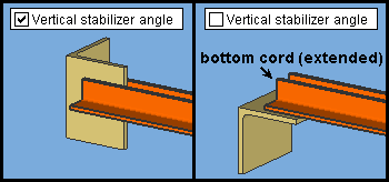
Regardless of the choice made here, the stabilizer angle shop welds to the supporting member.
If this box is checked (
If the box is not checked (
( This documentation also applies to auto standard and user defined connections. )
|
Schedule entry: A standard piecemark name from the " Piecemark " column in the Embed Schedule . An embed or bearing embed is not a designed connection, but is a separate custom member. Settings for that member do not appear in a leaf on this window. The top chord " Schedule entry " and its related options are available at Home > Project Settings > Job > Auto Standard Connections and at Home > Project Settings > Job > User Defined Connections as well as under "
A top chord " Schedule entry " can apply when the " Input connection type " is ' Seated ' and the joist frames to a concrete wall or to a tilt-up panel.
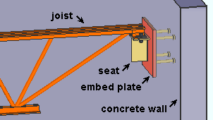
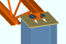
To get a top chord joist seat that welds to a custom member embed plate like the one shown here, you can select ' Seated ' as the " Input connection type ," then make a top chord embed " Schedule entry ." It is also required that the end of the joist frame to a concrete wall or to a tilt-up panel .
A top chord " Schedule entry " can also apply when the " Input connection type " is ' Bearing ' and the joist frames to a concrete wall or tilt-up panel.
Bearing embeds can be plates or angles or channels. In this example, it is a plate. The " Pocket grout thickness " in this example is ' 0 ' (zero), a value which places the embed flush with the bottom of the shoe.
To make an entry: Press the "file cabinet" browse button (
Connection design locks: "
Connection Guide: Joist top chord to concrete with pocket & bearing embed .
Connection Guide: Top chord joist seat to an embedLocation: Automatic or Inside wall or Outside wall . This option applies when a top chord " Schedule entry " has been entered (above). The top chord " Location " and its related options are available at Home > Project Settings > Job > Auto Standard Connections and at Home > Project Settings > Job > User Defined Connections as well as under "
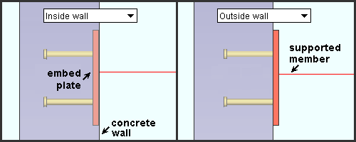
' Automatic ' specifies the automatic application of a setup choice ( Concrete Setup > Embed Schedule > " Plate location "). That setup choice sets whether the plate is located inside the concrete wall or flush to the surface of the wall.
' Inside wall ' embeds the plate in the concrete wall or tilt-up panel.
' Outside wall ' locates the plate flush to the wall or panel.
( This documentation also applies to auto standard and user defined connections. )
|
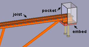
Schedule entry: A standard piecemark name from the " Piecemark " column in the Embed Schedule . This option applies when "
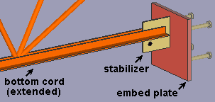
To get a bottom stabilizer that welds to a custom member embed plate like the one shown here, it is also required that the end of the joist frame to a concrete wall or to a tilt-up panel .
To make an entry: Press the "file cabinet" browse button (
Connection Guide: Extended joist bottom chord to an embed
Location: Automatic or Inside wall or Outside wall . This option applies to the bottom chord " Schedule entry " that is entered (above). The bottom chord " Location " and its related options are available at Home > Project Settings > Job > Auto Standard Connections and at Home > Project Settings > Job > User Defined Connections as well as under "
The "supported member" in this example is the extended bottom chord of the joist. Note that the embed plate is a custom member, not a part of the joist.
' Automatic ' specifies that connection design apply a setup choice ( Concrete Setup > Embed Schedule > " Plate location "). That setup choice sets whether the plate is located inside the concrete wall or flush to the surface of the wall.
' Inside wall ' embeds the plate in the concrete wall or tilt-up panel .
' Outside wall ' locates the plate flush to the wall or panel.
|
|
|||||||||
|
|
||||||||
Top chord : ' ![]() Auto or
Auto or ![]() Chord only (S type) extension or
Chord only (S type) extension or ![]() Full (R type) extension or
Full (R type) extension or ![]() Field clearance or
Field clearance or ![]() Setback . All of these dimensions require that you enter a positive distance from the input point. All except '
Setback . All of these dimensions require that you enter a positive distance from the input point. All except ' ![]() Field clearance ' are horizontal dimensions. '
Field clearance ' are horizontal dimensions. ' ![]() Field clearance ' is measured parallel with the slope of the joist.
Field clearance ' is measured parallel with the slope of the joist.
|
'
'
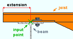
Even if the joist slopes, this dimension is measured horizontally. A " Shoe " extension can optionally be applied to a ' Chord only (S type) extension '. '
Even if the joist slopes, this dimension is measured horizontally. '
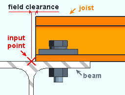
For a joist to beam ' Bearing ' connection, the field clearance is the distance parallel with the member line of the joist (in the primary dimension " Units " or other units ) from the input point of the joist ( X ) to the top of the joist's top chord. This distance is measured along the top of the joist's top chord.
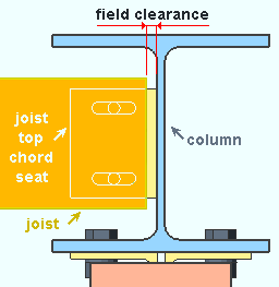
For a joist seat, the field clearance is the distance parallel with the member line of the joist (in the primary dimension " Units " or other units ) from the top edge of the joist's top chord to the face of the supporting member. '
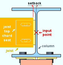
The setback is the horizontal distance (in the primary dimension " Units " or other units ) from the input point to the edge of the joist. For a seated connection, the field clearance and setback are different dimensions.
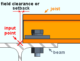
For a horizontal joist bearing on a web vertical beam's top flange, the setback is equal to the field clearance. Flush framed connection fail message: User top chord setback less than minimum required
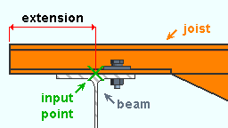
Shoe : ' ![]() Auto or
Auto or ![]() Extension or
Extension or ![]() Field clearance or
Field clearance or ![]() Setback . These dimensions position the top chord left- or right-end shoe. They require that you enter a positive distance from the input point. '
Setback . These dimensions position the top chord left- or right-end shoe. They require that you enter a positive distance from the input point. ' ![]() Extension ' and '
Extension ' and ' ![]() Setback ' are horizontal dimensions. '
Setback ' are horizontal dimensions. ' ![]() Field clearance ' is measured parallel with the slope of the joist.
Field clearance ' is measured parallel with the slope of the joist.
'
'
Even if the joist slopes, this dimension is measured horizontally. A " Shoe " extension can optionally be applied to a ' Chord only (S type) extension '. '
For a joist to beam ' Bearing ' connection, the shoe field clearance is the distance parallel with the member line of the joist (in the primary dimension " Units " or other units ) from the input point of the joist ( X ) to the edge of the shoe.
For a joist seat (not shown), the shoe field clearance is the distance parallel with the member line of the joist (in the primary dimension " Units " or other units ) from the edge of the shoe to the face of the supporting member. '
Bottom chord : ' ![]() Auto or
Auto or ![]() Extension or
Extension or ![]() Field clearance or
Field clearance or ![]() Setback . All of these dimensions require that you enter a positive distance from the input point. '
Setback . All of these dimensions require that you enter a positive distance from the input point. ' ![]() Extension ' and '
Extension ' and ' ![]() Setback ' are horizontal dimensions. '
Setback ' are horizontal dimensions. ' ![]() Field clearance ' is measured parallel with the slope of the joist.
Field clearance ' is measured parallel with the slope of the joist.
|
'
An '
A '
A '
|
|
|||||||||||
|
|
||||||||||
Load (kips or kN) : The load on this end of the joist in kips ( kilonewtons for ' Metric '). The loads for each end of a joist must be entered for connection design to be able to do the proper calculations when designing an " Input connection type " other than ' Plain end '.
|
|
|||||||||||
|
|
||||||||||
- A left- and right-end " Summary " leaf can be shown on this window only if you are editing one joist. There is no summary if you are editing multiple joists.
- The leaf gives you a summary of connection information related to the left or right end of the joist.
- The summary shows (in parentheses) the " System designed connection " on that end of the joist.
- If other joists have been assigned the same piecemark as this joist, the summary will list those other joists by member number . These are the joists that will be changed if, after you close this window, you press the " Yes " button when prompted to change all .
- " Connection design locks " on this window that were locked ( ) because the " Input connection type " is ' User defined ' are reported as " Locked Via User Defined ." All other locks on this window that are locked ( ) are reported as " Locked Via Member Edit ."
- Here's a couple of ways to track a piecemark count:
Advanced Selection: m.PiecemarkCount
Parametric module: m.PiecemarkCount
|
|
|||||||||||
|
|
||||||||||
|
|||||||||||||||||
- Locked ( ) connection design locks are entries made by users.
- Unlocked (
 ) connection design locks are values entered by connection design . Many of the unlocked fields are populated based on user-entered setup choices.
- Changing a locked ( ) setting or locking/unlocking a field triggers connection design to recreate the connection and update the limit state information. The limit state information tells you the capacity of the designed connection.
- These same connection design locks may also be found (and revised) on the Connection Component Edit window for this connection.
- When checked, " Show images " displays drawings for connection design locks.
- Here's some ways to track connection design locks:
Status Display: Search > Connection design locks set
Search: Connection design locks set .
Design Calculations Report: Connection Design Lock Summary
|
|
|||||||||
|
|
||||||||
|
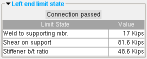
The limit states for a seated plate connection on the left end of a joist. In this example, the connection passes. |
|
- A limit state is a potential connection failure mode. Each " Value " reported in the example above represents the strength of the connection or of the joist itself or of its supporting member with respect to a particular limit state.
- The capacity of a connection is calculated for various limit states during connection design , and the left-end and/or right-end limit states tables on this window will be updated any time that connection design takes place.
- When Process within member edit is turned on, node matching, connection design and framing situation checking takes place within this window, whenever you change a Connection specification or a load or a connection design lock or any other connection-related setting.
- If connection design determines that the capacity of an end connection is insufficient to stand up to the " Loads " on a member end, it fails the connection and generates an end connection failure message.
- When you make changes to connection design locks , referring to the reported limit states can help you to better assess how your changes affect the capacity of the connection.
- The Expanded Connection Design Calculations provides formulas and the calculations that relate limit states to the design of the specific connection.
"Copy" "Paste" "Save" "Load" apply to all fields on this window. They do the same thing as the "Copy" "Paste" "Save" "Load" buttons ( ![]() ) found above individual leaves on this window -- except that they apply to the entire window instead of individual leaves or sections.
) found above individual leaves on this window -- except that they apply to the entire window instead of individual leaves or sections.
"Properties" opens the Edit Properties window, on which you can make entries to custom properties . If, at the time it was created, your current Job was set to use a legacy flavor, the window that opens is named Custom Properties , not Edit Properties .
The Edit Properties window can also be used to read "
Tip: Model > Member > Properties is an alternative to this button. It opens the Edit Properties window directly, without your first having to open a member edit window.
" Status " opens the Status Review window, which can give you additional information about this joist, and which you can use to enter status information.
Note: This button is orange if one or more " Repeat " check boxes on the Member Status Review window do not match the checked-unchecked state of same-named fields in User and Site Options > Site > " Items to Copy/Repeat ." On the Status Review window, the fields that do not match User and Site Options are printed in red .
" OK " (or the Enter key) closes the Joist Edit window and saves any changes made on the window to the member file of the affected joist.
Solids on "OK": If the appropriate choice is made to User and Site Options > Modeling > " Automatically process after modeling operation ," then this joist's end connections will automatically be regenerated ( Create Solids will take place) after your press " OK ." Otherwise, you can manually Process and Create Solids in order for changes you made on this window to be fully updated in the 3D model.
Change all: If you Edit Member (one joist only) and make a change that potentially triggers the " Do you want to change all ... " dialog and the 3D model contains more than one joist that has the same piecemark as the joist you changed, a yes-no dialog opens. On it is the question, " Do you want to change all (members with this piecemark). " Press the " Yes " button to change all the members; press the " No " button to change only this joist. Special cases are listed on the table below:
Do not trigger change all ... Not changed with change all ... " Sequence " " Sequence " " Piecemark " " Load " settings " Member category " " Model complete date " " Member description " Example: " Yes " or " No " on the dialog changes the " Sequence " of this member (1 joist) only. " Member routes " " Model complete date " Defaults for to-be-added joists: If you are adding a joist and press " OK ," the settings on this window become the default settings for the next joist you Add in this session of Modeling . Even if all you do is double-click a joist and press " OK " without making any changes on this window, this window's settings become the defaults for the next-added joist. On the other hand, the settings on this window do not become the defaults for new joists if you are editing multiple piecemarks or if you press " Cancel " to close this window.
" Cancel " (or the Esc key or the ![]() button) closes this window without saving any changes.
button) closes this window without saving any changes.
Note: If you opened this window using Add Joist , pressing " Cancel ," brings you back to the work point location step of adding a joist.
Tip: Any time you Edit Member just to review a member (and you do not want to set the defaults for to-be-added members), the best way to close this window is to press " Cancel. "
" Reset " undoes all changes made since you first opened this window.
"Design Calc" outputs the Design Calculations report (also referred to as Short Calcs) which includes design calculations, general settings, and left/right end settings. A report for each joist you are editing is output to a destination of your choice as a PDF file. The file automatically opens with your operating system's default PDF application when you are editing one joist at a time.
"Expanded Calc" outputs the Expanded Connection Design Calculations . First a PDF of the report is output to a destination of your choice. For example, to your desktop. Then the report automatically opens with your operating system's default PDF application.
Expanded Connection Design Calculations give you the calculation results found in the Connection Design Calculations , plus show you the calculations written out, in detail, in the report itself, instead of simply reporting the results.
If you are editing multiple joists with the same piecemark (or different piecemarks), you get a report for each brace.
Connection design failures can be found with the aid of a search or by a quick scan of the document. Calculations that result in a connection failure are identified as " (NO GOOD) " in their concluding line. You might also search for the string "CONNECTION DESIGN FAILURE".

