v2023 Enhancements
- Cut Layout Material Operation
- Surface Finishes
- Bracing Connections (video)
- Hole Options (video)
- End Reactions on Drawings (video)
- Expanded Staggering Options (video)
- Expanded Stiffeners for Base/Cap Plate Connections (video)
- Remove Hidden Lines on Handrails (video)
Cut Layout Material Operation
Watch a video tutorial here.
SDS2 2023 adds Cut Layout to the list of Material Operations that are saved as a 3D object, which can be seen, edited, and deleted on the material. When a change is made to a material with a Cut Layout material operation and the material is regenerated, the Cut Layout material operation remains on the material. In previous versions, the Cut Layout would be lost.
Modifying Material Operations
The Material Operations window can be accessed from the Material Edit window by clicking the “Material Operations” button.

The Material Operations window allows you to Edit, Show, or Delete the selected Cut Layout material operation.
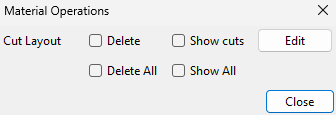
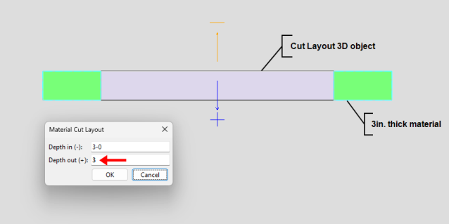
Clicking the Edit button opens the Material Cut Layout window, which allows you to change the Depth in (-) and Depth out (+) of the Cut Layout 3D object.
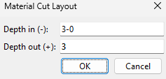
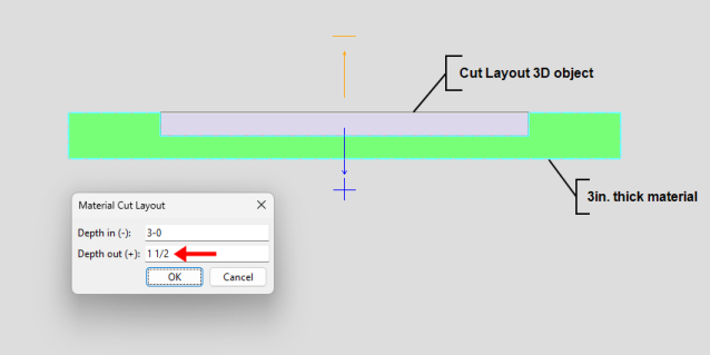
The Depth in (-) and Depth out (+) settings could affect the thickness of the material operations object. The thickness of the material operations object will not exceed the material thickness no matter what is set here. The thickness of the material operations object can be less than the material thickness if you do not want to cut all the way through the material thickness. While the Material Cut Layout window is open, a helpful graphical reference appears in the model showing the direction of each setting.
|
|
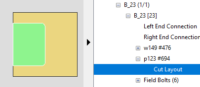
The Cut Layout operation can also be selected from the Model Tree. Selecting Cut Layout in the Model Tree will also select the material operations object in the model. While Cut Layout is selected in the Model Tree, the object will be shown in the model if it is not already shown using Show Material Operations. The object will return to a hidden state after clearing your selection in the Model Tree. Double-click either Cut Layout in the Model Tree or the material operations object in the model to open the Material Cut Layout window. Alternatively, you can right-click Cut Layout in the Model Tree and choose " Edit " from the shortcut menu to open the Material Cut Layout window
Tools
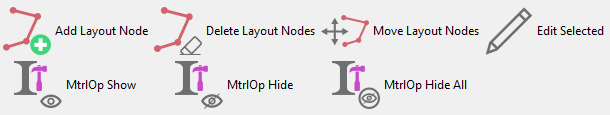
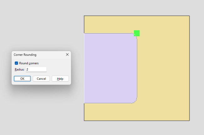
Alterations can now be made to existing Cut Layout material operations using new and old tools in SDS2 2023. New in SDS2 2023, a layout node is created at each point that is located when initially creating the Cut Layout. Layout nodes can be added, deleted, and moved in order to change the shape of the existing Cut Layout material operation. They can also be edited to toggle round corners and to change the radius. Layout nodes are only selectable when the material operation is shown using Show Material Operations. The material operation can be hidden using Hide Material Operations or Hide All Material Operations.
-
Add Layout Nodes (New in SDS2 2023)
-
Delete Layout Nodes (New in SDS2 2023)
Surface Finishes
Watch a video tutorial here.
SDS2 2023 has added more functionality for material surface finishes. Surface finishes are nothing new inside of SDS2. However, these new changes affect the way Surface finishes are incorporated in 2023. Surface finish can be controlled at the member or material level. This also includes options to create new surface finishes, hide the default finishes, and more.
Member Edit
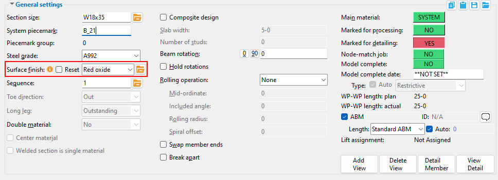
Surface finish has been added to the member edit screen inside of General Settings. The selected surface finish at the member level passes down to all attached submaterials that are set to auto.
The checkbox ( ![]() ) for reset, resets all attached submaterials' auto checkbox , which then matches the member's finish that is selected. This finish is available in all member edit windows.
) for reset, resets all attached submaterials' auto checkbox , which then matches the member's finish that is selected. This finish is available in all member edit windows.
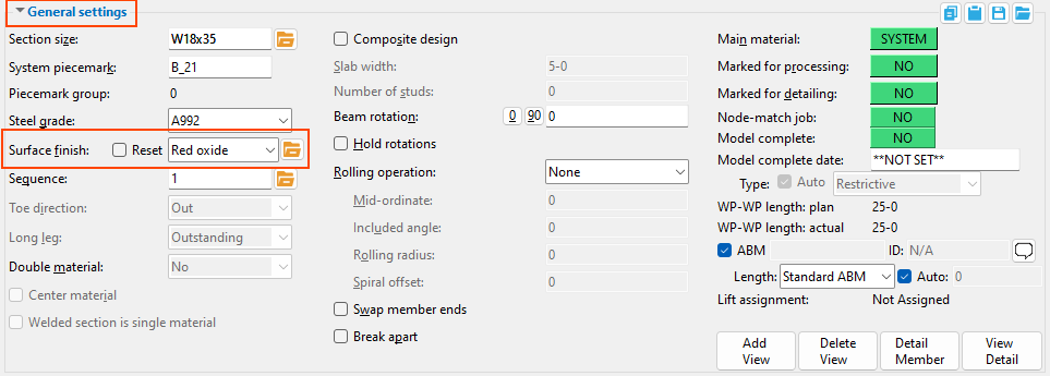
If any material attached to the member has a surface finish that is different from what is set in the member edit window, there is an information note next to the reset checkbox. Hovering over the note reads "Submaterials have user surface finishes". If you need to reset this, you can either check on the Reset checkbox within the member edit or you can check the Auto checkbox within the material edit window.
Material Edit
Surface finish remains in the material edit window. This works similar to how it did in the past, however there is now a browse option, as well as an auto checkbox ( ![]() ).
).
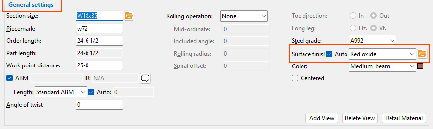
If the auto checkbox ( ![]() ) is checked, it follows what is set on the member level. If the surface finish changes from what the member level has set, the auto checkbox will be unchecked. When a material is manually changed to not match the member surface finish, the member edit window shows an information tag. This tag notifies the user that an attached material is not following what was set on the member level.
) is checked, it follows what is set on the member level. If the surface finish changes from what the member level has set, the auto checkbox will be unchecked. When a material is manually changed to not match the member surface finish, the member edit window shows an information tag. This tag notifies the user that an attached material is not following what was set on the member level.
Project Settings
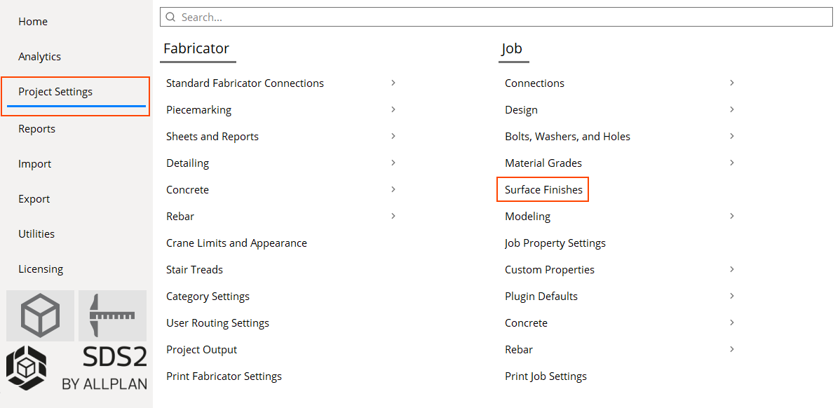
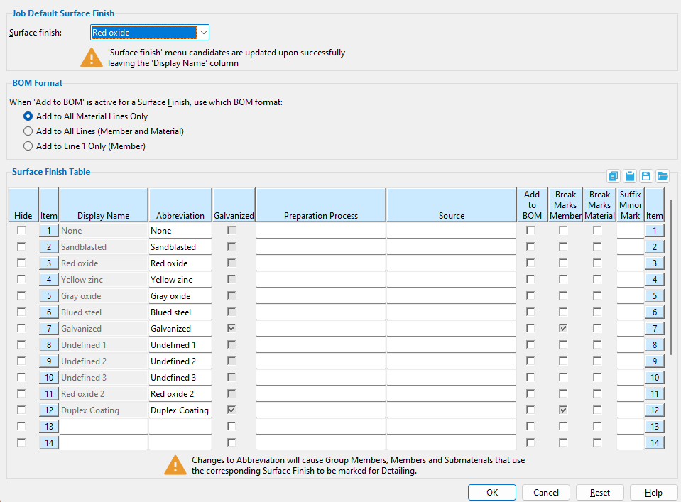
This is a brand-new setting inside of SDS2 2023. In this settings window, you have multiple options for surface finishes.
-
The first option is for job default surface finish. This can be changed and applies to any member that is added after this has been set.
-
The BOM Format specifies how the surface finish will show up in the bill of material when detailed. To have this show, the checkbox for Add to BOM must be checked and have a plot order set for Surface Finishes in bill of material layout.
-
There are 12 finishes by default, these are the same that have been used in previous versions of SDS2. The first 12 surface finishes' display name and galvanizing options are not editable. These are here for when a project is converted so there will not be any issues with the finishes not matching. If these finishes are not wanted, the first setting (Hide checkbox) in the surface finish table gives the ability to hide these finishes. This checkbox prevents the finish from being displayed in the surface finish combo box within modeling.
-
The abbreviation is how this finish will show in the bill of material, assuming the plot order is set in the bill of material layout. MRP exports will use this abbreviation if it is changed by the user. Exports like KISS that have always exported simplified nomenclature for the finishes will remain doing so, unless the user manually changes the abbreviations for the default finishes here.
-
Galvanized sets this finish as a galvanized finish or not. When set as a galvanized finish, it applies any Galvanizing Settings to the member/material.
-
The preparation process and source are used mostly for report writer, standalone reports or tables in drawing editor, and advanced selection. The preparation process is typically for cleaning or preparation purposes while the source would really be for where you are getting the finish materials from. The preparation process or source will not cause piecemarks to change, or break apart.
-
Add to BOM allows for this finish to be shown in the BOM. You need to ensure Surface Finishes has an active plot order in your Bill of Material Layout.
-
Break Marks Member will break apart the member piecemarks, based on the surface finish, if this checkbox is checked.
-
Break Marks Material will break apart the submaterial piecemarks, base on the surface finish, if this checkbox is checked.
-
The option for Suffix Minor Mark will add the string of text which is typed here to the end of the material mark. This option will only apply to standard piecemarks.
BOM Layout
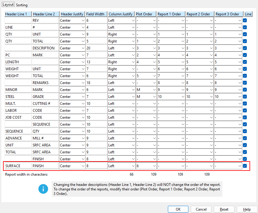
Inside of the BOM layout (Project settings > fabricator settings > Sheets and Reports > Bill of Material Layout), there is a new option for Surface Finish. To have the surface finish shown in the bill of material, both the Plot Order must be set and Add to BOM must be checked.

