"  Stability Plate " connection design locks
| Stability plates for beam-to-column-web shear plate connections can be designed per " |
|
|||
"  |
|
||
Connection Guide: Click here .
User Defined Connections: Settings that are locked (
) in a user defined connection file will automatically be locked on a member edit window for which that file is the " Input connection type ." You can, if you so choose, manually lock additional settings on the member edit window, and your changes will be retained, through multiple processes, so long as you do not change to a different connection then switch back to the original user defined connection.
Beam Edit: To change a setting, first set it to locked (
). Related settings that are unlocked (
) may be updated, and the "
Left/Right end limit state " calculations will be updated. Settings that are locked (
) will not be changed by connection design , even if doing so might prevent a connection failure.
Connection design locks :
| Locks not dimensioned or called out on the drawing are marked ( not depicted ). |
![]() Stability Plate
Stability Plate
Top/bottom stability plates
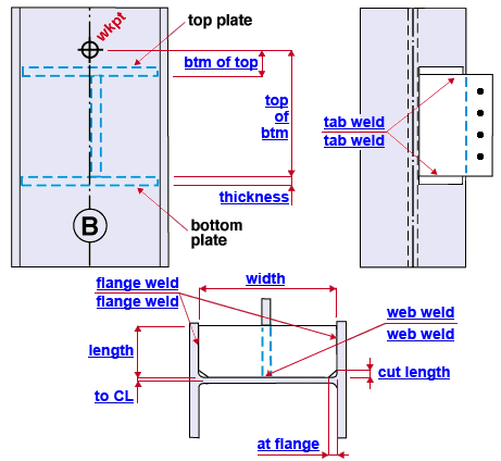
Tab to plate weld ( tab weld ): The weld size for shop welding the shear tab to the top/bottom stability plates (see example ). Setting this to ' 0 ' removes the weld.
Column CL to plate ( to CL ): The distance from the center of the column web to the closest edge of the top/bottom stability plate. In the example above, this distance is half the column web thickness since the plate is flush to the column web.
Top plate
Bottom of top plate ( btm of top ): The distance (parallel with the work line of the column) from the work point of the supported beam (which aligns with the beam's top flange) to the bottom face of the top stability plate. See example .
Plate length ( length ): The distance (perpendicular to the work line of the column) from the edge of the top/bottom stability plate that frames to the column web to the opposite, parallel edge that is farthest from the column web. See the example .
Plate width ( width ): The distance (perpendicular to the work line of the column) from the edge of the top/bottom stability plate that frames to one column flange to the edge that frames to the opposite column flange. See the example .
Plate thickness ( thickness ): The " Material thickness " of the top stability plates. See the example .
Corner clip/cope length ( cut length ): This applies to each of the cuts at the two corners of the edge of the stability plate that frame to the column. Whether the cut is a clip or cope depends on whether ' Clip ' or ' Cope ' is selected for the option " Corner operation for flange stiffeners " in Moment Plate Design Settings setup. The distance that is entered here is measured parallel with the " Plate length ." In the example above, a corner clip is used to clear the fillet where the web and flange of the column meet; this cut would not be needed if the " Col CL to plate " distance is sufficiently large. ' 0 ' results in a square corner (no corner clip). Click here for examples of two types of stability plates. Only the one of these types requires a corner cut to clear the web fillet.
Corner clip/cope length at flange ( at flange ): Same as " Corner clip/cope length ," except that this distance sets the length of the cut parallel with the " Plate width ."
Plate to column web weld ( web weld ): The weld size used to shop weld the top stability plate to the column web. See the example . Setting this to ' 0 ' removes the weld. You might remove the weld, for example, if " Col CL to plate " is large enough that the stability plate is no longer flush to the column web. Click here for examples of two types of stability plates. Only the one of these types requires a weld.
Plate to column flange weld ( flange weld ): The weld size used to shop weld the top/bottom stability plate to the column flange. See the example . Setting this to ' 0 ' removes the weld.
Bottom plate
Top of bottom plate ( top of btm ): The distance (parallel with the work line of the column) from the work point of the supported beam (in alignment with the beam's top flange) to the top of the bottom stability plate. See the example .
Plate length: Same as the " Plate length " for the top plate, except that this applies to the bottom stability plate.
Plate width: Same as the " Plate width " for the top plate, except that this applies to the bottom stability plate.
Plate thickness: See " Plate thickness " for the top plate.
Corner clip/cope length: See " Corner clip/cope length " for the top stability plate.
Corner clip/cope length at flange: See " Corner clip/cope length at flange " for the top stability plate.
Plate to column web weld: See " Plate to column web weld " for the top stability plate.
Plate to column flange weld: See " Plate to column flange weld " for the top stability plate.


