"  Gusset Column Cap Square " & " Brace Connection To Gusset " & " Weld Conn2 " & " Weld Conn1 " connection design locks
| An L (shown) or stem-vertical WT or C vertical brace field bolts directly to a gusset plate that shop attaches to a column & base plate (shown) or a column & cap plate (not shown) per " |
|
|||
| " (gusset dimensions and location) 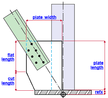 |
" (cuts to the gusset plate) 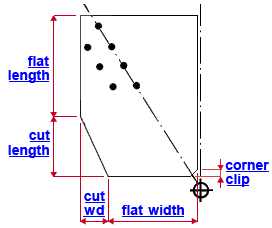 |
||
| " (holes for field bolting the brace to the gusset) 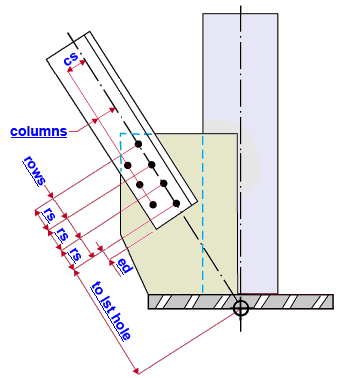 |
" (shop weld, gusset plate to the column and to the column plate) 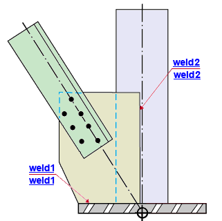 |
||
|
|||
User Defined Connections: Settings that are locked (
) in the user defined connection file will automatically be locked on the member edit window. You can, if you so choose, manually lock additional settings on the member edit window, and your changes will be retained, through multiple processes, so long as you do not change to a different connection then switch back to the original user defined connection.
Vertical Brace Edit: To change a setting, first set it to locked (
) may be updated, and the "
Connection design locks :
| Locks not dimensioned or called out on the drawing are marked ( not depicted ). |
![]() Gusset Column Cap Square
Gusset Column Cap Square
(angle vertical brace to a column & base/cap plate)
(" Clip end operation " = ' No ' or possibly ' Automatic ')
Plate thickness ( not depicted ): The " Material thickness " of the gusset plate.
Width ( plate width ): The distance from the framing edge of the gusset plate (which welds to the supporting column in the above example ) to the edge opposite to and parallel to that edge. For a column that is perfectly vertical, the framing edge is vertical and the gusset plate " Width " is horizontal. The gusset plate " Width " is also the length of the top edge of the gusset plate.
Length ( plate length ): The length of the framing edge of the gusset plate (the edge that is shop welded to the supporting column in the example above). The gusset plate " Length " is measured parallel with the work line of the supporting column. For a vertical column, this distance is vertical.
Refx : The positive (+) or negative (-) distance (parallel with the work line of the supporting column) from the work point of the vertical brace to edge of the gusset plate that welds to the base plate. If the supporting column is vertical, this distance is vertical. In the example above, this distance matches the thickness of the base plate. Increasing the " Refx " in this example would move the gusset plate vertically, adding a gap between the gusset and the base plate. A " Refx " of ' 0 ' lines up the corner of the gusset plate with the work point on this end of the vertical brace. Entering a positive (+) distance moves the corner of the gusset plate parallel with the column toward the opposite end to which the column plate is attached. Entering a negative (-) distance moves the gusset plate parallel with the column in the direction of the column plate. Changing the " Refx " moves the gusset plate, but does not move the holes in the gusset plate.
Refy ( not depicted ): The positive (+) or negative (-) distance (perpendicular to the supporting column) from the work point for this end of the vertical brace to the edge of the gusset plate that welds to the column (see example ). If the supporting column is vertical, this distance is horizontal. A " Refy " of ' 0 ' aligns the edge of the gusset plate that welds to the column with the work point. Entering a positive (+) distance moves the gusset plate perpendicular to the column toward the opposite end of the vertical brace. Entering a negative (-) distance moves the gusset plate perpendicular to the column in the direction that this end of the horizontal brace points toward. Changing the " Refy " moves the gusset plate, but does not move the holes on the plate.
Beam side clip cut width ( cut wd ): As shown in the example above, the work line of the brace divides the gusset plate into a column side and a beam side (even if there is no beam). This is the distance (perpendicular to the work line of the supporting column) from the " Flat length " edge of the plate to the end of this cut.
Beam side clip cut length ( cut length): As shown in the example above, the work line of the brace divides the gusset plate into a column side and a beam side (even if there is no beam). This is the distance (parallel with the work line of the supporting column) from the base plate or cap plate to the end of this cut (which is where the " Flat length " edge begins).
Flat length: The distance (parallel with the work line of the supporting column) from the " Width " edge of the gusset plate to where the " Beam side clip cut " begins. The " Width " edge of the gusset plate referred to here is the " Width " edge that is opposite to the " Flat width " edge, which abuts to the base plate or cap plate. See the example above.
Flat width: The distance (perpendicular to the work line of the supporting column) from the corner of the beam side clip cut to the corner of the gusset plate that is nearest the column plate and column. In other words, this is the length the edge of the gusset plate that abuts the column plate. The " Flat width " dimension does not account for material removed by designating a " Corner clip " dimension.
Corner clip: A distance entered here results in a 45 degree clip cut to the gusset plate at the corner where the gusset plate, column plate and column meet. A " Corner clip " of ' 0 ' keeps the corner square. The corner clip distance is measured perpendicular to or parallel with the work line of the supporting column, from one corner of the clip cut to the other.
![]() Brace Connection To Gusset
Brace Connection To Gusset
(L or WT or C vertical brace to a column & base/cap plate)
Brace connection to the gusset plate (field bolted)
Bolt diameter ( not depicted ): You can either type in any diameter (inches or mm), or you can select a bolt diameter from the combo box (
). The diameters that are listed in the combo box come from Home > Project Settings > Job > Bolt Settings > the " Available bolt diameters " list. The bolt diameter entered here, together with the " Hole type " entered below, set the diameter of holes the bolts go into.
Hole type ( not depicted ): Standard round or Short slot or Oversized or Long slot or User slot #1 or User slot #2 . The hole type selected here, together with the " Bolt diameter " entered above, set the diameter of holes for field bolting the brace to the gusset plate.

Rows: The number of holes in the column of holes with the greatest number of holes. For an angle vertical brace, this is the number of rows of holes in the column of holes along the work line of the brace. For vertical braces of other types of material, this is the number of rows in any one column of holes. Entering ' 0 ' removes the holes. For the angle brace shown in the example above, the number of " Rows " is ' 4 '.
Distance to 1st hole along brace ( to 1st hole ): The distance (parallel with the work line of the brace) from the work point of the vertical brace to the center of the nearest row of holes. For the example above (an angle brace with staggered bolts), the nearest row of holes is the nearest hole on the work line.
Hole spacing along brace ( rs ): Row spacing. This is the distance (center to center) between of any two adjacent holes in the same column of holes (see example ). Bolt row spacing on a vertical brace gusset plate runs parallel with the work line of the vertical brace.
End connection failure message: Invalid bolt spacing
Edge distance along brace ( ed ): The distance from the forward edge of the angle brace to the nearest hole in the brace. This distance is measured along the work line of the vertical brace. The forward edge of the angle brace is the edge that is closest to the brace work point. In other words, it is the edge that is closest to the supporting column and base/cap plate.
Columns: The number of columns of holes on the gusset plate. These holes will be used for field bolting the vertical brace to the gusset. In the example above, the number of " Columns " is ' 2 '.
Hole spacing perpendicular to brace ( cs ): Column spacing. This is the distance (center to center) between any two columns of holes (see example ). To get a single column of holes, enter ' 0 ' as the " Column spacing ." Bolt column spacing runs perpendicular to the work line of the vertical brace. Holes within an individual column run parallel with the work line.
![]() Weld Conn2
Weld Conn2
(L or WT or C vertical brace to a column & user base/cap plate)
Shop weld, gusset to the supporting column
Weld size ( weld2 ): The weld size for shop welding the gusset plate to the supporting column (see example ). A vertical brace gusset plate to a column and its base/cap plate is normally shop welded to (and detailed with) the column and field bolted to the vertical brace.
![]() Weld Conn1
Weld Conn1
(L or WT or C vertical brace to a column & base/cap plate)
Shop weld, gusset to the column plate
Weld size ( weld1 ): The weld size for shop welding the gusset plate to the base plate or cap plate (see example ). A vertical brace gusset plate to a column and its base plate or cap plate is normally shop welded to (and detailed with) the column and field bolted to the vertical brace.
For an auto base/cap plate: When the " Input connection type " for the column is ' Auto base/cap plate ', the " Weld size " connection design lock found on the Vertical Brace Edit window under "

