Joist Connection Settings
- General Overview
- Tips and Tricks
- Related Tools
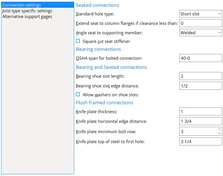
Seated connections
Standard hole type : Standard round or Short slot or Long slot or Oversized round or User slot #1 or User slot #2 .

Effect on Modeling: Connection design of a joist seat determines the specific size and shape of holes in the seat from the hole type entered here and the diameter of the bolt that is used. The default bolt diameter is set on a per-joist-type basis, under " Default bolt criteria " in Bolt Settings ( Home > Project Settings > Job > Bolts, Washers, and Holes ).
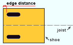
Please note: The hole type in the joist shoe is a long slot whose length is the " Bearing shoe slot length ."
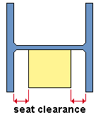
Extend seat to column flange if clearance is less than: The distance between the joist seat and the flange of the column at which connection design is instructed to extend that joist seat to the column flanges.
Angle seat to supporting member : Bolted or Welded . This applies when ' Unstiffened L ' or ' Stiffened L ' is selected as the " Top chord seated material " and ' Automatic ' is selected for " Seat to supporting member " under the seated " ![]() Connection specifications " on the Joist Edit window or at Home > Project Settings > Job > Auto Standard Connections or User Defined Connections .
Connection specifications " on the Joist Edit window or at Home > Project Settings > Job > Auto Standard Connections or User Defined Connections .
Bolted instructs connection design to field bolt the angle seat to the supporting column. The angle shop bolts to the supporting column and the seat field bolts to the joist. The seat is drawn on the column detail.
Welded instructs connection design to shop weld the angle seat to the column. The seat is drawn on the column detail.
Square cut seat stiffener : ![]() or
or ![]() .
.
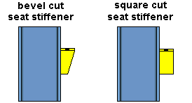
If this box is checked (
), connection design cuts the stiffener plate square to the edge of the seat plate.
If the box is not checked (
), connection design bevel cuts the stiffener.
Bearing connections
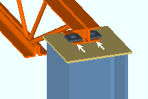
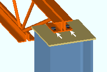
OSHA span for bolted connections: The minimum joist span at which connection design will attempt to bolt the joist's top or bottom chord to the beam's top flange. A joist's span is its " WP to WP length: actual " distance. OSHA stands for Occupational Safety and Health Administration and is the US government regulatory agency responsible for protecting worker health and safety in the United States.
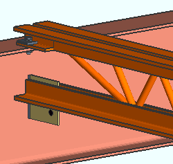
|
An example of a joist that is field bolted to the top flange of a beam. OSHA requires that joists with spans of 40 feet or greater be field bolted during erection. |
If the joist frames to the top of a beam's flange and its " Input connection type " is set to ' Bearing ' and " Chord to support " is set to ' Welded ' and the " OSHA span for bolted connections " is less than the joist's "' WP to WP length: actual ," connection design will attempt to generate a bolted connection even though " Chord to support " was set to ' Welded '. This is also true for similar conditions when the " Input connection type " is ' Auto standard ' or ' User defined '.
Bearing and seated connections
Erection hole diameter : The diameter of the erection hole in a joist's bottom stabilizer plate.
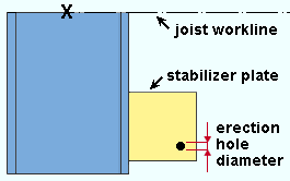
|
Per an OSHA standard, the bottom chord stability plate includes a hole for guying or plumbing cables. That hole is the " Erection hole diameter ." The hole is placed 1 1/2 inch ( from the bottom edge and joist edge of the plate). |
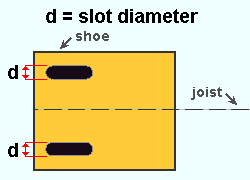
Bearing shoe slot length : The length of the slotted holes in the joist shoe. This applies to slots in joists with either bearing or seated connections.
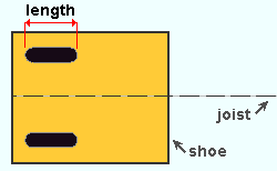
Bearing shoe slot edge distance : The distance from the framing edge of the shoe to the edge of the slot. This dimension is measured parallel with the joist.
Allow washers on bearing shoe slots: ![]() or
or ![]() .
.
When " Allow washers on shoe slots " is ' Automatic ' . . .
If this box is checked (
If the box is not checked (
Flush framed connections
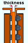
Knife plate thickness: The thickness of the knife plate.
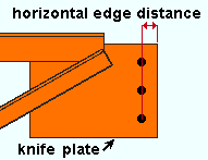
Knife plate horizontal edge distance: The distance from the framing edge of the joist's knife plate to the center of the nearest column of bolts.
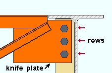
Knife plate minimum bolt row: The minimum number of bolt rows that connection design creates for the attaching of the shear plate or clip angle to the knife plate.
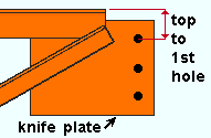
Knife plate top of steel to first row: The distance from the top of the joist to the center of the top hole in the joist's knife plate.
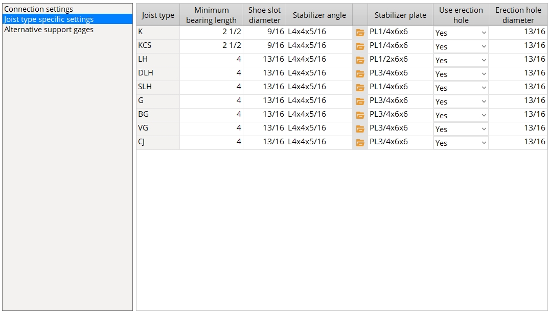
Joist type specific settings
Columns on the "User pre-configured panel" table :
Joist type: Each row in this table has a joist type assigned to it. These joist types include K , KCS , LH and others. Entries to columns in a particular row apply to that joist type. The information that the user enters for a particular " Joist type " may be used for bearing connections and seated connections.
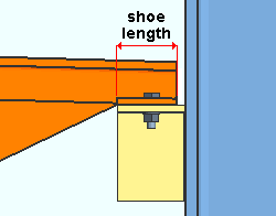
Minimum bearing length : The distance measured parallel with the joist from the outer edge of the shoe to the interior edge of the shoe. The " Shoe length " that connection design enters for "
Shoe slot diameter : The diameter of the slots to be used in the shoes for the " Joist type ".
Note : This only sets the diameter of the slots in the shoe. It does not set the diameter of the holes in the beam flange or seat that the joist shoe bears upon. That diameter is set under " Default bolt criteria " in Bolt Settings .
Stabilizer angle: The section size of the angle to be used when ' Angle ' is selected as the " Stabilizing material " for a bottom chord extension.
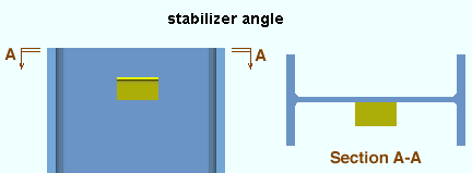
To enter an angle, either type in the section size that you want, or press the "file cabinet" browse button (
) and choose an angle section from the list that appears.
Stabilizer plate: The size of plate to be used when ' Plate ' is selected as the " Stabilizing material " for a bottom chord extension.
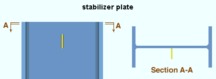
Note :The bottom edge of the plate is placed 3 inches (76 mm) below the joist chord, in accordance with the OSHA standard.
Use erection hole: Yes or No . This applies when the option " Use erection hole " on the Joist Edit window in
" is set to ' Automatic '.Connection specifications "
Yes instructs connection design to add a bottom chord stabilizer plate erection hole when "Use erection hole" is set to 'Automatic'. The bottom chord hole has a 1 1/2 inch edge distance.
No instructs connection design to add a bottom chord stabilizer plate erection hole when "Use erection hole" is set to 'Automatic'.
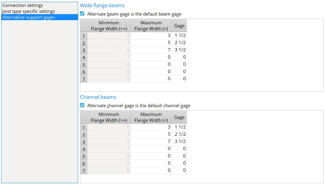
Wide flange beams, alternative suport gages
Alternate beam gage is the default beam gage: ![]() or
or ![]() . This applies when a joist top chord bolts to a wide flange beam's top flange. The joist's "Input elevation" must be the elevation at which the joist bears on the beam's top flange. The joist's "Input connection type" should be 'Bearing' and the "Chord to support" should be set to 'Bolted' for the appropriate end on the Joist Edit window.
. This applies when a joist top chord bolts to a wide flange beam's top flange. The joist's "Input elevation" must be the elevation at which the joist bears on the beam's top flange. The joist's "Input connection type" should be 'Bearing' and the "Chord to support" should be set to 'Bolted' for the appropriate end on the Joist Edit window.
If this box is checked (
If the box is not checked (
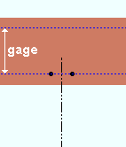
A joist bolted to the top chord of a wide flange beam. The beam's flange gage, which is specified in the local shape file, positions the holes in the flange of the beam.
Channel beams, alternative suport gages
Alternate channel gage is the default channel gage: ![]() or
or ![]() . This applies when a joist top chord bolts to a channel beam's top flange. The joist's "Input elevation" must be the elevation at which the joist bears on the beam's top flange. The joist's "Input connection type" should be 'Bearing' and the "Chord to support" should be set to 'Bolted' for the appropriate end on the Joist Edit window.
. This applies when a joist top chord bolts to a channel beam's top flange. The joist's "Input elevation" must be the elevation at which the joist bears on the beam's top flange. The joist's "Input connection type" should be 'Bearing' and the "Chord to support" should be set to 'Bolted' for the appropriate end on the Joist Edit window.
If this box is checked (
If the box is not checked (
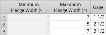
" Section size " that is used by the channel beam that the joist connects to.
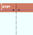
A joist bolted to the top chord of a channel beam. The beam's flange gage, which is specified in the local shape file, positions the holes in the flange of the beam.


|
|
OK (or the Enter key) closes this screen and applies the settings.
Cancel (or the Esc key) closes this screen without saving any changes.
Reset undoes all changes made to this screen since you first opened it. The screen remains open.
- Joist Edit window (settings for specifying joists)
- Connection guide (examples of joist connections)