Member Styles
- Examples (
 )
)
- Three solid member styles (
 )
)
- Tools for changing member styles
- Reasons to display members in solid form
- Reasons members are displayed in stick form
Also see :
| YouTube video: Stick form and the three solid forms are the four different member styles that are available in Modeling . (Recorded in SDS2 Detailing , v2020i) |
- Member worklines (member display in stick form)
- Process and Create Solids (required for display in solid form)
page 1 | contents | topics | view > | view -- solids mode
|

|
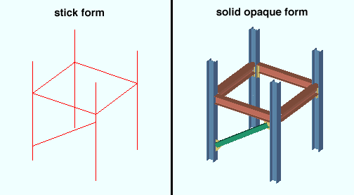
| The same model with members shown in stick form (left) and solid opaque form (right). Two other forms are also available for solid display. |
page 1 | contents | topics | view > | view -- solids mode | top
|
|
|
||
|
solid opaque
|
solid transparent
|
solid transparent main |
Solid opaque = opaque main material & connection material.
Solid transparent = transparent main material & connection material.
Solid transparent main = transparent main material, opaque connection material.
page 1 | contents | topics | view > | view -- solids mode | top
Tools for changing member styles :
The following tools can be used to change the form of members in the 3D model:
- Toggle Stick/Solid
- Change All to Stick
- Change All to Solid Opaque
- Change All to Solid Transparent
- Change All to Solid Transparent Main
- Stick
- Solid Opaque
- Solid Transparent
- Solid Transparent Main
Note: Once you have changed the form of a member, that member will remain in that form even if you change views.
page 1 | contents | topics | view > | view -- solids mode | top
Reasons to display members in solid form :
page 1 | contents | topics | view > | view -- solids mode | top
Reasons members are displayed in stick form :
page 1 | contents | topics | view > | view -- solids mode | top