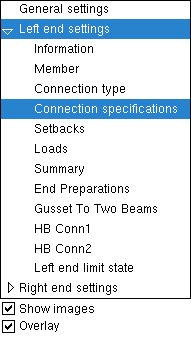
The Horizontal Brace Review window ( Modeling )

  • Settings on the Horizontal Brace Review window are read-only .
  • The " Status " and " Properties " buttons open other windows that are editable.
  • " Change all " options let you apply one member's status changes to all members with the same mark.
  • " Print " or " Expanded Calc " buttons can give you design calculations.
  • Multi-member review: mixed entries are gray.
  • To open this window .

The navigation tree is contained in the left pane of the Horizontal Brace Review window. It makes navigating the window easier.

Selecting a section name shows that section on the Horizontal Brace Review window. In the example at left, " Connection specifications " is selected and, as a result, the " Connection specifications " leaf is expanded (as opposed to collapsed) ( VIDEO1 ). Sections are scrolled to when opened or, if they are already opened, when double-clicked ( VIDEO2 ).

To resize the pane containing the navigation tree, drag its right edge.

" Show images " (when checked) displayes drawings that depict the dimensions that are controlled by connection design locks . ( VIDEO3 )

" Overlay " (when checked) displays one section at a time, just like selecting a tab on a window with tabs displays only the section for that one tab.


General settings
  Left end settings
  Right end settings


  General settings ---------------------------------------------------------------
  Section size   Long leg   Main material
  Piecemark   Double material   Marked for processing
  Piecemark group   One gage line   Marked for detailing
  Steel grade   Stagger bolts   Node-match job
  Surface Finish   Side of gusset   Model complete
  Sequence   Long side   Complete date
  Swap member ends   Allow workline offset  
  Break apart   Min gusset thickness   WP to WP length: plan
    Locate on neutral axis   WP to WP length: actual
    Stitch plate gap  
    Stitch pl spacing
    Number of plates
ABM options apply to a hroizontal brace's " Section size " -- the brace's main material.

Left end settings
Right end settings

General settings
    Left/Right end settings
        Information


Connection Changed Message Connection Failure Message
  Connection :   Connection :
 
context-sensitive help

General settings
    Left/Right end settings
        Member


  Member  -------------------------------------------------------------------------------
  End elevation   Standard detail   
 

General settings
    Left/Right end settings
        Information
        Member
        Connection type


  Connection type  ------------------------------------------------------------------
  Input connection type   NM bolt diameter
  User defined connection   Use miscellaneous plates list
  System designed connection   Minimum setup connection
  NM bolt type   Disable framing situation checks

General settings
    Left/Right end settings
        Information
        Member
        Connection type
        Connection specification


  Connection specifications --------------------------------------------------
  Gusset plate grade   Gusset to clip connection
  Gusset cut   Gusset clips on
  Use OS gusset holes   Clip angle size
  Pipe/tube end fitting   Attach long leg to
  Angle end fitting   Hole type supported
  Include end welds   Hole type supporting
  Balanced welds   Bolt type
  Clip end operation   Bolt diameter
  Gusset to beam connection   Stagger bolts
    Supporting web stress

General settings
    Left/Right end settings
        Member
        Connection type
        Connection specifications
        Setbacks

  Setbacks   -------------------------------------------------------------------------------
  Field clearance   Automatic Minus dimension
  Input minus dimension
 

General settings
    Left/Right end settings
        Member
        Connection type
        Connection specifications
        Setbacks
        Loads

  Loads ------------------------------------------------------------------------------------
  Tension load   Compression load
 

General settings
    Left/Right end settings
        Member
        Connection type
        Connection specifications
        Setbacks
        Loads
        End preparations

  End preparations -----------------------------------------------------------------------
  End-cut type   Moment connection web setback
  Web cut angle   Top flange operation
  Flange cut angle   Bottom flange operation
 

General settings
    Left/Right end settings
        Information
        Member
        Connection type
        Connection specifications
        Setbacks
        Loads
       End preparations
        Connection design locks
        ( brace to top flange )

Tip: Connection design locks may also be found on an edit window for a connection component .


Horizontal Brace to a Beam's Top Flange
    Gusset One Member Square ( angle )
    Brace Connection To Gusset ( angle )
    HB Conn2 ( angle, gusset welded to beam's web )
    Brace Connection To Gusset Hss Bolted ( HSS, pipe, tube )
    Brace Connection To Gusset Hss Paddle ( HSS, pipe, tube )
    Gusset One Member ( HSS, pipe, tube )
    HB Conn2 ( HSS, pipe, tube )
    Gusset One Member Square ( W, WT, 2L )
    Gusset One Member ( L, W, WT, 2L )
    Brace Connection To Gusset ( W, WT, 2L )
    HB Conn2 ( W, WT, 2L )

General settings
    Left/Right end settings
        Information
        Member
        Connection type
        Connection specifications
        Setbacks
        Loads
       End preparations
        Connection design locks
        ( brace to beam web )

Horizontal Brace to a Beam's Web
    Gusset One Member Square ( angle )
    Brace Connection To Gusset ( angle )
    HB Conn 2 ( angle, gusset weld to beam web )
    NS/FS Clip Conn2 ( gusset clip angle(s) to beam web )
    Gusset One Member ( HSS, pipe, tube )
    Brace Connection To Gusset Hss Bolted ( HSS, pipe, tube )
    Brace Connection To Gusset Hss Paddle ( HSS, pipe, tube )
    HB Conn2 ( HSS, pipe, tube, gusset welded to beam's web )
    Gusset One Member Square ( W or WT or 2L to beam web )
    Gusset One Member ( L, W, WT, 2L )
    Brace Connection To Gusset ( W or WT or 2L to beam web )
    HB Conn2 ( W or WT or 2L, gusset weld to beam web )
    Bottom Gusset One Member ( wflg brace to bottom flange )

General settings
    Left/Right end settings
        Information
        Member
        Connection type
        Connection specifications
        Setbacks
        Loads
       End preparations
        Connection design locks
( brace perpendicular to beam )

Horizontal Brace perpendicular to a Beam
    Gusset One Member Perp ( angle, to beam flange )
    Brace Connection To Gusset ( angle, to beam flange )
    HB Conn2 ( angle, gusset weld to beam flange )
    Gusset One Member Perp ( HSS, pipe or tube, to beam web or flange )
    Brace Connection To Gusset Hss Bolted ( HSS, pipe or tube, to web or flange )
    Brace Connection To Gusset Hss Paddle ( HSS, pipe or tube )
    HB Conn2 ( HSS, pipe or tube, gusset weld to beam web or flange )
    NS/FS Clip Conn2 ( gusset clip angle(s) bolted to beam web )
    Gusset One Member Perp ( W or WT brace, perpendicular, to web or flange )
    Brace Connection To Gusset ( W or WT brace, perpendicular, to web or flange )
    HB Conn2 ( W or WT, gusset weld to web or flange )
    Bottom Gusset One Member Perp ( W or WT brace, perp, to bottom flange )
    Gusset One Member Perp ( angle, to beam web )
    HB Connection To Gusset ( angle, to beam web )
    HB Conn2 ( angle, gusset weld to beam web )

General settings
    Left/Right end settings
        Information
        Member
        Connection type
        Connection specifications
        Setbacks
        Loads
       End preparations
        Connection design locks
     ( 2 point bracing )


Note:
2-point bracing is shown, but the pages these links go to also apply to 3-point bracing.

Horizontal Brace Shared 'k' Connection (2- or 3-point bracing)
    Gusset 2 Point Square ( angle braces, to top flange )
    Brace Connection To Gusset ( angle braces, to top flange )
    HB Conn2 ( angle braces, gusset weld to top flange )
    Gusset 2 Point ( HSS, pipe or tube braces, to top flange )
    Brace Connection To Gusset Hss Bolted ( HSS, pipe or tube, web or flange )
    Brace Connection To Gusset Hss Paddle ( HSS, pipe or tube )
    HB Conn2 ( HSS, pipe or tube braces, gusset weld to top flange )
    Gusset 2 Point Square ( W, 2L or WT braces, shared gusset, to top flange )
    Gusset 2 Point ( L, W, 2L or WT braces, shared gusset, to flange or web )
    Brace Connection To Member ( W, 2L or WT braces, to top flange )
    HB Conn2 ( W, 2L or WT braces, gusset weld to top flange )
    Gusset 2 Point ( angle braces, to beam web )
    Brace Connection To Gusset ( angle braces, to beam web )
    HB Conn2 ( angle braces, gusset weld to beam web )
    NS/FS Clip Conn2 ( clip angle(s) bolted to beam web )
    Gusset 2 Point ( HSS, pipe or tube braces, to beam web )
    HB Conn2 ( HSS, pipe or tube braces, gusset weld to beam web )
    Gusset 2 Point ( W, 2L or WT braces, to beam web )
    Brace Connection To Gusset ( W, 2L or WT braces, to beam web )
    Bottom Gusset 2 Point ( W braces, to beam bottom flange )

General settings
    Left/Right end settings
        Information
        Member
        Connection type
        Connection specifications
        Setbacks
        Loads
       End preparations
        Connection design locks
        ( brace to top flange )

Horizontal Brace Intersection (X bracing)
  Gusset Intersection ( angle braces )
  Brace Connection To Gusset ( angle braces )
  Gusset Intersection ( WT braces )
  Brace Connection To Gusset ( WT braces )
  Gusset Intersection ( HSS, pipe or tube braces )
  Brace Connection To Gusset ( HSS, pipe or tube braces )
  Brace Connection To Gusset Hss Paddle ( HSS, pipe or tube )

General settings
    Left/Right end settings
        Information
        Member
        Connection type
        Connection specifications
        Setbacks
        Loads
       End preparations
        Connection design locks
        ( beam-beam corner )

Horizontal Brace to Beam-Beam Corner
  HB Conn1 or HB Conn2 ( bolted to top flanges )
  Clip Angle or NS/FS Clip Conn2 ( gusset clips, web )
  Gusset To Two Beams Square ( angle brace )
  Brace Connection To Gusset Square ( angle brace )
  Gusset To Two Beams ( HSS, piper or tube brace )
  Brace Connection to Gusset ( HSS, pipe or tube brace )
  Brace Connection to Gusset Hss Paddle ( HSS, pipe or tube brace )
  Gusset To Two Beams Square ( W, 2L or WT brace )
  Gusset To Two Beams ( L, W, 2L, WT )
  Brace Conn To Gusset ( W, 2L or WT brace )

General settings
    Left/Right end settings
        Information
        Member
        Connection type
        Connection specifications
        Setbacks
        Loads
       End preparations
        Connection design locks
( beam-column-beam corner )

Horizontal Brace to Beam-Column-Beam Corner
  HB Conn2 or HB Conn2 ( bolted to top flanges )
  NS/FS Clip Conn1 or NS/FS Clip Conn2 ( gusset clips, web )
  Gusset To Two Beams Square ( angle brace )
  Brace Connection To Gusset Square ( angle brace )
  Gusset To Two Beams ( HSS, pipe or tube brace )
  Brace Connection To Gusset ( HSS, pipe or tube brace )
  Brace Connection To Gusset Hss Paddle ( HSS, pipe or tube brace )
  Gusset To Two Beams Square ( W, 2L or WT brace )
  Gusset To Two Beams ( L, W, 2L, WT )
  Brace Connection To Gusset ( W, 2L or WT brace )

General settings
    Left/Right end settings
        Information
        Member
        Connection type
        Connection specifications
        Setbacks
        Loads
       End preparations
        Connection design locks
       Left/Right end limit state

  Left/Right end limit state ------------------------------------------------------------------------------

--- The capacity of a connection is calculated for various limit states during connection design .

--- Connection design takes place in a full-featured SDS2 program , but not in SDS2 Site Planning.

--- You can review the results of connection design by reviewing connection design locks , by outputting a Connection Design Calculations Report or the Expanded Connection Design Calculations , or by visual inspection of the model.


General settings
    Left/Right end settings
        Information
        Member
        Connection type
        Connection specifications
        Setbacks
        Loads
       End preparations
        Connection design locks
        Left/Right end limit state
        Components

  Components ------------------------------------------------------------------------------------------------

--- Custom component settings will appear on the Horizontal Brace Review window only if a custom component has been added in a full-featured SDS2 program . You cannot add a custom component in SDS2 Site Planning.

--- One custom component whose settings may appear on a Horizontal Brace Review window is " HSS Cap Plates ."


To open the Horizontal Brace Review window :

Also see :

page 1 | contents | model > member | top