Bevel Symbol Edit Window
- General Overview
- Related Tools
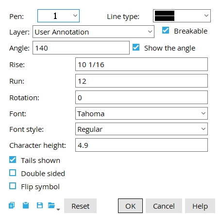
Pen: 1-7. Select the printing pen number (and on-screen display color) of the Bevel Symbol.
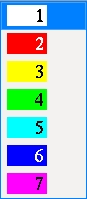
Tip:Line Weights sets the printed thickness for each of the seven pen numbers.
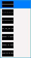
Line type: Select the line type of the ellipse.
Layer: The drawing layer the bevel symbol is drawn on.
Defaults: For an add operation, the default selection made here is the layer that was selected on the
Layer Panel before you began the operation. For an edit operation, the default selection is the layer that the bevel symbol is currently on.
Breakable: ![]() or
or ![]() . This applies when the option
. This applies when the option ![]() Break bevel lines at label interference is checked. If that setup option is not checked, then the bevel lines are never broken.
Break bevel lines at label interference is checked. If that setup option is not checked, then the bevel lines are never broken.
|

If this box
is checked and Home > Project Settings > Fabricator > Detailing > Dimension Settings > the General tab > Break bevel lines at label interference is checked, the bevel line breaks where it crosses a label.
If the box
is not checked, the line is continuous through any labels or dimension labels it crosses.
Angle: The positive or negative (-) number of degrees that defines the angle through the two exact points of the bevel symbol .
Note: Changing the Angle updates the Riseand Run of the bevel symbol.
A positive number moves the second point counterclockwise to the number of degrees from the imaginary horizontal line drawn through the first point.
A negative number positions the exact point on the triangle clockwise that number of degrees from the imaginary horizontal line drawn through the tail.
If the box
If the box
Rise: may be entered to the rise position on the bevel symbol.

Run: may be entered here to appear in the run position of the bevel symbol .
Rotation: A positive or negative number of degrees. Rotation is around the tip of the bevel symbol's tail.

Font: Any font that is listed can be selected for the Rise and Run characters in the bevel symbol.
Font style: The style of the selected bevel symbol Font. Different fonts may have different styles available to them.
If this box
If the box
If this box
If the box
|
If this box
If the box


|
|
OK (or the Enter key) closes this screen and applies the settings.
Cancel (or the Esc key) closes this screen without saving any changes.
Reset undoes all changes made to this screen since you first opened it. The screen remains open.

